Cisco 2970G-24T - Catalyst Switch Support and Manuals
Get Help and Manuals for this Cisco item
View All Support Options Below
Free Cisco 2970G-24T manuals!
Problems with Cisco 2970G-24T?
Ask a Question
Free Cisco 2970G-24T manuals!
Problems with Cisco 2970G-24T?
Ask a Question
Popular Cisco 2970G-24T Manual Pages
Hardware Installation Guide - Page 6
...21 Internal Power Supply Connector 1-21 DC Power Connector 1-21 Cisco RPS Connector 1-22
Console Port 1-23
2 C H A P T E R
Installation 2-1
Preparing for Installation 2-1 Warnings 2-1 EMC Regulatory Statements 2-4 U.S.A. 2-4 Taiwan 2-4 Japan 2-5 Korea 2-5 Hungary 2-6 Installation Guidelines 2-6 Verifying Package Contents 2-7
Installing the Switch on a Table or Shelf 2-9
Installing the Switch in...
Hardware Installation Guide - Page 26
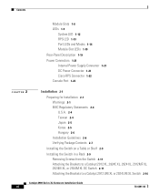
... up to the Catalyst 2900 Series XL and Catalyst 3500 Series XL Software Configuration Guide for Cisco IP Phones and per-port priority override.
Unlike the 3524-PWR XL switch, the Catalyst 2900 XL switches do not provide inline power. Catalyst 2900 Series XL Hardware Installation Guide
1-6
78-6461-04 Pinouts for autonegotiation, the port senses the speed and duplex settings of half duplex...
Hardware Installation Guide - Page 33
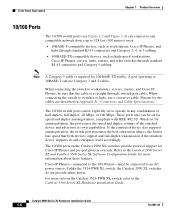
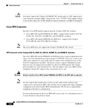
... (model PWR600-AC-RPS). All other Catalyst 2900 XL and Catalyst 3500 XL switches use the Cisco RPS 300 (model PWR300-AC-RPS-N1). Refer to provide back-up . Note This is connected and ready to the appropriate switch documentation for redundant power system (RPS) descriptions specific for the switch. RPS is connected but is unavailable because it is not installed.
Hardware Installation Guide - Page 34

... ports: auto The port operating speed: 10 or 100 Mbps.
1-14
Catalyst 2900 Series XL Hardware Installation Guide
78-6461-04 Table 1-6 and Table 1-7 list the port LED colors. Table 1-4 Port Mode LEDs on the RPS, and the LED should turn green.
If it does not, the RPS fan could have a port LED. This is providing power to the switch...
Hardware Installation Guide - Page 38
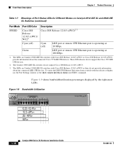
... 12.5 -24%+ 25 - 49%+ 50%+
Catalyst 2900 SERIES XL
1-18
Catalyst 2900 Series XL Hardware Installation Guide
78-6461-04
These IOS releases do not support Cisco IOS Release 12.0(5.x)WC3.
3.
Front-Panel Description
Chapter 1 Product Overview
Table 1-7 Meanings of Port Status LEDs for Different Modes on Catalyst 2912 LRE XL and 2924 LRE XL Switches (continued)
Port Mode SPEED
Port LED...
Hardware Installation Guide - Page 39
...).
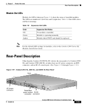
Note For the default LED settings for modules, refer to the Catalyst 2900 Series XL Modules Installation Guide.
Table 1-8 Expansion Slot LEDs
Color Off Green Amber
Expansion Slot Status No module is operating normally. Module is installed. Rear-Panel Description
Other than the Catalyst 2924M XL DC switch, the rear panels of installed modules. Table 1-8 lists LED colors...
Hardware Installation Guide - Page 40
...
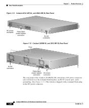
Redundant power system AC power
connector connector
The rear panel of the Catalyst 2924M XL DC switch has a DC power connector (also referred to as the terminal block header), an RJ-45 console port, and a ground lug. (See Figure 1-13.) The switch is shipped with a terminal block plug in the DC power connector.
1-20
Catalyst 2900 Series XL Hardware Installation Guide...
Hardware Installation Guide - Page 41
Internal Power Supply Connector
The internal power supply is an autoranging unit that are diode-OR-ed into a single power block. For installation instructions, see the "Wiring the DC-Input Power Source" section on page 2-29.
78-6461-04
Catalyst 2900 Series XL Hardware Installation Guide
1-21 Chapter 1 Product Overview
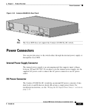
Figure 1-13 Catalyst 2924M XL Rear Panel
Power Connectors
74070
CONSOLE...
Hardware Installation Guide - Page 42
... that has an input supply voltage from -36 to the Cisco Redundant Power System Hardware Installation Guide.
1-22
Catalyst 2900 Series XL Hardware Installation Guide
78-6461-04 Power Connectors
Chapter 1 Product Overview
Caution
You must connect the Catalyst 2924M XL DC switch only to a DC-input power source that use up to 150W DC each. We do not support the fully-redundant...
Hardware Installation Guide - Page 43
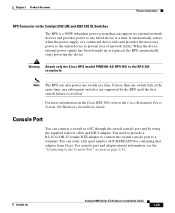
... using the supplied rollover cable and DB-9 adapter.
Console Port
You can order a kit (part number ACS-DSBUASYN=) containing that can support six external network devices and provides power to one switch fails at a time. Chapter 1 Product Overview
Power Connectors
RPS Connector on the Cisco RPS 300, refer to the Cisco Redundant Power System 300 Hardware Installation Guide. You need...
Hardware Installation Guide - Page 50
... verify that does not have an on/off switch. Catalyst 2900 Series XL Hardware Installation Guide
2-6
78-6461-04 Preparing for Installation
Chapter 2 Installation
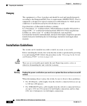
Hungary
This equipment is a Class A product and should be used . Class A equipment is operational by powering it on a wall. Follow the procedures in a rack, or on and running POST.
When determining where to...
Hardware Installation Guide - Page 53
... on page 2-24.
Note Figure 2-1 shows brackets for one-rack-unit switches.
78-6461-04
Catalyst 2900 Series XL Hardware Installation Guide
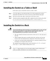
2-9 The supplied rack-mounting brackets can be mounted at the bottom of the rack.
• If the rack is mounted on the table or shelf, power the switch as described in "Powering On the Switch and Running POST...
Hardware Installation Guide - Page 63
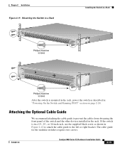
... the left or right bracket. If the switch is mounted in the rack, power the switch as shown in the rack. The cable guide for the modular switches requires two screws.
78-6461-04
Catalyst 2900 Series XL Hardware Installation Guide
2-19 Chapter 2 Installation
Figure 2-11 Mounting the Switch in a Rack
Installing the Switch in a Rack
MODE
1X
2X
3X
4X
5X...
Hardware Installation Guide - Page 68
..." section on page 2-24.
Catalyst 2900 Series XL Hardware Installation Guide
78-6461-04 SERIES
16x
17x
18x
19x
20x
21x
22x
23x
24x
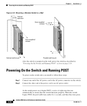
Powering On the Switch and Running POST
Figure 2-16 Mounting a Modular Switch to the AC power connector on the switch. Step 2 Connect the other end of the power cord to an AC power outlet.
2-24
As the switch powers on, it...
Hardware Installation Guide - Page 159
... 1-16 to 1-18 LRE 1-7 module 1-8 port status LEDs 1-9, 1-16 to 1-18
port status LEDs 1-9, 1-16 to 1-18 POST results 2-24 power
connecting to 2-24 warning C-15 power connectors 1-21 power on 2-24 power supply AC power outlet 1-21 RPS connector 1-21 warning C-17 product disposal warning C-21
Q
qualified personnel warning C-3
78-6461-04
Catalyst 2900 Series XL Hardware Installation Guide
IN-5
Cisco 2970G-24T Reviews
We have not received any reviews for Cisco yet.