
Installation Guide
Page 6
... Description 1-21 Power Connectors 1-22 Internal Power Supply Connector 1-23 Cisco RPS Connector 1-23 Console Port 1-24 Management Options 1-24 Network Configuration Examples 1-25 Design Concepts for Installation 2-2 Warnings 2-2 EMC Regulatory Statements 2-5 U.S.A. 2-5 Taiwan 2-5 Japan 2-6 Korea 2-6 Hungary 2-7 Installation Guidelines 2-7 Verifying Package Contents 2-8 Catalyst 3500 Series XL Hardware Installation Guide vi 78-6456-03 to Medium-Sized...
... Description 1-21 Power Connectors 1-22 Internal Power Supply Connector 1-23 Cisco RPS Connector 1-23 Console Port 1-24 Management Options 1-24 Network Configuration Examples 1-25 Design Concepts for Installation 2-2 Warnings 2-2 EMC Regulatory Statements 2-5 U.S.A. 2-5 Taiwan 2-5 Japan 2-6 Korea 2-6 Hungary 2-7 Installation Guidelines 2-7 Verifying Package Contents 2-8 Catalyst 3500 Series XL Hardware Installation Guide vi 78-6456-03 to Medium-Sized...
Installation Guide
Page 7
...Switch on a Wall 2-15 Attaching the Brackets to the Switch 2-15 Attaching the Switch to a Wall 2-16 Installing the Switch on a Table or Shelf 2-17 Powering On the Switch... and Running POST 2-17 Connecting to the 10/100 Ports 2-18 Connecting to the GBIC Module Ports 2-20 Connecting to a 1000BaseX GBIC Module Port 2-21 Connecting to a GigaStack GBIC Module Port 2-22 Connecting a PC or Terminal to the Console Port 2-23 Assigning Switch... Information 2-24 Using the Setup Program 2-25 Using BOOTP ...
...Switch on a Wall 2-15 Attaching the Brackets to the Switch 2-15 Attaching the Switch to a Wall 2-16 Installing the Switch on a Table or Shelf 2-17 Powering On the Switch... and Running POST 2-17 Connecting to the 10/100 Ports 2-18 Connecting to the GBIC Module Ports 2-20 Connecting to a 1000BaseX GBIC Module Port 2-21 Connecting to a GigaStack GBIC Module Port 2-22 Connecting a PC or Terminal to the Console Port 2-23 Assigning Switch... Information 2-24 Using the Setup Program 2-25 Using BOOTP ...

Installation Guide
Page 9
INDEX Grounded Equipment Warning C-23 Supply Circuit Warning C-24 No On/Off Switch Warning C-25 Power Supply Warning C-27 Work During Lightning Activity Warning C-30 Product Disposal Warning C-31 Chassis Warning-Rack-Mounting and Servicing C-33 Chassis Power Connection Warning C-38 Shock Hazard from Interconnections Warning C-41 Contents 78-6456-03 Catalyst 3500 Series XL Hardware Installation Guide ix
INDEX Grounded Equipment Warning C-23 Supply Circuit Warning C-24 No On/Off Switch Warning C-25 Power Supply Warning C-27 Work During Lightning Activity Warning C-30 Product Disposal Warning C-31 Chassis Warning-Rack-Mounting and Servicing C-33 Chassis Power Connection Warning C-38 Shock Hazard from Interconnections Warning C-41 Contents 78-6456-03 Catalyst 3500 Series XL Hardware Installation Guide ix
Installation Guide
Page 20
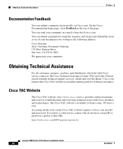
... the front cover of the page. The Cisco TAC website is available 24 hours a day, 365 days a year. Accessing all customers, partners, resellers, and distributors who hold valid Cisco service contracts, the Cisco Technical Assistance Center (TAC) provides 24-hour, award-winning technical support services, online...at the top of your comments. You can submit comments by writing to bug-doc@cisco.com. On the Cisco Documentation home page, click Feedback at this URL: http://tools.cisco.com/RPF/register/register.do Catalyst 3500 Series XL Hardware Installation Guide xx 78-6456-04
... the front cover of the page. The Cisco TAC website is available 24 hours a day, 365 days a year. Accessing all customers, partners, resellers, and distributors who hold valid Cisco service contracts, the Cisco Technical Assistance Center (TAC) provides 24-hour, award-winning technical support services, online...at the top of your comments. You can submit comments by writing to bug-doc@cisco.com. On the Cisco Documentation home page, click Feedback at this URL: http://tools.cisco.com/RPF/register/register.do Catalyst 3500 Series XL Hardware Installation Guide xx 78-6456-04
Installation Guide
Page 26
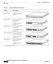
... 1 Product Overview Figure 1-1 Catalyst 3500 Series XL Switches Switch Description WS-C3508G-XL 8 GBIC1-based gigabit module slots 1 SYSTEM 2 3 RPS 4 5 MODE STATUS UTIL DUPLX SPEED 6 7 8 WS-C3512-XL 12 autosensing10/100 Ethernet ports 2 GBIC-based gigabit module slots WS-C3524-XL 24 autosensing 10/100 Ethernet ports 2 fixed GBIC-based gigabit module slots WS-C3524-PWR-XL 24 autosensing 10/100...
... 1 Product Overview Figure 1-1 Catalyst 3500 Series XL Switches Switch Description WS-C3508G-XL 8 GBIC1-based gigabit module slots 1 SYSTEM 2 3 RPS 4 5 MODE STATUS UTIL DUPLX SPEED 6 7 8 WS-C3512-XL 12 autosensing10/100 Ethernet ports 2 GBIC-based gigabit module slots WS-C3524-XL 24 autosensing 10/100 Ethernet ports 2 fixed GBIC-based gigabit module slots WS-C3524-PWR-XL 24 autosensing 10/100...
Installation Guide
Page 28
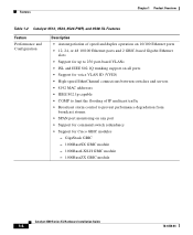
Features Chapter 1 Product Overview Table 1-2 Catalyst 3512, 3524, 3524-PWR, and 3548 XL Features Feature Performance and Configuration Description • Autonegotiation of speed and duplex operation on 10/100 Ethernet ports • 12, 24, or 48 10/100 Ethernet ports and 2 GBIC-based Gigabit Ethernet...• SPAN port monitoring on any port • Support for command switch redundancy • Support for Cisco GBIC modules - GigaStack GBIC - 1000BaseSX GBIC module - 1000BaseLX/LH GBIC module - 1000BaseZX GBIC module Catalyst 3500 Series XL Hardware Installation Guide 1-4 78-6456-04
Features Chapter 1 Product Overview Table 1-2 Catalyst 3512, 3524, 3524-PWR, and 3548 XL Features Feature Performance and Configuration Description • Autonegotiation of speed and duplex operation on 10/100 Ethernet ports • 12, 24, or 48 10/100 Ethernet ports and 2 GBIC-based Gigabit Ethernet...• SPAN port monitoring on any port • Support for command switch redundancy • Support for Cisco GBIC modules - GigaStack GBIC - 1000BaseSX GBIC module - 1000BaseLX/LH GBIC module - 1000BaseZX GBIC module Catalyst 3500 Series XL Hardware Installation Guide 1-4 78-6456-04

Installation Guide
Page 29
... AC input and supplies DC output to the Catalyst 3512, 3524, and 3548 XL switches • Connection for optional Cisco RPS 300 that operates on AC input and supplies DC output to the Catalyst 3524-PWR XL switch Inline Power (Catalyst 3524-PWR XL switch only) • Ability to provide inline power for Cisco IP Phones from all 24 10/100 Ethernet ports • Auto-detection and...
... AC input and supplies DC output to the Catalyst 3512, 3524, and 3548 XL switches • Connection for optional Cisco RPS 300 that operates on AC input and supplies DC output to the Catalyst 3524-PWR XL switch Inline Power (Catalyst 3524-PWR XL switch only) • Ability to provide inline power for Cisco IP Phones from all 24 10/100 Ethernet ports • Auto-detection and...

Installation Guide
Page 30
... 1X 34 56 78 SYSTEM MODE RPS 2X STATUS UTIL DUPLX SPEED 9 10 11 12 11X 12X 10/100 ports Figure 1-4 Catalyst 3524 XL Switch 1 2 GBIC module slots 12 1X 34 56 78 MODE SYSTEM RPS STATUS 2X UTIL DUPLX SPEED 9 10 11 12 11X 12X 13 14 13X 15 ...16 17 18 19 20 21 22 23 24 23X 14X 24X 10/100 ports 1 2 GBIC module slots Catalyst 3500 Series XL Hardware Installation Guide 1-6 26237 26235 78-6456-04
... 1X 34 56 78 SYSTEM MODE RPS 2X STATUS UTIL DUPLX SPEED 9 10 11 12 11X 12X 10/100 ports Figure 1-4 Catalyst 3524 XL Switch 1 2 GBIC module slots 12 1X 34 56 78 MODE SYSTEM RPS STATUS 2X UTIL DUPLX SPEED 9 10 11 12 11X 12X 13 14 13X 15 ...16 17 18 19 20 21 22 23 24 23X 14X 24X 10/100 ports 1 2 GBIC module slots Catalyst 3500 Series XL Hardware Installation Guide 1-6 26237 26235 78-6456-04

Installation Guide
Page 31
...10BaseT-compatible devices such as workstations, Cisco IP Phones, and hubs through standard RJ-45 connectors and Category 3, 4, or 5 cabling 78-6456-04 Catalyst 3500 Series XL Hardware Installation Guide 1-7 Chapter 1 Product Overview Figure 1-5 Catalyst 3524-PWR XL Switch Front-Panel Description 30291 12 1X ...34 56 78 MODE SYSTEM RPS STATUS 2X DUPLX SPEED LINE PWR 9 10 11 12 11X 12X 13 14 13X 15 16 17 18 19 20 21 22 23 24 23X 14X 24X 10/100 inline-power ports Figure 1-6 Catalyst 3548 XL Switch...
...10BaseT-compatible devices such as workstations, Cisco IP Phones, and hubs through standard RJ-45 connectors and Category 3, 4, or 5 cabling 78-6456-04 Catalyst 3500 Series XL Hardware Installation Guide 1-7 Chapter 1 Product Overview Figure 1-5 Catalyst 3524-PWR XL Switch Front-Panel Description 30291 12 1X ...34 56 78 MODE SYSTEM RPS STATUS 2X DUPLX SPEED LINE PWR 9 10 11 12 11X 12X 13 14 13X 15 16 17 18 19 20 21 22 23 24 23X 14X 24X 10/100 inline-power ports Figure 1-6 Catalyst 3548 XL Switch...

Installation Guide
Page 44
...STATUS UTIL DUPLX SPEED 12 1X 34 56 78 9 10 11 12 11X 2X 12X < 25% + 25% - 49% + 50% + Catalyst 3500 XL 1 2 22007 Figure 1-15 Bandwidth Utilization for the Catalyst 3524 XL Switch MODE SYSTEM RPS STATUS UTIL DUPLX SPEED 12 1X 34 56 78 9 10 11 12 11X 2X 12X 13 14 15... 16 13X 17 18 19 20 21 22 23 24 15X 14X 16X < 25% + 25% - 49% + 50% + Catalyst 3500 XL 1 2 Figure 1-16 Bandwidth Utilization for the Catalyst 3548 XL Switch 28366 ...
...STATUS UTIL DUPLX SPEED 12 1X 34 56 78 9 10 11 12 11X 2X 12X < 25% + 25% - 49% + 50% + Catalyst 3500 XL 1 2 22007 Figure 1-15 Bandwidth Utilization for the Catalyst 3524 XL Switch MODE SYSTEM RPS STATUS UTIL DUPLX SPEED 12 1X 34 56 78 9 10 11 12 11X 2X 12X 13 14 15... 16 13X 17 18 19 20 21 22 23 24 15X 14X 16X < 25% + 25% - 49% + 50% + Catalyst 3500 XL 1 2 Figure 1-16 Bandwidth Utilization for the Catalyst 3548 XL Switch 28366 ...
Installation Guide
Page 48
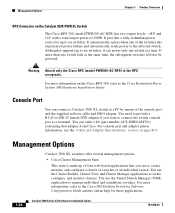
It automatically senses when one of switches or an individual switch. For more information on the Catalyst 3524-PWR XL Switch The Cisco RPS 300 (model PWR300-AC-RPS) has two output levels: -48V and ...24 Catalyst 3500 Series XL Hardware Installation Guide 78-6456-04 Warning Attach only the Cisco RPS (model PWR300-AC-RPS) to manage individual and standalone switches. You can connect a Catalyst 3500 XL switch to a PC by means of four web-based applications that adapter from Cisco. Although it can power only one switch fails at a time. Management Options Catalyst 3500 XL switches...
It automatically senses when one of switches or an individual switch. For more information on the Catalyst 3524-PWR XL Switch The Cisco RPS 300 (model PWR300-AC-RPS) has two output levels: -48V and ...24 Catalyst 3500 Series XL Hardware Installation Guide 78-6456-04 Warning Attach only the Cisco RPS (model PWR300-AC-RPS) to manage individual and standalone switches. You can connect a Catalyst 3500 XL switch to a PC by means of four web-based applications that adapter from Cisco. Although it can power only one switch fails at a time. Management Options Catalyst 3500 XL switches...
Installation Guide
Page 57
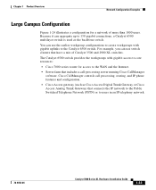
... to create workgroups with gigabit access to core resources: • Cisco 7000 series router for a network of Catalyst 3500 and 2900 XL switches. The Catalyst 6500 switch provides the workgroups with gigabit uplinks to the Catalyst 6500 switch. Chapter 1 Product Overview Network Configuration Examples Large Campus Configuration Figure 1-24 illustrates a configuration for access to the WAN and the Internet...
... to create workgroups with gigabit access to core resources: • Cisco 7000 series router for a network of Catalyst 3500 and 2900 XL switches. The Catalyst 6500 switch provides the workgroups with gigabit uplinks to the Catalyst 6500 switch. Chapter 1 Product Overview Network Configuration Examples Large Campus Configuration Figure 1-24 illustrates a configuration for access to the WAN and the Internet...
Installation Guide
Page 58
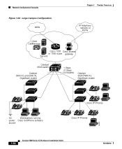
Network Configuration Examples Chapter 1 Product Overview Figure 1-24 Large Campus Configuration WAN IP telephony network or PSTN Cisco CallManager Cisco 7200 Cisco access or 7500 router gateway Servers Catalyst 6500 switch Catalyst 3500 XL and 2900 XL GigaStack cluster 1 Gbps (2 Gbps full duplex) Catalyst 3524-PWR XL GigaStack cluster IP IP AC Workstations running power Cisco SoftPhone software source IP IP Cisco IP Phones IP IP IP Cisco IP Phones 33093 1-34 Catalyst 3500 Series XL Hardware Installation Guide 78-6456-04
Network Configuration Examples Chapter 1 Product Overview Figure 1-24 Large Campus Configuration WAN IP telephony network or PSTN Cisco CallManager Cisco 7200 Cisco access or 7500 router gateway Servers Catalyst 6500 switch Catalyst 3500 XL and 2900 XL GigaStack cluster 1 Gbps (2 Gbps full duplex) Catalyst 3524-PWR XL GigaStack cluster IP IP AC Workstations running power Cisco SoftPhone software source IP IP Cisco IP Phones IP IP IP Cisco IP Phones 33093 1-34 Catalyst 3500 Series XL Hardware Installation Guide 78-6456-04

Installation Guide
Page 67
...78-6456-04 Catalyst 3500 Series XL Hardware Installation Guide 2-9 Four Phillips machine screws for attaching the brackets to the switch - Chapter 2 Installing and Starting Up the Switch Installing the Switch in the rack. Four rubber feet for attaching the brackets to the switch - or 24-inch rack. ...45-to-RJ-45 rollover cable • One RJ-45-to-DB-9 female adapter • Cisco Information Packet, containing warranty, safety, and support information Installing the Switch in a Rack Warning To prevent bodily injury when mounting or servicing this unit in a partially filled...
...78-6456-04 Catalyst 3500 Series XL Hardware Installation Guide 2-9 Four Phillips machine screws for attaching the brackets to the switch - Chapter 2 Installing and Starting Up the Switch Installing the Switch in the rack. Four rubber feet for attaching the brackets to the switch - or 24-inch rack. ...45-to-RJ-45 rollover cable • One RJ-45-to-DB-9 female adapter • Cisco Information Packet, containing warranty, safety, and support information Installing the Switch in a Rack Warning To prevent bodily injury when mounting or servicing this unit in a partially filled...

Installation Guide
Page 68
...Catalyst 3508G XL switch as shown here. Installing the Switch in a Rack Chapter 2 Installing and Starting Up the Switch Note The illustrations in the series (Catalyst 3512, 3524, 3524-PWR, and 3548 XL) can be installed as an example. Follow the same procedure for the opposite side. 2-10 Catalyst 3500 Series XL...rack mount point 24" rack mount point To install the switch in a 19-inch or a 24-inch standard rack, follow the instructions described in these procedures: • Removing screws from the switch • Attaching the brackets to install the Catalyst 3548 XL switch in a ...
...Catalyst 3508G XL switch as shown here. Installing the Switch in a Rack Chapter 2 Installing and Starting Up the Switch Note The illustrations in the series (Catalyst 3512, 3524, 3524-PWR, and 3548 XL) can be installed as an example. Follow the same procedure for the opposite side. 2-10 Catalyst 3500 Series XL...rack mount point 24" rack mount point To install the switch in a 19-inch or a 24-inch standard rack, follow the instructions described in these procedures: • Removing screws from the switch • Attaching the brackets to install the Catalyst 3548 XL switch in a ...

Installation Guide
Page 69
...the long side of the switch. Figure 2-3 Attaching Brackets for a 19-inch or a 24-inch rack. and 24-Inch Racks (Front Panel Forward) Phillips flat-head screws 22437 1 SYSTEM RPS MODE STATUS UTIL DUPLX SPEED 19" Configuration 2 3 78-6456-04 Catalyst 3500 Series XL Hardware Installation Guide 2-11... Follow the same steps to attach the second bracket to one side of the bracket to the switch. • For a 24-inch rack, use depend on whether you use the supplied number...
...the long side of the switch. Figure 2-3 Attaching Brackets for a 19-inch or a 24-inch rack. and 24-Inch Racks (Front Panel Forward) Phillips flat-head screws 22437 1 SYSTEM RPS MODE STATUS UTIL DUPLX SPEED 19" Configuration 2 3 78-6456-04 Catalyst 3500 Series XL Hardware Installation Guide 2-11... Follow the same steps to attach the second bracket to one side of the bracket to the switch. • For a 24-inch rack, use depend on whether you use the supplied number...

Installation Guide
Page 70
... INPUTS SPECIFIED IFNOMRARNEUMAOL.T+E3P.3OVW***E@R1S4UAP, PLY DC INPUT +12V***@3A 24" Configuration Phillips flat-head screws Phillips truss-head screws 22440 2-12 Catalyst 3500 Series XL Hardware Installation Guide 78-6456-04 Installing the Switch in a Rack Chapter 2 Installing and Starting Up the Switch Phillips truss-head screws 1 SYSTEM RPS MODE STATUS UTIL DUPLX...
... INPUTS SPECIFIED IFNOMRARNEUMAOL.T+E3P.3OVW***E@R1S4UAP, PLY DC INPUT +12V***@3A 24" Configuration Phillips flat-head screws Phillips truss-head screws 22440 2-12 Catalyst 3500 Series XL Hardware Installation Guide 78-6456-04 Installing the Switch in a Rack Chapter 2 Installing and Starting Up the Switch Phillips truss-head screws 1 SYSTEM RPS MODE STATUS UTIL DUPLX...

Installation Guide
Page 71
... 2 Installing and Starting Up the Switch Installing the Switch in a Rack Mounting the Switch in a Rack After the brackets are using the Cisco RPS, see the Cisco RPS documentation for 2 seconds, and then it flashes green while the switch completes the series of the switch and the other devices installed in the... to the left or right bracket. 78-6456-04 Catalyst 3500 Series XL Hardware Installation Guide 2-13 If the switch is connected, the System LED turns amber for installation instructions. After the power is in a 19-inch or 24-inch rack, use the four supplied number-12 Phillips...
... 2 Installing and Starting Up the Switch Installing the Switch in a Rack Mounting the Switch in a Rack After the brackets are using the Cisco RPS, see the Cisco RPS documentation for 2 seconds, and then it flashes green while the switch completes the series of the switch and the other devices installed in the... to the left or right bracket. 78-6456-04 Catalyst 3500 Series XL Hardware Installation Guide 2-13 If the switch is connected, the System LED turns amber for installation instructions. After the power is in a 19-inch or 24-inch rack, use the four supplied number-12 Phillips...

Installation Guide
Page 72
Figure 2-6 Attaching the Cable Guide to a 3512, 3524, 3524-PWR, or 3508 XL Switch 1 MODE SYSTEM RPS 2 3 4 5 STATUS UTIL DUPLX SPEED 6 7 8 Cable guide screw Figure 2-7 Attaching the Cable Guide to 48 cables. This cable guide secures up to a 3548 XL Switch SYSTEM RPS 12 1X 34 56 78 9 10 11 12 13 14 15 16 15X 17 18... 21 22 23 24 25 26 27 28 29 30 31 32 31X 33 34 33X 35 36 37 38 39 40 41 42 43 44 45 46 47 48 47X STATUS UTIL 1 DUPLEX SPEED 2X MODE 16X 18X 32X 34X 48X 2 Cable guide screw 28324 2-14 Catalyst 3500 Series XL Hardware Installation...
Figure 2-6 Attaching the Cable Guide to a 3512, 3524, 3524-PWR, or 3508 XL Switch 1 MODE SYSTEM RPS 2 3 4 5 STATUS UTIL DUPLX SPEED 6 7 8 Cable guide screw Figure 2-7 Attaching the Cable Guide to 48 cables. This cable guide secures up to a 3548 XL Switch SYSTEM RPS 12 1X 34 56 78 9 10 11 12 13 14 15 16 15X 17 18... 21 22 23 24 25 26 27 28 29 30 31 32 31X 33 34 33X 35 36 37 38 39 40 41 42 43 44 45 46 47 48 47X STATUS UTIL 1 DUPLEX SPEED 2X MODE 16X 18X 32X 34X 48X 2 Cable guide screw 28324 2-14 Catalyst 3500 Series XL Hardware Installation...

Installation Guide
Page 82
..."Identifying a Rollover Cable" section on page B-5 for a description of the supplied rollover cable in the attached adapter. Assigning Switch Information You can assign the switch IP address information, host and cluster names, and passwords by two methods: • Using the setup program in Figure 2-... rollover cable, insert the RJ-45 connector into the console port, as shown in the switch • Using a BOOTP server This section describes each method. 2-24 Catalyst 3500 Series XL Hardware Installation Guide 78-6456-04 Figure 2-13 Connecting to the Console Port 32709 CONSOLE DC...
..."Identifying a Rollover Cable" section on page B-5 for a description of the supplied rollover cable in the attached adapter. Assigning Switch Information You can assign the switch IP address information, host and cluster names, and passwords by two methods: • Using the setup program in Figure 2-... rollover cable, insert the RJ-45 connector into the console port, as shown in the switch • Using a BOOTP server This section describes each method. 2-24 Catalyst 3500 Series XL Hardware Installation Guide 78-6456-04 Figure 2-13 Connecting to the Console Port 32709 CONSOLE DC...
