
Installation Guide
Page 6
... Configuration 1-31 Large Campus Configuration 1-33 Installing and Starting Up the Switch 2-1 Preparing for Using the Switch 1-25 Small- Contents 2 C H A P T E R LEDs 1-11 System LED 1-14 RPS LED 1-15 Port LEDs and Modes 1-16 Rear-Panel Description 1-21 Power Connectors 1-22 Internal Power Supply Connector 1-23 Cisco RPS Connector 1-23 Console Port 1-24 Management Options 1-24 Network...
... Configuration 1-31 Large Campus Configuration 1-33 Installing and Starting Up the Switch 2-1 Preparing for Using the Switch 1-25 Small- Contents 2 C H A P T E R LEDs 1-11 System LED 1-14 RPS LED 1-15 Port LEDs and Modes 1-16 Rear-Panel Description 1-21 Power Connectors 1-22 Internal Power Supply Connector 1-23 Cisco RPS Connector 1-23 Console Port 1-24 Management Options 1-24 Network...

Installation Guide
Page 9
INDEX Grounded Equipment Warning C-23 Supply Circuit Warning C-24 No On/Off Switch Warning C-25 Power Supply Warning C-27 Work During Lightning Activity Warning C-30 Product Disposal Warning C-31 Chassis Warning-Rack-Mounting and Servicing C-33 Chassis Power Connection Warning C-38 Shock Hazard from Interconnections Warning C-41 Contents 78-6456-03 Catalyst 3500 Series XL Hardware Installation Guide ix
INDEX Grounded Equipment Warning C-23 Supply Circuit Warning C-24 No On/Off Switch Warning C-25 Power Supply Warning C-27 Work During Lightning Activity Warning C-30 Product Disposal Warning C-31 Chassis Warning-Rack-Mounting and Servicing C-33 Chassis Power Connection Warning C-38 Shock Hazard from Interconnections Warning C-41 Contents 78-6456-03 Catalyst 3500 Series XL Hardware Installation Guide ix
Installation Guide
Page 27
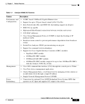
... Analyzer (SPAN) port monitoring on any port • Support for command switch redundancy • Support for optional Cisco 600W Redundant Power System (RPS) that operates on AC input and supplies DC output to four 1000BaseZX GBICs with the Catalyst 3508G XL switch) Management • Cisco IOS command-line interface (CLI) through the console port or Telnet •...
... Analyzer (SPAN) port monitoring on any port • Support for command switch redundancy • Support for optional Cisco 600W Redundant Power System (RPS) that operates on AC input and supplies DC output to four 1000BaseZX GBICs with the Catalyst 3508G XL switch) Management • Cisco IOS command-line interface (CLI) through the console port or Telnet •...

Installation Guide
Page 29
... set of LEDs and a Mode button. (The Catalyst 3548 XL switch has a Mode label that operates on AC input and supplies DC output to the Catalyst 3524-PWR XL switch Inline Power (Catalyst 3524-PWR XL switch only) • Ability to provide inline power for Cisco IP Phones from all 10/100 ports • ...Support for optional Cisco RPS 300 that you press.) These ...
... set of LEDs and a Mode button. (The Catalyst 3548 XL switch has a Mode label that operates on AC input and supplies DC output to the Catalyst 3524-PWR XL switch Inline Power (Catalyst 3524-PWR XL switch only) • Ability to provide inline power for Cisco IP Phones from all 10/100 ports • ...Support for optional Cisco RPS 300 that you press.) These ...
Installation Guide
Page 39
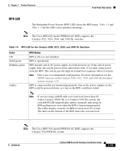
... Note The Cisco RPS 600 (model PWR600-AC-RPS) supports the Catalyst 3512, 3524, 3548, and 3508 XL switches. For more information see the "RPS Connector on the Catalyst 3508, 3512, 3524, and 3548 XL Switches" section on the bottom of the power supplies in the RPS could be powered down and ... 1-4 and Table 1-5 list the LED colors and their meanings. RPS and the switch AC power supply are using power from the RPS. The LEDs display correctly for the Catalyst 3508, 3512, 3524, and 3548 XL Switches Color Off Solid green Blinking green Amber RPS Status RPS is off or is operational...
... Note The Cisco RPS 600 (model PWR600-AC-RPS) supports the Catalyst 3512, 3524, 3548, and 3508 XL switches. For more information see the "RPS Connector on the Catalyst 3508, 3512, 3524, and 3548 XL Switches" section on the bottom of the power supplies in the RPS could be powered down and ... 1-4 and Table 1-5 list the LED colors and their meanings. RPS and the switch AC power supply are using power from the RPS. The LEDs display correctly for the Catalyst 3508, 3512, 3524, and 3548 XL Switches Color Off Solid green Blinking green Amber RPS Status RPS is off or is operational...
Installation Guide
Page 40
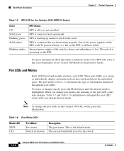
... about the failure conditions on the RPS. When you change the port mode in the RPS could have failed. Internal power supply of the power supplies in the Catalyst 3548 XL switch, press the Mode label. To select or change port modes, the meaning of information displayed through the port LEDs. Front.... RPS is the default mode. Table 1-6 Port Mode LEDs Mode LED STAT UTL Port Mode Port status Switch utilization Description The port status. RPS is operating on the Cisco RPS 300, refer to interpret the port LED colors after you change a mode, press the Mode button ...
... about the failure conditions on the RPS. When you change the port mode in the RPS could have failed. Internal power supply of the power supplies in the Catalyst 3548 XL switch, press the Mode label. To select or change port modes, the meaning of information displayed through the port LEDs. Front.... RPS is the default mode. Table 1-6 Port Mode LEDs Mode LED STAT UTL Port Mode Port status Switch utilization Description The port status. RPS is operating on the Cisco RPS 300, refer to interpret the port LED colors after you change a mode, press the Mode button ...

Installation Guide
Page 45
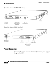
... Rear-Panel Description Rear-Panel Description Switch rear panels have an AC power connector, an RPS connector, and an RJ-45 console port (see Figure 1-17, Figure 1-19, Figure 1-18, and Figure 1-20), which are described in this section. Figure 1-17 Catalyst 3508G XL Rear Panel 18963 RATING ...DC INPUT +12V***@3A AC power connector RJ-45 console port Redundant power system connector Figure 1-18 Catalyst 3512 and 3524 XL Rear Panel Fans 18964 RATING 100-127/200-240V~ 1.0A/0.5A 50-60HZ AC power connector 78-6456-04 CONSOLE DC INPUTS FOR REMOTE POWER SUPPLY SPECIFIED IN MANUAL. +5V ...
... Rear-Panel Description Rear-Panel Description Switch rear panels have an AC power connector, an RPS connector, and an RJ-45 console port (see Figure 1-17, Figure 1-19, Figure 1-18, and Figure 1-20), which are described in this section. Figure 1-17 Catalyst 3508G XL Rear Panel 18963 RATING ...DC INPUT +12V***@3A AC power connector RJ-45 console port Redundant power system connector Figure 1-18 Catalyst 3512 and 3524 XL Rear Panel Fans 18964 RATING 100-127/200-240V~ 1.0A/0.5A 50-60HZ AC power connector 78-6456-04 CONSOLE DC INPUTS FOR REMOTE POWER SUPPLY SPECIFIED IN MANUAL. +5V ...
Installation Guide
Page 46
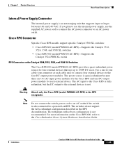
...~ 1.6A/0.9A 50-60HZ DC INPUTS FOR REMOTE POWER SUPPLY SPECIFIED IN MANUAL +3.3V @17A, +12 @1.1A CONSOLE AC power connector Fan exhaust RJ-45 console port Redundant power system connector Power Connectors You can provide power to the switch either through the internal power supply or through the Cisco RPS. 1-22 Catalyst 3500 Series XL Hardware Installation Guide 78-6456...
...~ 1.6A/0.9A 50-60HZ DC INPUTS FOR REMOTE POWER SUPPLY SPECIFIED IN MANUAL +3.3V @17A, +12 @1.1A CONSOLE AC power connector Fan exhaust RJ-45 console port Redundant power system connector Power Connectors You can provide power to the switch either through the internal power supply or through the Cisco RPS. 1-22 Catalyst 3500 Series XL Hardware Installation Guide 78-6456...
Installation Guide
Page 47
...you plan to use the internal power supply, use up to the external devices is not. Note Do not connect the switch power cord to an AC outlet if the switch is quasi-redundant because there are two AC input power modules for the Cisco RPS and one connector at each...AC power outlet. Cisco RPS Connector Specific Cisco RPS models support specific Catalyst 3500 XL switches: • Cisco RPS 600 (model PWR600-AC-RPS)-Supports the Catalyst 3512, 3524, 3548, and 3508 XL switches • Cisco RPS 300 (model PWR300-AC-RPS)-Supports the Catalyst 3524-PWR XL switch RPS Connector on the Cisco RPS ...
...you plan to use the internal power supply, use up to the external devices is not. Note Do not connect the switch power cord to an AC outlet if the switch is quasi-redundant because there are two AC input power modules for the Cisco RPS and one connector at each...AC power outlet. Cisco RPS Connector Specific Cisco RPS models support specific Catalyst 3500 XL switches: • Cisco RPS 600 (model PWR600-AC-RPS)-Supports the Catalyst 3512, 3524, 3548, and 3508 XL switches • Cisco RPS 300 (model PWR300-AC-RPS)-Supports the Catalyst 3524-PWR XL switch RPS Connector on the Cisco RPS ...
Installation Guide
Page 48
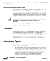
...six switches, it can connect a Catalyst 3500 XL switch to a PC by means of the console port and the supplied rollover cable and DB-9 adapter. For more than one switch fails at a time. You can order a kit (part number ACS-DSBUASYN=) containing that you want to connect the switch console... see the "Cable and Adapter Specifications" section on the Catalyst 3524-PWR XL Switch The Cisco RPS 300 (model PWR300-AC-RPS) has two output levels: -48V and 12V with a total output power of switches or an individual switch. You use the Visual Switch Manager (VSM) application to a terminal. You use the...
...six switches, it can connect a Catalyst 3500 XL switch to a PC by means of the console port and the supplied rollover cable and DB-9 adapter. For more than one switch fails at a time. You can order a kit (part number ACS-DSBUASYN=) containing that you want to connect the switch console... see the "Cable and Adapter Specifications" section on the Catalyst 3524-PWR XL Switch The Cisco RPS 300 (model PWR300-AC-RPS) has two output levels: -48V and 12V with a total output power of switches or an individual switch. You use the Visual Switch Manager (VSM) application to a terminal. You use the...

Installation Guide
Page 61
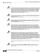
...Warning This product relies on /off switch. Statement 51 Warning Unplug the power cord before you work with TN power systems. Statement 19 Warning When installing ... Installation Warning To prevent the switch from overheating, do not operate it last. Statement 13 Warning This equipment is intended to be given to connecting units to the supply circuit so that a fuse ... 20 78-6456-04 Catalyst 3500 Series XL Hardware Installation Guide 2-3 Ensure that wiring is designed to earth ground during normal use. Chapter 2 Installing and Starting Up the Switch Preparing for short-circuit ...
...Warning This product relies on /off switch. Statement 51 Warning Unplug the power cord before you work with TN power systems. Statement 19 Warning When installing ... Installation Warning To prevent the switch from overheating, do not operate it last. Statement 13 Warning This equipment is intended to be given to connecting units to the supply circuit so that a fuse ... 20 78-6456-04 Catalyst 3500 Series XL Hardware Installation Guide 2-3 Ensure that wiring is designed to earth ground during normal use. Chapter 2 Installing and Starting Up the Switch Preparing for short-circuit ...
Installation Guide
Page 62
.... Preparing for Installation Chapter 2 Installing and Starting Up the Switch Warning Do not touch the power supply when the power cord is removed from the DC circuit. Statement 1072 The following warning applies to the Catalyst 3508, 3512, 3524, and 3548 XL switches: Warning Attach only the Cisco RPS (model PWR600-AC-RPS) to the RPS receptacle.
.... Preparing for Installation Chapter 2 Installing and Starting Up the Switch Warning Do not touch the power supply when the power cord is removed from the DC circuit. Statement 1072 The following warning applies to the Catalyst 3508, 3512, 3524, and 3548 XL switches: Warning Attach only the Cisco RPS (model PWR600-AC-RPS) to the RPS receptacle.

Installation Guide
Page 71
... the cables from obscuring the front panel of POST tests described in the "Powering On the Switch and Running POST" section on page 2-17. Attaching the Optional Cable Guide ... 78-6456-04 Catalyst 3500 Series XL Hardware Installation Guide 2-13 If the switch is in a 19-inch or 24-inch rack, use the four supplied number-12 Phillips machine...switch is connected, the System LED turns amber for installation instructions. Chapter 2 Installing and Starting Up the Switch Installing the Switch in a Rack Mounting the Switch in a Rack After the brackets are using the Cisco RPS, see the Cisco...
... the cables from obscuring the front panel of POST tests described in the "Powering On the Switch and Running POST" section on page 2-17. Attaching the Optional Cable Guide ... 78-6456-04 Catalyst 3500 Series XL Hardware Installation Guide 2-13 If the switch is in a 19-inch or 24-inch rack, use the four supplied number-12 Phillips machine...switch is connected, the System LED turns amber for installation instructions. Chapter 2 Installing and Starting Up the Switch Installing the Switch in a Rack Mounting the Switch in a Rack After the brackets are using the Cisco RPS, see the Cisco...
Installation Guide
Page 74
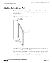
... on page 2-17. 2-16 Catalyst 3500 Series XL Hardware Installation Guide 78-6456-04 Installing the Switch on a Wall Chapter 2 Installing and Starting Up the Switch Attaching the Switch to the switch. If you are using the RPS, see the Cisco RPS documentation. Figure 2-9 Attaching the Switch to a Wall Vertical wall stud 8 User-supplied screws 7 6 5 4 3 2 Vertical wall-mount...
... on page 2-17. 2-16 Catalyst 3500 Series XL Hardware Installation Guide 78-6456-04 Installing the Switch on a Wall Chapter 2 Installing and Starting Up the Switch Attaching the Switch to the switch. If you are using the RPS, see the Cisco RPS documentation. Figure 2-9 Attaching the Switch to a Wall Vertical wall stud 8 User-supplied screws 7 6 5 4 3 2 Vertical wall-mount...

Installation Guide
Page 82
... connector into the console port, as shown in the switch • Using a BOOTP server This section describes each method. 2-24 Catalyst 3500 Series XL Hardware Installation Guide 78-6456-04 Figure 2-13 Connecting to the Console Port 32709 CONSOLE DC INPUTS FOR REMOTE POWER SUPPLY SPECIFIED IN MANUAL. +5V @24A, +12V @1.0A RJ-45...
... connector into the console port, as shown in the switch • Using a BOOTP server This section describes each method. 2-24 Catalyst 3500 Series XL Hardware Installation Guide 78-6456-04 Figure 2-13 Connecting to the Console Port 32709 CONSOLE DC INPUTS FOR REMOTE POWER SUPPLY SPECIFIED IN MANUAL. +5V @24A, +12V @1.0A RJ-45...

Installation Guide
Page 137
Appendix C Translated Safety Warnings Power Supply Warning 78-6456-04 Catalyst 3500 Series XL Hardware Installation Guide C-29
Appendix C Translated Safety Warnings Power Supply Warning 78-6456-04 Catalyst 3500 Series XL Hardware Installation Guide C-29

Installation Guide
Page 157
... 2-24 installation 2-7 to 2-17 IP address 2-24 product disposal warning C-31 PSTN 1-33 publications, related xviii Public Switched Telephone Network See PSTN Q qualified personnel warning C-7 R rack installation 2-9 bracket mounting points 2-10 rack-mounting 2-13 rear panel 1-21 to 1-22 clearance 2-8 Redundant Power Supply 78-6456-04 Catalyst 3500 Series XL Hardware Installation Guide IN-5
... 2-24 installation 2-7 to 2-17 IP address 2-24 product disposal warning C-31 PSTN 1-33 publications, related xviii Public Switched Telephone Network See PSTN Q qualified personnel warning C-7 R rack installation 2-9 bracket mounting points 2-10 rack-mounting 2-13 rear panel 1-21 to 1-22 clearance 2-8 Redundant Power Supply 78-6456-04 Catalyst 3500 Series XL Hardware Installation Guide IN-5
Installation Guide
Page 158
... Manager 1-25 supply circuit warning C-24 switch applications 1-25 startup powering on 2-17 system LED 1-14 T table-mounting 2-17 technical specifications A-1 Telnet, and accessing the CLI 1-25 temperature operating A-1 warning C-16 terminal, connecting to switch 2-23 terminal emulation software 2-23 TN power warning C-19 translated warnings C-1 troubleshooting 3-1 to 3-5 U UTL LED 1-16, 1-17 IN-6 Catalyst 3500 Series...
... Manager 1-25 supply circuit warning C-24 switch applications 1-25 startup powering on 2-17 system LED 1-14 T table-mounting 2-17 technical specifications A-1 Telnet, and accessing the CLI 1-25 temperature operating A-1 warning C-16 terminal, connecting to switch 2-23 terminal emulation software 2-23 TN power warning C-19 translated warnings C-1 troubleshooting 3-1 to 3-5 U UTL LED 1-16, 1-17 IN-6 Catalyst 3500 Series...

