Hardware Installation Guide
Page 4
Contents 2 C H A P T E R 3 C H A P T E R Cisco 3660 Interfaces 1-11 Slot Numbering 1-11 Voice Interface Numbering 1-12 System Specifications 1-12 Regulatory Compliance 1-15 Preparing to Install the Router 2-1 Safety Recommendations 2-1 Safety ...DTE or DCE Devices 2-11 Signaling Standards Supported 2-12 Distance Limitations 2-12 Asynchronous/Synchronous Serial Module Baud Rates 2-13 ISDN BRI Connections 2-13 56-K/Switched-56-kbps DSU/CSU Connections 2-14 Installing the Router 3-1 Installing Modules, Interface Cards, and Power Supplies 3-2 Installing the Chassis 3-3 Setting the Chassis on ...
Contents 2 C H A P T E R 3 C H A P T E R Cisco 3660 Interfaces 1-11 Slot Numbering 1-11 Voice Interface Numbering 1-12 System Specifications 1-12 Regulatory Compliance 1-15 Preparing to Install the Router 2-1 Safety Recommendations 2-1 Safety ...DTE or DCE Devices 2-11 Signaling Standards Supported 2-12 Distance Limitations 2-12 Asynchronous/Synchronous Serial Module Baud Rates 2-13 ISDN BRI Connections 2-13 56-K/Switched-56-kbps DSU/CSU Connections 2-14 Installing the Router 3-1 Installing Modules, Interface Cards, and Power Supplies 3-2 Installing the Chassis 3-3 Setting the Chassis on ...
Hardware Installation Guide
Page 38
...is available, ground yourself by touching a metal part of the antistatic strap. It should be between 1 and 10 megohms (Mohm). Cisco 3600 Series Routers Hardware Installation Guide 2-2 OL-2056-05 Working near power supplies • Look carefully for possible hazards in your equipment..., periodically check the resistance value of the chassis. Turn off switch in the room in wet locations unless the jack is disconnected from a circuit. In addition, use the following : - Installing or removing ...
...is available, ground yourself by touching a metal part of the antistatic strap. It should be between 1 and 10 megohms (Mohm). Cisco 3600 Series Routers Hardware Installation Guide 2-2 OL-2056-05 Working near power supplies • Look carefully for possible hazards in your equipment..., periodically check the resistance value of the chassis. Turn off switch in the room in wet locations unless the jack is disconnected from a circuit. In addition, use the following : - Installing or removing ...
Hardware Installation Guide
Page 46
...8226; Token Ring Connections, page 2-11 • Serial Connections, page 2-11 • ISDN BRI Connections, page 2-13 • 56-K/Switched-56-kbps DSU/CSU Connections, page 2-14 Refer to the following online documents for more information about Ethernet cables, connectors, and pinouts. ... look like the wiring used for information about network connections and interfaces: • Cisco Network Modules Hardware Installation Guide • Cisco Interface Cards Installation Guide • Cisco Modular Access Router Cable Specifications Warning To avoid electric shock, do not meet certain ...
...8226; Token Ring Connections, page 2-11 • Serial Connections, page 2-11 • ISDN BRI Connections, page 2-13 • 56-K/Switched-56-kbps DSU/CSU Connections, page 2-14 Refer to the following online documents for more information about Ethernet cables, connectors, and pinouts. ... look like the wiring used for information about network connections and interfaces: • Cisco Network Modules Hardware Installation Guide • Cisco Interface Cards Installation Guide • Cisco Modular Access Router Cable Specifications Warning To avoid electric shock, do not meet certain ...
Hardware Installation Guide
Page 47
...Token Ring must use DB-60 connectors. For more information on WAN interface cards, refer to DCE devices. OL-2056-05 Cisco 3600 Series Routers Hardware Installation Guide 2-11 Note To ensure agency compliance with FCC Class B electromagnetic emissions requirements (EMI), make ...depending on the serial cable used. For more information on network modules, refer to a switch. A DCE device provides a clock signal that you are accessible online and on the Cisco Documentation CD-ROM. The documentation that communicates over a synchronous serial interface is available online and...
...Token Ring must use DB-60 connectors. For more information on WAN interface cards, refer to DCE devices. OL-2056-05 Cisco 3600 Series Routers Hardware Installation Guide 2-11 Note To ensure agency compliance with FCC Class B electromagnetic emissions requirements (EMI), make ...depending on the serial cable used. For more information on network modules, refer to a switch. A DCE device provides a clock signal that you are accessible online and on the Cisco Documentation CD-ROM. The documentation that communicates over a synchronous serial interface is available online and...

Hardware Installation Guide
Page 50
This document is located on Cisco.com and the Documentation CD-ROM. 2-14 Cisco 3600 Series Routers Hardware Installation Guide OL-2056-05 This document is located on Cisco.com and the Documentation CD-ROM. 56-K/Switched-56-kbps DSU/CSU Connections Switched-56-kbps connections are provided by the ...56-kbps DSU/CSU WAN interface card. For more information on Switched-56-kbps WAN interface cards, refer to the Cisco Interface Cards Installation Guide online document. nF = nanoFarad High-Capacitance Cable Low-Capacitance Cable 160 ohms/km 120 nF1/...
This document is located on Cisco.com and the Documentation CD-ROM. 2-14 Cisco 3600 Series Routers Hardware Installation Guide OL-2056-05 This document is located on Cisco.com and the Documentation CD-ROM. 56-K/Switched-56-kbps DSU/CSU Connections Switched-56-kbps connections are provided by the ...56-kbps DSU/CSU WAN interface card. For more information on Switched-56-kbps WAN interface cards, refer to the Cisco Interface Cards Installation Guide online document. nF = nanoFarad High-Capacitance Cable Low-Capacitance Cable 160 ohms/km 120 nF1/...

Hardware Installation Guide
Page 78
... the DC circuit, locate the circuit breaker for the DC circuit, switch the circuit breaker to the OFF position, and tape the circuit-breaker switch in this unit to the appropriate length for proper wiring. Step 2 For Cisco 3620 routers, strip the wires to avoid disturbing field-wiring connections. ...Routers, page 3-28 • Wiring the DC-Input Power Supply in Cisco 3631 Routers, page 3-30 • Wiring the DC-Input Power Supply in Cisco 3660 Routers, page 3-32 Wiring the DC-Input Power Supply in Cisco 3620 and Cisco 3640 Routers If your router has a DC-input power supply, follow the...
... the DC circuit, locate the circuit breaker for the DC circuit, switch the circuit breaker to the OFF position, and tape the circuit-breaker switch in this unit to the appropriate length for proper wiring. Step 2 For Cisco 3620 routers, strip the wires to avoid disturbing field-wiring connections. ...Routers, page 3-28 • Wiring the DC-Input Power Supply in Cisco 3631 Routers, page 3-30 • Wiring the DC-Input Power Supply in Cisco 3660 Routers, page 3-32 Wiring the DC-Input Power Supply in Cisco 3620 and Cisco 3640 Routers If your router has a DC-input power supply, follow the...
Hardware Installation Guide
Page 79
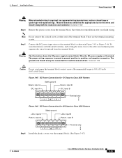
...to the DC circuit. Caution Do not overtorque the terminal block captive thumbscrew or terminal block contact screws. OL-2056-05 Cisco 3600 Series Routers Hardware Installation Guide 3-29 The recommended torque is ground to ground, positive to positive, and negative to the.... Figure 3-43 DC Power Connections for Cisco 3640 Routers (Typical) Negative Terminal block Ground Terminal block Positive On/off switch +- Terminal block Positive Negative Ground Figure 3-44 DC Power Connections for Cisco 3620 Routers (Typical) On/off switch H7477 72331 Step 4 Secure the wires using...
...to the DC circuit. Caution Do not overtorque the terminal block captive thumbscrew or terminal block contact screws. OL-2056-05 Cisco 3600 Series Routers Hardware Installation Guide 3-29 The recommended torque is ground to ground, positive to positive, and negative to the.... Figure 3-43 DC Power Connections for Cisco 3640 Routers (Typical) Negative Terminal block Ground Terminal block Positive On/off switch +- Terminal block Positive Negative Ground Figure 3-44 DC Power Connections for Cisco 3620 Routers (Typical) On/off switch H7477 72331 Step 4 Secure the wires using...

Hardware Installation Guide
Page 80
... the DC circuit. Crimp the terminals to the appropriate length for proper wiring. Step 2 Step 3 Strip the wires to the DC power input wires. 3-30 Cisco 3600 Series Routers Hardware Installation Guide OL-2056-05 Power Connections Chapter 3 Installing the Router Wiring the DC-Input Power Supply in... DC circuit, locate the circuit breaker for nominal 48-V power supplies are 38 and 72 VDC. The input voltage tolerance limits for the DC circuit, switch the circuit breaker to the OFF position, and tape the circuit-breaker switch in this unit to either the A input or the B input.
... the DC circuit. Crimp the terminals to the appropriate length for proper wiring. Step 2 Step 3 Strip the wires to the DC power input wires. 3-30 Cisco 3600 Series Routers Hardware Installation Guide OL-2056-05 Power Connections Chapter 3 Installing the Router Wiring the DC-Input Power Supply in... DC circuit, locate the circuit breaker for nominal 48-V power supplies are 38 and 72 VDC. The input voltage tolerance limits for the DC circuit, switch the circuit breaker to the OFF position, and tape the circuit-breaker switch in this unit to either the A input or the B input.
Hardware Installation Guide
Page 81
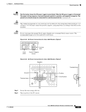
... the plastic covers from the terminal block. Wire the DC power supply as closed-loop or spade-type with the on/off switches, and to bring the wires close to negative. Warning The illustration shows the DC power supply terminal block. The ground wire should ...B -DC, input B 88135 A+ +B Terminal strip Figure 3-46 DC Power Connections for reinstallation after you finish wiring. Step 5 Connect the DC power input wires to Cisco 3631 Routers +DC, input A Return, input A Safety ground +DC, input B Return, input B 88136 A+ +B Terminal strip Step 6 Install the plastic covers over ...
... the plastic covers from the terminal block. Wire the DC power supply as closed-loop or spade-type with the on/off switches, and to bring the wires close to negative. Warning The illustration shows the DC power supply terminal block. The ground wire should ...B -DC, input B 88135 A+ +B Terminal strip Figure 3-46 DC Power Connections for reinstallation after you finish wiring. Step 5 Connect the DC power input wires to Cisco 3631 Routers +DC, input A Return, input A Safety ground +DC, input B Return, input B 88136 A+ +B Terminal strip Step 6 Install the plastic covers over ...
Hardware Installation Guide
Page 83
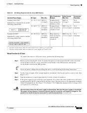
...field-wiring connections. The proper wiring sequence is removed from the DC circuit. The input voltage tolerance limits for the DC circuit, switch the circuit breaker to a torque of conductor. Warning The illustration shows the DC power supply terminal block. wires retained by a ... 2.0 mm2) maximum AC PS 100-240V~, 4-2A, 50/60 Hz DC PS -48V to negative. The input voltage tolerance limits for Cisco 3660 Routers Installed Power Supply Nominal 24/48 VDC1 Identified by retention screws Terminal block; Chapter 3 Installing the Router Power Connections Table 3-3 DC Wiring...
...field-wiring connections. The proper wiring sequence is removed from the DC circuit. The input voltage tolerance limits for the DC circuit, switch the circuit breaker to a torque of conductor. Warning The illustration shows the DC power supply terminal block. wires retained by a ... 2.0 mm2) maximum AC PS 100-240V~, 4-2A, 50/60 Hz DC PS -48V to negative. The input voltage tolerance limits for Cisco 3660 Routers Installed Power Supply Nominal 24/48 VDC1 Identified by retention screws Terminal block; Chapter 3 Installing the Router Power Connections Table 3-3 DC Wiring...
Hardware Installation Guide
Page 102
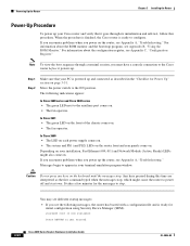
... 2 Make sure that it powers up. For information about the ROM monitor and the bootstrap program, see Appendix A, "Troubleshooting." Move the power switch to appear in the "Checklist for Power Up" section on . yourname con0 is powered up and connected as the first command typed when the .... If you encounter problems when you see Appendix A, "Troubleshooting." It takes a few minutes for initial configuration using Security Device Manager (SDM). In Cisco 3660 • The LED on each power supply comes on. • The system and PS1 (and PS2) LEDs on the router front and rear ...
... 2 Make sure that it powers up. For information about the ROM monitor and the bootstrap program, see Appendix A, "Troubleshooting." Move the power switch to appear in the "Checklist for Power Up" section on . yourname con0 is powered up and connected as the first command typed when the .... If you encounter problems when you see Appendix A, "Troubleshooting." It takes a few minutes for initial configuration using Security Device Manager (SDM). In Cisco 3660 • The LED on each power supply comes on. • The system and PS1 (and PS2) LEDs on the router front and rear ...
Hardware Installation Guide
Page 110
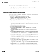
...Also consider inadequate ventilation or air circulation. • Modules-LEDs on the modules can help isolate the problem: • With the power switch on, does the system LED stay on the Documentation CD-ROM and online. Isolating Problems Appendix A Troubleshooting When problem solving, consider the ...functional. - For an explanation of the router. If they are green, the power supplies are connected directly to the warranty information in the Cisco 3660 router by inspecting the system LED on page 2-3. - If yes, the router is functional. - If the system LED is on , ...
...Also consider inadequate ventilation or air circulation. • Modules-LEDs on the modules can help isolate the problem: • With the power switch on, does the system LED stay on the Documentation CD-ROM and online. Isolating Problems Appendix A Troubleshooting When problem solving, consider the ...functional. - For an explanation of the router. If they are green, the power supplies are connected directly to the warranty information in the Cisco 3660 router by inspecting the system LED on page 2-3. - If yes, the router is functional. - If the system LED is on , ...
Hardware Installation Guide
Page 137
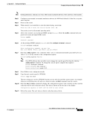
... Reboot the router. Enter the show version command to change the console speed, complete this publication, references to Cisco 3660 routers include both Cisco 3661 and Cisco 3662 models. OL-2056-05 Cisco 3600 Series Routers Hardware Installation Guide C-3 Step 2 Step 3 Step 4 Step 5 Step 6 Step 7 Configure...be 0x142 at the next reload. Enter the enable command and your terminal or terminal emulation software for example, when you switch the power off and on the router. Appendix C Configuration Register Changing Configuration Register Settings Note In this sequence: Router# configure...
... Reboot the router. Enter the show version command to change the console speed, complete this publication, references to Cisco 3660 routers include both Cisco 3661 and Cisco 3662 models. OL-2056-05 Cisco 3600 Series Routers Hardware Installation Guide C-3 Step 2 Step 3 Step 4 Step 5 Step 6 Step 7 Configure...be 0x142 at the next reload. Enter the enable command and your terminal or terminal emulation software for example, when you switch the power off and on the router. Appendix C Configuration Register Changing Configuration Register Settings Note In this sequence: Router# configure...


