
Quick Start Guide
Page 4
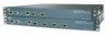
... to install and configure a controller. Cisco 4402 controllers have four gigabit Ethernet distribution system ports, each of which is capable of managing up to 48 access points. Cisco 4404 controllers have two gigabit Ethernet distribution system...controller. Figure 1 Front Panel Layout 155837 LINK ACT SERVICE CONSOLE STATUS ALARM LINK PS1 PS2 UTILITY ACT LINK ACT 1 2 1 2 3 4 56 7 LINK ACT 3 4 8 9 10 1 Service port (RJ-45) 6 Distribution port 1 & 2 Link and Activity LEDs 2 Console port (DB-9 female) 7 Distribution port 2 3 Status, alarm, and power supply...
... to install and configure a controller. Cisco 4402 controllers have four gigabit Ethernet distribution system ports, each of which is capable of managing up to 48 access points. Cisco 4404 controllers have two gigabit Ethernet distribution system...controller. Figure 1 Front Panel Layout 155837 LINK ACT SERVICE CONSOLE STATUS ALARM LINK PS1 PS2 UTILITY ACT LINK ACT 1 2 1 2 3 4 56 7 LINK ACT 3 4 8 9 10 1 Service port (RJ-45) 6 Distribution port 1 & 2 Link and Activity LEDs 2 Console port (DB-9 female) 7 Distribution port 2 3 Status, alarm, and power supply...

Quick Start Guide
Page 5
... port. Off indicates normal operation. Figure 2 Back Panel Layout 155923 1 2 3 45 6 1 VPN termination module Slot 1 2 VPN termination module slot 0 3 Power supply slot 1 4 Slot 2 power supply power receptacle 5 Slot 2 power supply switch 6 Slot 2 power supply LED Checking the Controller LEDs If your controller is operational. Off indicates normal operation. Solid green indicates Ethernet link to quickly assess the unit's status. Blinking green...
... port. Off indicates normal operation. Figure 2 Back Panel Layout 155923 1 2 3 45 6 1 VPN termination module Slot 1 2 VPN termination module slot 0 3 Power supply slot 1 4 Slot 2 power supply power receptacle 5 Slot 2 power supply switch 6 Slot 2 power supply LED Checking the Controller LEDs If your controller is operational. Off indicates normal operation. Solid green indicates Ethernet link to quickly assess the unit's status. Blinking green...
Quick Start Guide
Page 6
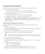
...Blinking green indicates data transmission on distribution port # link. Package Contents Each access point package contains the following items: • Cisco 4400 series wireless LAN controller and power cord • Mounting hardware kit • Translated Safety Warnings for operation: Step 1 Step 2 Step 3 Open the shipping container..." section are included in the shipment. If any item is damaged or missing, notify your authorized Cisco sales representative. Rear Panel LEDs LED Description Power supply unit Solid white indicates normal operation. Check each item for damage.
...Blinking green indicates data transmission on distribution port # link. Package Contents Each access point package contains the following items: • Cisco 4400 series wireless LAN controller and power cord • Mounting hardware kit • Translated Safety Warnings for operation: Step 1 Step 2 Step 3 Open the shipping container..." section are included in the shipment. If any item is damaged or missing, notify your authorized Cisco sales representative. Rear Panel LEDs LED Description Power supply unit Solid white indicates normal operation. Check each item for damage.
Quick Start Guide
Page 7
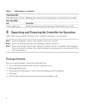
...line interface (CLI) console - Controller with factory-supplied power cord and mounting hardware - This means that will need the following initial configuration parameters from your wireless LAN or network administrator: • A system (controller name). • An administrative ... panel GigE ports - 4404: 1-4 for downloading operating system software updates). Cisco uses an integral TFTP server. Initial System Configuration Information Obtain the following tools and information before you can install the controller: • Wireless LAN controller hardware - Network, operating...
...line interface (CLI) console - Controller with factory-supplied power cord and mounting hardware - This means that will need the following initial configuration parameters from your wireless LAN or network administrator: • A system (controller name). • An administrative ... panel GigE ports - 4404: 1-4 for downloading operating system software updates). Cisco uses an integral TFTP server. Initial System Configuration Information Obtain the following tools and information before you can install the controller: • Wireless LAN controller hardware - Network, operating...
Quick Start Guide
Page 9
... links using LC physical connectors. If desired, you have purchased an extra power supply module or enhanced security modules, refer to the Cisco 4400 Series Power Supply Quick Start Guide for information about installing these guidelines when mounting the controller: • When mounting the controller on a desktop or shelf, attach the rubber feet to the bottom of...
... links using LC physical connectors. If desired, you have purchased an extra power supply module or enhanced security modules, refer to the Cisco 4400 Series Power Supply Quick Start Guide for information about installing these guidelines when mounting the controller: • When mounting the controller on a desktop or shelf, attach the rubber feet to the bottom of...
Quick Start Guide
Page 10
... as described in the "Connecting the Controller's Console Port" section on page 10. Start the PC's terminal emulation program. Configure the terminal emulation program for basic operations, you should have more than one power supply connection. Warning This unit might have ...connected your PC to the controller's CLI console as HyperTerminal, ProComm, Minicom, or Tip). All connections must be removed to...
... as described in the "Connecting the Controller's Console Port" section on page 10. Start the PC's terminal emulation program. Configure the terminal emulation program for basic operations, you should have more than one power supply connection. Warning This unit might have ...connected your PC to the controller's CLI console as HyperTerminal, ProComm, Minicom, or Tip). All connections must be removed to...
Quick Start Guide
Page 13
...Starting Switching Services: ok Starting QoS Services: ok Starting Policy Manager: ok Starting Data Transport Link Layer: ok Starting Access Control List Services: ok Starting System Interfaces: ok Starting LWAPP: ok Starting Crypto Accelerator[s]: None Present Starting Certificate Database: ok Starting... Starting IDS Signature Manager: ok Starting External Policy Interface: ok Starting RFID Tag Tracking: ok Starting Power Supply and Fan Status Monitoring Service: ok Starting WLAN Control Protocol (WCP): wcpSysInit: Out of factory boot: Initialize ports and IP address for interfaces wcpSysInit: ...
...Starting Switching Services: ok Starting QoS Services: ok Starting Policy Manager: ok Starting Data Transport Link Layer: ok Starting Access Control List Services: ok Starting System Interfaces: ok Starting LWAPP: ok Starting Crypto Accelerator[s]: None Present Starting Certificate Database: ok Starting... Starting IDS Signature Manager: ok Starting External Policy Interface: ok Starting RFID Tag Tracking: ok Starting Power Supply and Fan Status Monitoring Service: ok Starting WLAN Control Protocol (WCP): wcpSysInit: Out of factory boot: Initialize ports and IP address for interfaces wcpSysInit: ...

Quick Start Guide
Page 19
... allowing clients to power the controller should the other power supply unit fail. Either power supply continues to associate. As soon as the controller is optional. you must first connect the PC to the switch's service port in one or both power supplies. 19 Refer to the Cisco Wireless LAN Controller Configuration Guide, Release 3.4, for basic operation. Installing a Power Supply Unit The controller can perform out...
... allowing clients to power the controller should the other power supply unit fail. Either power supply continues to associate. As soon as the controller is optional. you must first connect the PC to the switch's service port in one or both power supplies. 19 Refer to the Cisco Wireless LAN Controller Configuration Guide, Release 3.4, for basic operation. Installing a Power Supply Unit The controller can perform out...

Quick Start Guide
Page 20
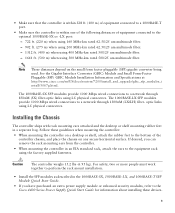
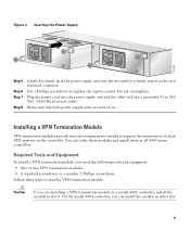
... 3 Step 4 Use a Phillips screwdriver to install a power supply unit. Align the power supply unit with the slot so that the unit's power input receptacle is installed in slot 2 at the factory. You can order a second power supply unit and install it in slot 1. Step 1 Locate the empty power supply slot on the controller's back panel. Remove the slot cover and...
... 3 Step 4 Use a Phillips screwdriver to install a power supply unit. Align the power supply unit with the slot so that the unit's power input receptacle is installed in slot 2 at the factory. You can order a second power supply unit and install it in slot 1. Step 1 Locate the empty power supply slot on the controller's back panel. Remove the slot cover and...
Quick Start Guide
Page 21
... into a grounded 95 to 260 VAC 50/60 Hz electrical outlet. Make sure that both power supply units are installing a VPN termination module in a model 4402 controller, install the module in all 4400 series controllers. On the model 4404 controller, you need the following tools and equipment: • One or two VPN termination modules. • A standard...
... into a grounded 95 to 260 VAC 50/60 Hz electrical outlet. Make sure that both power supply units are installing a VPN termination module in a model 4402 controller, install the module in all 4400 series controllers. On the model 4404 controller, you need the following tools and equipment: • One or two VPN termination modules. • A standard...
Quick Start Guide
Page 22
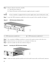
...card electrical connector. 22 Insert the module into the slot until it in Figure 6. b. Caution If your controller is equipped with two power supply units, remove both power cords. Turn the power switch off. Figure 5 VPN Termination Module Slots 146191 1 2 1 VPN termination module slot 1 2 VPN... 5 Use a standard or Phillips screwdriver to unscrew the captive screws on the rear panel of the controller. See Figure 5. a. Step 1 Remove all power from the power supply unit power receptacle. Step 2 Locate the VPN termination module slot on the slot cover. Figure 6 Inserting the ...
...card electrical connector. 22 Insert the module into the slot until it in Figure 6. b. Caution If your controller is equipped with two power supply units, remove both power cords. Turn the power switch off. Figure 5 VPN Termination Module Slots 146191 1 2 1 VPN termination module slot 1 2 VPN... 5 Use a standard or Phillips screwdriver to unscrew the captive screws on the rear panel of the controller. See Figure 5. a. Step 1 Remove all power from the power supply unit power receptacle. Step 2 Locate the VPN termination module slot on the slot cover. Figure 6 Inserting the ...

Quick Start Guide
Page 23
..., and go to Cisco software, is equipped with two power supply units, insert both power cords. c. Do not overtighten. b. Restore all new and revised Cisco technical documentation, at: http://www.cisco.com/en/US/docs/general/whatsnew/whatsnew.html Subscribe to tighten the captive screws. a. Plug the power cords into the controller power supply unit. Turn the power supply units on. 5 Obtaining...
..., and go to Cisco software, is equipped with two power supply units, insert both power cords. c. Do not overtighten. b. Restore all new and revised Cisco technical documentation, at: http://www.cisco.com/en/US/docs/general/whatsnew/whatsnew.html Subscribe to tighten the captive screws. a. Plug the power cords into the controller power supply unit. Turn the power supply units on. 5 Obtaining...
