
Installation Guide
Page 6
... to the Switch 3-11 Transceiver Modules 4-1 SFP Modules 4-1 SFP Modules and Alternative Wiring 4-1 X2 Modules 4-2 Module Maintenance Guidelines 4-5 Cleaning the Fiber-Optic Connectors 4-5 Additional Guidelines 4-7 Troubleshooting the Installation 5-1 Getting Started 5-2 Problem Solving to the System Component Level 5-2 Identifying Startup Problems 5-3 LED Readings 5-3 Troubleshooting the Power Supply 5-5 Contacting Customer Service 5-6 Specifications A-1 Console Port A-1 Catalyst 4900 Series Switch Installation Guide...
... to the Switch 3-11 Transceiver Modules 4-1 SFP Modules 4-1 SFP Modules and Alternative Wiring 4-1 X2 Modules 4-2 Module Maintenance Guidelines 4-5 Cleaning the Fiber-Optic Connectors 4-5 Additional Guidelines 4-7 Troubleshooting the Installation 5-1 Getting Started 5-2 Problem Solving to the System Component Level 5-2 Identifying Startup Problems 5-3 LED Readings 5-3 Troubleshooting the Power Supply 5-5 Contacting Customer Service 5-6 Specifications A-1 Console Port A-1 Catalyst 4900 Series Switch Installation Guide...

Installation Guide
Page 9
... to install, remove, and maintain transceiver modules. 78-18039-02 Catalyst 4900 Series Switch Installation Guide ix Transceiver Modules Describes how to install the switch. Audience Only trained and qualified service personnel (as follows: Title Description Product Overview Describes the hardware features and functionality of the Catalyst 4900 series switches. Site Planning Describes how to prepare your...
... to install, remove, and maintain transceiver modules. 78-18039-02 Catalyst 4900 Series Switch Installation Guide ix Transceiver Modules Describes how to install the switch. Audience Only trained and qualified service personnel (as follows: Title Description Product Overview Describes the hardware features and functionality of the Catalyst 4900 series switches. Site Planning Describes how to prepare your...
Installation Guide
Page 26
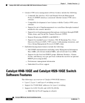
... overview of Catalyst 4948-10GE features: • Layer 2, Layer 3, and Layer 4 switching services • Support for 55,000 MAC addresses for Layer 2 switching • Support for 4,096 VLANs and 4,096 VLAN IDs - Support for standard Layer 2 features: 802.1D Spanning Tree, Cisco Discovery Protocol (CDP), VTP version 2 with RMON-1 - Support for an optional RMON processing module - Support...
... overview of Catalyst 4948-10GE features: • Layer 2, Layer 3, and Layer 4 switching services • Support for 55,000 MAC addresses for Layer 2 switching • Support for 4,096 VLANs and 4,096 VLAN IDs - Support for standard Layer 2 features: 802.1D Spanning Tree, Cisco Discovery Protocol (CDP), VTP version 2 with RMON-1 - Support for an optional RMON processing module - Support...

Installation Guide
Page 27
... (CLI) and Simple Network Management Protocol (SNMP) interfaces consistent with the Catalyst 4500 series switches - Performance management information - Support for out-of new features with the Catalyst 4500 series switches - Chapter 1 Product Overview Catalyst 4948-10GE and Catalyst 4928-10GE Switch Software Features - Remote Monitoring (RMON) with pruning extensions, and Cisco Group Management Protocol (CGMP) client • Embedded management features include...
... (CLI) and Simple Network Management Protocol (SNMP) interfaces consistent with the Catalyst 4500 series switches - Performance management information - Support for out-of new features with the Catalyst 4500 series switches - Chapter 1 Product Overview Catalyst 4948-10GE and Catalyst 4928-10GE Switch Software Features - Remote Monitoring (RMON) with pruning extensions, and Cisco Group Management Protocol (CGMP) client • Embedded management features include...

Installation Guide
Page 37
... an enclosed, secure area, ensuring that is provided on page 3-5 to maintain. 78-18039-02 Catalyst 4900 Series Switch Installation Guide 2-1 Site Planning 2 C H A P T E R This chapter describes how to the switch and control of the switch and contains these sections: • Site Environmental Requirements, page 2-1 • Site Power Requirements, page 2-2 • Grounding Requirements, page 2-6 •...
... an enclosed, secure area, ensuring that is provided on page 3-5 to maintain. 78-18039-02 Catalyst 4900 Series Switch Installation Guide 2-1 Site Planning 2 C H A P T E R This chapter describes how to the switch and control of the switch and contains these sections: • Site Environmental Requirements, page 2-1 • Site Power Requirements, page 2-2 • Grounding Requirements, page 2-6 •...

Installation Guide
Page 45
...be between 1 and 10 megohms (Mohms). • Handle cards by the edges only. • Avoid contact between the modules and clothing. ESD voltages on the chassis or equipment rack Caution Periodically check the resistance value of the following: - Site Planning... Checklist Table 2-2 lists the site planning activities that creates a potential hazard to ensure a successful switch installation. 78-18039-02 Catalyst 4900 Series Switch Installation Guide 2-9 Any unpainted grounded surface on clothing can result in complete or intermittent failures. Completing each activity...
...be between 1 and 10 megohms (Mohms). • Handle cards by the edges only. • Avoid contact between the modules and clothing. ESD voltages on the chassis or equipment rack Caution Periodically check the resistance value of the following: - Site Planning... Checklist Table 2-2 lists the site planning activities that creates a potential hazard to ensure a successful switch installation. 78-18039-02 Catalyst 4900 Series Switch Installation Guide 2-9 Any unpainted grounded surface on clothing can result in complete or intermittent failures. Completing each activity...

Installation Guide
Page 50
... chassis with stabilizing devices). • The equipment rack is too powerful might be higher than the ambient room temperature. - Catalyst 4900 Series Switch Installation Guide 3-4 78-18039-02 Consider the equipment and cabling that cables from other equipment will not obstruct the airflow through... not exceed a maximum temperature of the chassis. - Use baffles correctly to the power supplies or switching modules. Install the stabilizers before mounting or servicing the switch in an enclosed rack only if it out when necessary for normal operation and pull it has adequate...
... chassis with stabilizing devices). • The equipment rack is too powerful might be higher than the ambient room temperature. - Catalyst 4900 Series Switch Installation Guide 3-4 78-18039-02 Consider the equipment and cabling that cables from other equipment will not obstruct the airflow through... not exceed a maximum temperature of the chassis. - Use baffles correctly to the power supplies or switching modules. Install the stabilizers before mounting or servicing the switch in an enclosed rack only if it out when necessary for normal operation and pull it has adequate...

Installation Guide
Page 61
... SFP compatibility, refer to configure the media type for these switches are laser optical transceivers used to the relevant documents at the following location: http://www.cisco.com/en/US/products/hw/modules/ps5455/products_device_sup port_tables_list.html SFP Modules and Alternative Wiring The Catalyst 4948 switches have four ports that can be configured with any combination of...
... SFP compatibility, refer to configure the media type for these switches are laser optical transceivers used to the relevant documents at the following location: http://www.cisco.com/en/US/products/hw/modules/ps5455/products_device_sup port_tables_list.html SFP Modules and Alternative Wiring The Catalyst 4948 switches have four ports that can be configured with any combination of...

Installation Guide
Page 62
.../products_device_sup port_table09186a00803857e7.html Catalyst 4900 Series Switch Installation Guide 4-2 78-18039-02 More general installation information is in the 10-Gigabit Ethernet X2 Transceiver Installation Note at the following location: http://www.cisco.com/en/US/products/hw/modules/ps5455/prod_installation_gu ide09186a00803469ed.html For compatibility information, refer to the SFP Module (Catalyst 4948) Catalyst 4948 113146 CON AUX 45...
.../products_device_sup port_table09186a00803857e7.html Catalyst 4900 Series Switch Installation Guide 4-2 78-18039-02 More general installation information is in the 10-Gigabit Ethernet X2 Transceiver Installation Note at the following location: http://www.cisco.com/en/US/products/hw/modules/ps5455/prod_installation_gu ide09186a00803469ed.html For compatibility information, refer to the SFP Module (Catalyst 4948) Catalyst 4948 113146 CON AUX 45...
Installation Guide
Page 63
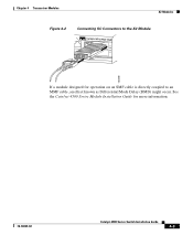
Chapter 4 Transceiver Modules X2 Modules Figure 4-2 Connecting SC Connectors to the X2 Module Catalyst WS-C4948 10GE X2-1 X2-2 CON MGT 130088 If a module designed for more information. 78-18039-02 Catalyst 4900 Series Switch Installation Guide 4-3 See the Catalyst 4500 Series Module Installation Guide for operation on an SMF cable is directly coupled to an MMF cable, an effect known as Differential Mode Delay (DMD) might occur.
Chapter 4 Transceiver Modules X2 Modules Figure 4-2 Connecting SC Connectors to the X2 Module Catalyst WS-C4948 10GE X2-1 X2-2 CON MGT 130088 If a module designed for more information. 78-18039-02 Catalyst 4900 Series Switch Installation Guide 4-3 See the Catalyst 4500 Series Module Installation Guide for operation on an SMF cable is directly coupled to an MMF cable, an effect known as Differential Mode Delay (DMD) might occur.

Installation Guide
Page 64
X2 Modules Chapter 4 Transceiver Modules Figure 4-3 Installing the 10-Gigabit Ethernet X2 Module Catalyst WS-C4948 10GE CON X1 MGT LINK X2 Catalyst WS-C4948 10GE CON X1 MGT X2 130091 Caution If you attempt to insert the bottom X2 module with the cooling fins pointing up, you will probably permanently damage the connector. Catalyst 4900 Series Switch Installation Guide 4-4 78-18039-02 For either the top or bottom connector, forcing a module could potentially damage both the module and the switch.
X2 Modules Chapter 4 Transceiver Modules Figure 4-3 Installing the 10-Gigabit Ethernet X2 Module Catalyst WS-C4948 10GE CON X1 MGT LINK X2 Catalyst WS-C4948 10GE CON X1 MGT X2 130091 Caution If you attempt to insert the bottom X2 module with the cooling fins pointing up, you will probably permanently damage the connector. Catalyst 4900 Series Switch Installation Guide 4-4 78-18039-02 For either the top or bottom connector, forcing a module could potentially damage both the module and the switch.

Installation Guide
Page 65
... to several microns in diameter, dust and any contamination at this URL: http://www.cisco.com/en/US/tech/tk482/tk876/technologies_white_paper09186a 0080254eba.shtml Module Maintenance Guidelines To properly maintain modules, follow these guidelines: • To prevent ESD damage, follow normal handling procedures. ... laser radiation may be absolutely free of trapped foreign material. 78-18039-02 Catalyst 4900 Series Switch Installation Guide 4-5 Chapter 4 Transceiver Modules Cleaning the Fiber-Optic Connectors Tip For complete information on the ferrules of the optical connectors.
... to several microns in diameter, dust and any contamination at this URL: http://www.cisco.com/en/US/tech/tk482/tk876/technologies_white_paper09186a 0080254eba.shtml Module Maintenance Guidelines To properly maintain modules, follow these guidelines: • To prevent ESD damage, follow normal handling procedures. ... laser radiation may be absolutely free of trapped foreign material. 78-18039-02 Catalyst 4900 Series Switch Installation Guide 4-5 Chapter 4 Transceiver Modules Cleaning the Fiber-Optic Connectors Tip For complete information on the ferrules of the optical connectors.

Installation Guide
Page 66
...tube around the fiber, and the end-face surface of a fiber-optic connector. Always clean fiber connectors before installing them. Statement 1051 Catalyst 4900 Series Switch Installation Guide 4-6 78-18039-02 Return loss is a significant, unexplained loss of light loss. As a general rule, whenever there ...Do not stare into beams or view directly with clean, dry, oil-free compressed air. Cleaning the Fiber-Optic Connectors Chapter 4 Transceiver Modules Connector loss, or insertion loss, is more common. Return loss specifies the amount of the fiber. Keep the connectors clean at all ...
...tube around the fiber, and the end-face surface of a fiber-optic connector. Always clean fiber connectors before installing them. Statement 1051 Catalyst 4900 Series Switch Installation Guide 4-6 78-18039-02 Return loss is a significant, unexplained loss of light loss. As a general rule, whenever there ...Do not stare into beams or view directly with clean, dry, oil-free compressed air. Cleaning the Fiber-Optic Connectors Chapter 4 Transceiver Modules Connector loss, or insertion loss, is more common. Return loss specifies the amount of the fiber. Keep the connectors clean at all ...

Installation Guide
Page 67
... the fiber-optic connectors in the proper manner. Repeat the process if any contamination is detected. Do not look directly into the aperture. Chapter 4 Transceiver Modules Cleaning the Fiber-Optic Connectors Step 3 Use a magnifying glass or inspection microscope to keep the inside of the system should be error free if the..., follows the previous directions, and follows these guidelines: • Clean the connectors using the connectors or while you are cleaning the chassis. 78-18039-02 Catalyst 4900 Series Switch Installation Guide 4-7
... the fiber-optic connectors in the proper manner. Repeat the process if any contamination is detected. Do not look directly into the aperture. Chapter 4 Transceiver Modules Cleaning the Fiber-Optic Connectors Step 3 Use a magnifying glass or inspection microscope to keep the inside of the system should be error free if the..., follows the previous directions, and follows these guidelines: • Clean the connectors using the connectors or while you are cleaning the chassis. 78-18039-02 Catalyst 4900 Series Switch Installation Guide 4-7

Installation Guide
Page 68
Cleaning the Fiber-Optic Connectors Chapter 4 Transceiver Modules Catalyst 4900 Series Switch Installation Guide 4-8 78-18039-02
Cleaning the Fiber-Optic Connectors Chapter 4 Transceiver Modules Catalyst 4900 Series Switch Installation Guide 4-8 78-18039-02

Installation Guide
Page 73
...the on /off switch is set correctly and... service representative for instructions. If no signal is detected, the LINK LED is off switch is set to a new power source, replace the power cord. If the LED ... source or the power cable. If the LED still fails to light when the switch is connected to another power source if one is probably faulty. If the LED ...lights, the problem is red, contact a customer service representative for instructions. 78-18039-02 Catalyst 4900 Series Switch Installation Guide 5-5 The port LED remains yellow if the port is operational (online). Chapter ...
...the on /off switch is set correctly and... service representative for instructions. If no signal is detected, the LINK LED is off switch is set to a new power source, replace the power cord. If the LED ... source or the power cable. If the LED still fails to light when the switch is connected to another power source if one is probably faulty. If the LED ...lights, the problem is red, contact a customer service representative for instructions. 78-18039-02 Catalyst 4900 Series Switch Installation Guide 5-5 The port LED remains yellow if the port is operational (online). Chapter ...