Installation Guide
Page 1
Catalyst 6500 Series Switches Installation Guide September 2010 Americas Headquarters Cisco Systems, Inc. 170 West Tasman Drive San Jose, CA 95134-1706 USA http://www.cisco.com Tel: 408 526-4000 800 553-NETS (6387) Fax: 408 527-0883 Text Part Number: OL-5781-08
Catalyst 6500 Series Switches Installation Guide September 2010 Americas Headquarters Cisco Systems, Inc. 170 West Tasman Drive San Jose, CA 95134-1706 USA http://www.cisco.com Tel: 408 526-4000 800 553-NETS (6387) Fax: 408 527-0883 Text Part Number: OL-5781-08

Installation Guide
Page 3
... ITS SUPPLIERS HAVE BEEN ADVISED OF THE POSSIBILITY OF SUCH DAMAGES. and other company. (1005R) Catalyst 6500 Series Switches Installation Guide Copyright © 1999-2010 Cisco Systems, Inc. CISCO AND THE ABOVE-NAMED SUPPLIERS DISCLAIM ALL WARRANTIES, EXPRESSED OR IMPLIED, INCLUDING, WITHOUT LIMITATION, THOSE OF MERCHANTABILITY, FITNESS FOR A PARTICULAR PURPOSE AND NONINFRINGEMENT OR ARISING...
... ITS SUPPLIERS HAVE BEEN ADVISED OF THE POSSIBILITY OF SUCH DAMAGES. and other company. (1005R) Catalyst 6500 Series Switches Installation Guide Copyright © 1999-2010 Cisco Systems, Inc. CISCO AND THE ABOVE-NAMED SUPPLIERS DISCLAIM ALL WARRANTIES, EXPRESSED OR IMPLIED, INCLUDING, WITHOUT LIMITATION, THOSE OF MERCHANTABILITY, FITNESS FOR A PARTICULAR PURPOSE AND NONINFRINGEMENT OR ARISING...
Installation Guide
Page 5
... Organization xi Conventions iii-xii Statement 1071-Warning Definition xiv Related Documentation xix Product Overview 1-1 Catalyst 6503 Switch 1-2 Catalyst 6503-E Switch 1-8 Catalyst 6504-E Switch 1-13 Catalyst 6506 Switch 1-18 Catalyst 6506-E Switch 1-24 Catalyst 6509 Switch 1-30 Catalyst 6509-E Switch 1-36 Catalyst 6509-NEB Switch 1-42 Catalyst 6509-NEB-A Switch 1-49 Catalyst 6509-V-E Switch 1-55 Catalyst 6513 Switch 1-61 Catalyst 6513-E Switch 1-67 Preparing for Installation 2-1 Safety 2-2 Site Requirements 2-2 Temperature 2-3 Air Flow 2-3 Humidity 2-14 Altitude 2-14...
... Organization xi Conventions iii-xii Statement 1071-Warning Definition xiv Related Documentation xix Product Overview 1-1 Catalyst 6503 Switch 1-2 Catalyst 6503-E Switch 1-8 Catalyst 6504-E Switch 1-13 Catalyst 6506 Switch 1-18 Catalyst 6506-E Switch 1-24 Catalyst 6509 Switch 1-30 Catalyst 6509-E Switch 1-36 Catalyst 6509-NEB Switch 1-42 Catalyst 6509-NEB-A Switch 1-49 Catalyst 6509-V-E Switch 1-55 Catalyst 6513 Switch 1-61 Catalyst 6513-E Switch 1-67 Preparing for Installation 2-1 Safety 2-2 Site Requirements 2-2 Temperature 2-3 Air Flow 2-3 Humidity 2-14 Altitude 2-14...

Installation Guide
Page 6
... DC-Powered Systems 2-23 Cabling Requirements 2-24 Site Preparation Checklist 2-24 Installing the Switch 3-1 Rack-Mounting Guidelines 3-3 Unpacking the Switch 3-5 Chassis Installation Kits and Cable Guides 3-5 Installing a Catalyst 6503 or Catalyst 6503-E Switch Chassis 3-8 Installation Accessory Kit 3-8 Rack-Mount Brackets on the Catalyst 6503 and the Catalyst 6503-E Switch Chassis 3-8 Rack-Mounting the Chassis 3-9 What is Next 3-11 Optional Installation Kits 3-11...
... DC-Powered Systems 2-23 Cabling Requirements 2-24 Site Preparation Checklist 2-24 Installing the Switch 3-1 Rack-Mounting Guidelines 3-3 Unpacking the Switch 3-5 Chassis Installation Kits and Cable Guides 3-5 Installing a Catalyst 6503 or Catalyst 6503-E Switch Chassis 3-8 Installation Accessory Kit 3-8 Rack-Mount Brackets on the Catalyst 6503 and the Catalyst 6503-E Switch Chassis 3-8 Rack-Mounting the Chassis 3-9 What is Next 3-11 Optional Installation Kits 3-11...
Installation Guide
Page 7
...25 Optional Installation Kits 3-25 Installing a Catalyst 6509-NEB or Catalyst 6509-NEB-A Switch Chassis 3-26 Installation Accessory Kits 3-26 L Brackets and the Optional Cable Guide on the Catalyst 6509-NEB Switch 3-26 L Brackets on the Catalyst 6509-NEB-A Switch Chassis 3-27 Installing the 3 RU Rack...(Optional) 3-40 What is Next 3-42 Optional Installation Kits 3-42 Installing a Catalyst 6513 or Catalyst 6513-E Switch Chassis 3-42 Installation Accessory Kit 3-42 L Brackets on the Catalyst 6513 and Catalyst 6513-E Switch Chassis 3-43 Installing the 3 RU Rack-Mount Shelf Kit 3-44 Rack-Mounting the...
...25 Optional Installation Kits 3-25 Installing a Catalyst 6509-NEB or Catalyst 6509-NEB-A Switch Chassis 3-26 Installation Accessory Kits 3-26 L Brackets and the Optional Cable Guide on the Catalyst 6509-NEB Switch 3-26 L Brackets on the Catalyst 6509-NEB-A Switch Chassis 3-27 Installing the 3 RU Rack...(Optional) 3-40 What is Next 3-42 Optional Installation Kits 3-42 Installing a Catalyst 6513 or Catalyst 6513-E Switch Chassis 3-42 Installation Accessory Kit 3-42 L Brackets on the Catalyst 6513 and Catalyst 6513-E Switch Chassis 3-43 Installing the 3 RU Rack-Mount Shelf Kit 3-44 Rack-Mounting the...
Installation Guide
Page 8
... Cables 3-61 Connecting the Supervisor Engine Console Port 3-61 Connecting the Supervisor Engine Uplink Ports 3-63 Using the Catalyst 6509-V-E Cable Management System 3-78 Verifying Switch Chassis Installation 3-84 Online Diagnostics 3-84 Removal and Replacement Procedures 4-1 Online Insertion and Removal 4-1 Removing and Installing... 4-83 Installing the Fan Assembly 4-92 Checking the Installation 4-92 Installing the Air Filter Assembly on a Catalyst 6509-NEB-A Switch or a Catalyst 6509-V-E (Optional) 4-93 Checking the Air Filter 4-98 Installing the Remote Power Cycling Feature Control Wires...
... Cables 3-61 Connecting the Supervisor Engine Console Port 3-61 Connecting the Supervisor Engine Uplink Ports 3-63 Using the Catalyst 6509-V-E Cable Management System 3-78 Verifying Switch Chassis Installation 3-84 Online Diagnostics 3-84 Removal and Replacement Procedures 4-1 Online Insertion and Removal 4-1 Removing and Installing... 4-83 Installing the Fan Assembly 4-92 Checking the Installation 4-92 Installing the Air Filter Assembly on a Catalyst 6509-NEB-A Switch or a Catalyst 6509-V-E (Optional) 4-93 Checking the Air Filter 4-98 Installing the Remote Power Cycling Feature Control Wires...
Installation Guide
Page 9
... A-60 8700 W Power Supply AC Power Cords A-62 AC Power Cord Illustrations A-63 Power Supply Redundancy A-73 Transceivers, Module Connectors, and Cable Specifications B-1 Pluggable Transceivers B-1 Catalyst 6500 Series Switches Installation Guide ix
... A-60 8700 W Power Supply AC Power Cords A-62 AC Power Cord Illustrations A-63 Power Supply Redundancy A-73 Transceivers, Module Connectors, and Cable Specifications B-1 Pluggable Transceivers B-1 Catalyst 6500 Series Switches Installation Guide ix

Installation Guide
Page 10
... Connector (WS-X6624-FXS Only) B-27 SC Connector B-28 MT-RJ Connector B-29 LC Connector B-30 Cables B-31 Console Port Mode Switch B-33 Identifying a Rollover Cable B-33 Console Port Mode 1 Signaling and Pinouts B-34 Console Port Mode 2 Signaling and Pinouts B-35 Mode...-Conditioning Patch Cord B-36 Cleaning the Fiber-Optic Connectors B-38 Repacking the Switch C-1 Chassis and Module Power and Heat Values D-1 Troubleshooting E-1 Getting Started E-1 Solving Problems at the System Component Level E-2 Identifying Startup Problems E-3...
... Connector (WS-X6624-FXS Only) B-27 SC Connector B-28 MT-RJ Connector B-29 LC Connector B-30 Cables B-31 Console Port Mode Switch B-33 Identifying a Rollover Cable B-33 Console Port Mode 1 Signaling and Pinouts B-34 Console Port Mode 2 Signaling and Pinouts B-35 Mode...-Conditioning Patch Cord B-36 Cleaning the Fiber-Optic Connectors B-38 Repacking the Switch C-1 Chassis and Module Power and Heat Values D-1 Troubleshooting E-1 Getting Started E-1 Solving Problems at the System Component Level E-2 Identifying Startup Problems E-3...
Installation Guide
Page 11
... for Installation Describes things you need to install your site before installing the Catalyst 6500 series switch. The chapter contains illustrations of the Catalyst 6500 series switches. Illustrations and specifications tables are provided for the supported AC power cords. Removal... and Provides procedures for the chassis. Installing the Switch Describes how to consider when preparing your Catalyst 6500 series switch. OL-5781-08 Catalyst 6500 Series Switches Installation Guide xi Organization This publication is organized, and its document ...
... for Installation Describes things you need to install your site before installing the Catalyst 6500 series switch. The chapter contains illustrations of the Catalyst 6500 series switches. Illustrations and specifications tables are provided for the supported AC power cords. Removal... and Provides procedures for the chassis. Installing the Switch Describes how to consider when preparing your Catalyst 6500 series switch. OL-5781-08 Catalyst 6500 Series Switches Installation Guide xi Organization This publication is organized, and its document ...
Installation Guide
Page 12
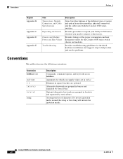
... the power consumption and heat dissipation values for the Catalyst 6500 series switch chassis and modules. Catalyst 6500 Series Switches Installation Guide xii OL-5781-08 Provides procedures to repack your Catalyst 6500 series switch if you supply values are grouped in brackets and separated... vertical bars. Provides listings of copper and optical transceiver modules, physical connectors, and the cables used with the Catalyst 6500 series switches. Provides troubleshooting guidelines for which you need to return it to help isolate and resolve problems. Conventions This publication...
... the power consumption and heat dissipation values for the Catalyst 6500 series switch chassis and modules. Catalyst 6500 Series Switches Installation Guide xii OL-5781-08 Provides procedures to repack your Catalyst 6500 series switch if you supply values are grouped in brackets and separated... vertical bars. Provides listings of copper and optical transceiver modules, physical connectors, and the cables used with the Catalyst 6500 series switches. Provides troubleshooting guidelines for which you need to return it to help isolate and resolve problems. Conventions This publication...
Installation Guide
Page 13
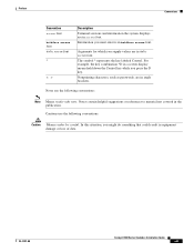
... enter is in screen font. Cautions use the following conventions: Caution Means reader be careful. The symbol ^ represents the key labeled Control. OL-5781-08 Catalyst 6500 Series Switches Installation Guide xiii Information you supply values are in the publication.
... enter is in screen font. Cautions use the following conventions: Caution Means reader be careful. The symbol ^ represents the key labeled Control. OL-5781-08 Catalyst 6500 Series Switches Installation Guide xiii Information you supply values are in the publication.
Installation Guide
Page 18
Conventions Preface xviii Catalyst 6500 Series Switches Installation Guide OL-5781-08
Conventions Preface xviii Catalyst 6500 Series Switches Installation Guide OL-5781-08

Installation Guide
Page 19
...; Regulatory Compliance and Safety Information for the Catalyst 6500 Series Switches • Catalyst 6500 Series Switch Quick Software Configuration Guide • Catalyst 6500 Series Switch Module Installation Guide • Catalyst 6500 Series Switch Software Configuration Guide • Catalyst 6500 Series Switch Command Reference • Catalyst 6500 Series Switch Cisco IOS Software Configuration Guide • Catalyst 6500 Series Switch Cisco IOS Command Reference • ATM Software Configuration...
...; Regulatory Compliance and Safety Information for the Catalyst 6500 Series Switches • Catalyst 6500 Series Switch Quick Software Configuration Guide • Catalyst 6500 Series Switch Module Installation Guide • Catalyst 6500 Series Switch Software Configuration Guide • Catalyst 6500 Series Switch Command Reference • Catalyst 6500 Series Switch Cisco IOS Software Configuration Guide • Catalyst 6500 Series Switch Cisco IOS Command Reference • ATM Software Configuration...

Installation Guide
Page 20
Catalyst 6500 Series Switches Installation Guide xx OL-5781-08 Related Documentation Preface Obtaining Documentation and Submitting a Service Request For information on obtaining documentation, submitting a service request, and gathering additional information, see the monthly What's New in Cisco Product Documentation, which also lists all new and revised Cisco technical documentation, at: http://www.cisco.com/en...
Catalyst 6500 Series Switches Installation Guide xx OL-5781-08 Related Documentation Preface Obtaining Documentation and Submitting a Service Request For information on obtaining documentation, submitting a service request, and gathering additional information, see the monthly What's New in Cisco Product Documentation, which also lists all new and revised Cisco technical documentation, at: http://www.cisco.com/en...
Installation Guide
Page 21
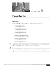
...; Catalyst 6503 Switch, page 1-2 • Catalyst 6503-E Switch, page 1-8 • Catalyst 6504-E Switch, page 1-13 • Catalyst 6506 Switch, page 1-18 • Catalyst 6506-E Switch, page 1-24 • Catalyst 6509 Switch, page 1-30 • Catalyst 6509-E Switch, page 1-36 • Catalyst 6509-NEB Switch, page 1-42 • Catalyst 6509-NEB-A Switch, page 1-49 • Catalyst 6509-V-E Switch, page 1-55 • Catalyst 6513 Switch, page 1-61 • Catalyst 6513-E Switch, page 1-67 Note The Catalyst 6000 series switches (Catalyst 6006 switch...
...; Catalyst 6503 Switch, page 1-2 • Catalyst 6503-E Switch, page 1-8 • Catalyst 6504-E Switch, page 1-13 • Catalyst 6506 Switch, page 1-18 • Catalyst 6506-E Switch, page 1-24 • Catalyst 6509 Switch, page 1-30 • Catalyst 6509-E Switch, page 1-36 • Catalyst 6509-NEB Switch, page 1-42 • Catalyst 6509-NEB-A Switch, page 1-49 • Catalyst 6509-V-E Switch, page 1-55 • Catalyst 6513 Switch, page 1-61 • Catalyst 6513-E Switch, page 1-67 Note The Catalyst 6000 series switches (Catalyst 6006 switch...
Installation Guide
Page 22
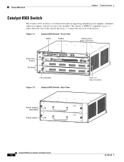
... chassis supporting redundant power supplies, redundant supervisor engines, and slots for up to bottom) Figure 1-2 Catalyst 6503 Switch-Rear View 63031 Power supply 2 (redundant) Power supply 1 INPUT FAN OUTPUT OK OK FAIL INPUT FAN OUTPUT OK OK FAIL Catalyst 6500 Series Switches Installation Guide 1-2 OL-5781-08 Catalyst 6503 Switch Chapter 1 Product Overview Catalyst 6503 Switch The Catalyst 6503 switch is NEBS L3 compliant.
... chassis supporting redundant power supplies, redundant supervisor engines, and slots for up to bottom) Figure 1-2 Catalyst 6503 Switch-Rear View 63031 Power supply 2 (redundant) Power supply 1 INPUT FAN OUTPUT OK OK FAIL INPUT FAN OUTPUT OK OK FAIL Catalyst 6500 Series Switches Installation Guide 1-2 OL-5781-08 Catalyst 6503 Switch Chapter 1 Product Overview Catalyst 6503 Switch The Catalyst 6503 switch is NEBS L3 compliant.

Installation Guide
Page 23
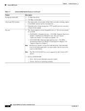
...for any restrictions on the type of the Catalyst 6503 switch chassis. Chapter 1 Product Overview Catalyst 6503 Switch Table 1-1 lists the features of module that the optional high-speed fan tray (FAN-MOD-3HS) be installed. Table 1-1 Catalyst 6503 Switch Features Feature Chassis Supervisor engine Description •... notes for specific information. Modules • Supervisor Engine 720 with the smaller memory configuration is not supported on the Catalyst 6503 switch chassis. • Supervisor Engine 32, Supervisor Engine 32 PISA, or a Supervisor Engine 720 requires that can be ...
...for any restrictions on the type of the Catalyst 6503 switch chassis. Chapter 1 Product Overview Catalyst 6503 Switch Table 1-1 lists the features of module that the optional high-speed fan tray (FAN-MOD-3HS) be installed. Table 1-1 Catalyst 6503 Switch Features Feature Chassis Supervisor engine Description •... notes for specific information. Modules • Supervisor Engine 720 with the smaller memory configuration is not supported on the Catalyst 6503 switch chassis. • Supervisor Engine 32, Supervisor Engine 32 PISA, or a Supervisor Engine 720 requires that can be ...
Installation Guide
Page 24
... signals. • The chassis supports one hot-swappable fan tray. Two fan tray models are not field replaceable; Supports Supervisor Engine 1 and Supervisor Engine 2 only; Catalyst 6503 Switch Chapter 1 Product Overview Table 1-1 Catalyst 6503 Switch Features (continued) Feature Backplane bandwidth Clock and VTT modules Fan tray Description • 32 GBps shared bus. • 720 GBps...
... signals. • The chassis supports one hot-swappable fan tray. Two fan tray models are not field replaceable; Supports Supervisor Engine 1 and Supervisor Engine 2 only; Catalyst 6503 Switch Chapter 1 Product Overview Table 1-1 Catalyst 6503 Switch Features (continued) Feature Backplane bandwidth Clock and VTT modules Fan tray Description • 32 GBps shared bus. • 720 GBps...
Installation Guide
Page 25
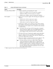
The second power supply is required for Catalyst 6503 and Catalyst 6503-E switches only. OL-5781-08 Catalyst 6500 Series Switches Installation Guide 1-5 PEM-DC/3 (PEM for 950 W AC-input power supplies). - PWR-950-DC (950 W DC-...installed power supply. - Failure to meet these chassis do not have a minimum configuration of different wattage ratings. Chapter 1 Product Overview Catalyst 6503 Switch Table 1-1 Catalyst 6503 Switch Features (continued) Feature Power Entry Module (PEM)1 Power supplies Description • A PEM is installed in the upper power supply bay...
The second power supply is required for Catalyst 6503 and Catalyst 6503-E switches only. OL-5781-08 Catalyst 6500 Series Switches Installation Guide 1-5 PEM-DC/3 (PEM for 950 W AC-input power supplies). - PWR-950-DC (950 W DC-...installed power supply. - Failure to meet these chassis do not have a minimum configuration of different wattage ratings. Chapter 1 Product Overview Catalyst 6503 Switch Table 1-1 Catalyst 6503 Switch Features (continued) Feature Power Entry Module (PEM)1 Power supplies Description • A PEM is installed in the upper power supply bay...
Installation Guide
Page 26
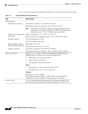
... Bystander position operating to an ambient temperature of the Catalyst 6503 switch chassis. Catalyst 6503 Switch Chapter 1 Product Overview Table 1-2 lists the environmental and physical specifications of 86°F (30°C). Table 1-2 Catalyst 6503 Switch Specifications Item Environmental Temperature, operating Temperature, nonoperating and ... Designed and tested for operation: 32° to 131°F (0° to 55°C) Note The Catalyst 6500 series switches are equipped with Network Equipment Building Systems (NEBS) (Zone 4 per GR-63-Core) in protective shipping package...
... Bystander position operating to an ambient temperature of the Catalyst 6503 switch chassis. Catalyst 6503 Switch Chapter 1 Product Overview Table 1-2 lists the environmental and physical specifications of 86°F (30°C). Table 1-2 Catalyst 6503 Switch Specifications Item Environmental Temperature, operating Temperature, nonoperating and ... Designed and tested for operation: 32° to 131°F (0° to 55°C) Note The Catalyst 6500 series switches are equipped with Network Equipment Building Systems (NEBS) (Zone 4 per GR-63-Core) in protective shipping package...
