
Installation Guide
Page 2
... at your equipment is causing interference by Cisco Systems, Inc. The Cisco implementation of TCP header compression is an adaptation of a program developed by the Cisco equipment or one side or the other of the FCC rules. These specifications are designed to part 15 of the ... ARE UNABLE TO LOCATE THE SOFTWARE LICENSE OR LIMITED WARRANTY, CONTACT YOUR CISCO REPRESENTATIVE FOR A COPY. All rights reserved. However, there is for a Class B digital device in accordance with the specifications in accordance with the instruction manual, may be required to radio or television...
... at your equipment is causing interference by Cisco Systems, Inc. The Cisco implementation of TCP header compression is an adaptation of a program developed by the Cisco equipment or one side or the other of the FCC rules. These specifications are designed to part 15 of the ... ARE UNABLE TO LOCATE THE SOFTWARE LICENSE OR LIMITED WARRANTY, CONTACT YOUR CISCO REPRESENTATIVE FOR A COPY. All rights reserved. However, there is for a Class B digital device in accordance with the specifications in accordance with the instruction manual, may be required to radio or television...
Installation Guide
Page 9
...W AC-Input and DC-Input Power Supplies A-46 6000 W Power Supply Specifications A-48 6000 W Power Supply AC Power Cords A-53 8700 W AC-Input Power Supply A-54 8700 W Power Supply Specifications A-55 Remote Power Cycling Feature A-60 8700 W Power Supply AC Power ...Cords A-62 AC Power Cord Illustrations A-63 Power Supply Redundancy A-73 Transceivers, Module Connectors, and Cable Specifications B-1 Pluggable Transceivers B-1 Catalyst 6500 Series Switches Installation Guide ix
...W AC-Input and DC-Input Power Supplies A-46 6000 W Power Supply Specifications A-48 6000 W Power Supply AC Power Cords A-53 8700 W AC-Input Power Supply A-54 8700 W Power Supply Specifications A-55 Remote Power Cycling Feature A-60 8700 W Power Supply AC Power ...Cords A-62 AC Power Cord Illustrations A-63 Power Supply Redundancy A-73 Transceivers, Module Connectors, and Cable Specifications B-1 Pluggable Transceivers B-1 Catalyst 6500 Series Switches Installation Guide ix
Installation Guide
Page 11
...brackets installed, and freestanding with rubber feet installed. Power Supply Specifications Provides illustrations and specification tables for removing and installing chassis Replacement Procedures components. OL-5781-08 Catalyst 6500 Series Switches Installation Guide xi Installing the Switch Describes how... described in this publication. Removal and Provides procedures for the available Catalyst 6500 series switch AC-input and DC-input power supplies. Illustrations and specifications tables are provided for Installation Describes things you need to install your...
...brackets installed, and freestanding with rubber feet installed. Power Supply Specifications Provides illustrations and specification tables for removing and installing chassis Replacement Procedures components. OL-5781-08 Catalyst 6500 Series Switches Installation Guide xi Installing the Switch Describes how... described in this publication. Removal and Provides procedures for the available Catalyst 6500 series switch AC-input and DC-input power supplies. Illustrations and specifications tables are provided for Installation Describes things you need to install your...
Installation Guide
Page 12
...by vertical bars. A nonquoted set of copper and optical transceiver modules, physical connectors, and the cables used with the Catalyst 6500 series switches. Do not use quotation marks around the string or the string will include the quotation marks. Arguments ...Catalyst 6500 series switch chassis and modules. Provides listings of the power consumption and heat dissipation values for the initial hardware installation and suggests steps to the factory. Conventions Preface Chapter Appendix B Appendix C Appendix D Appendix E Title Transceivers, Module Connectors, and Cable Specifications...
...by vertical bars. A nonquoted set of copper and optical transceiver modules, physical connectors, and the cables used with the Catalyst 6500 series switches. Do not use quotation marks around the string or the string will include the quotation marks. Arguments ...Catalyst 6500 series switch chassis and modules. Provides listings of the power consumption and heat dissipation values for the initial hardware installation and suggests steps to the factory. Conventions Preface Chapter Appendix B Appendix C Appendix D Appendix E Title Transceivers, Module Connectors, and Cable Specifications...

Installation Guide
Page 23
... be used for any restrictions on the type of the Catalyst 6503 switch chassis. Each supervisor engine must have the resources to support the supervisor engines. • Supervisor engines can be installed. Have chassis slot restrictions - Require a specific software release level to two Catalyst 6500 series modules. • Does not support the WS-C6500...
... be used for any restrictions on the type of the Catalyst 6503 switch chassis. Each supervisor engine must have the resources to support the supervisor engines. • Supervisor engines can be installed. Have chassis slot restrictions - Require a specific software release level to two Catalyst 6500 series modules. • Does not support the WS-C6500...
Installation Guide
Page 26
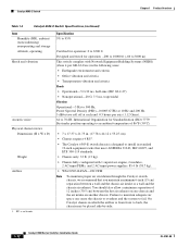
... 86°F (30°C). International Organization for Standardization (ISO) 7779: Bystander position operating to an ambient temperature of the Catalyst 6503 switch chassis. Catalyst 6500 Series Switches Installation Guide 1-6 OL-5781-08 Table 1-2 Catalyst 6503 Switch Specifications Item Environmental Temperature, operating Temperature, nonoperating and storage Thermal transition Humidity (RH), ambient (noncondensing) operating Altitude, operating Shock and...
... 86°F (30°C). International Organization for Standardization (ISO) 7779: Bystander position operating to an ambient temperature of the Catalyst 6503 switch chassis. Catalyst 6500 Series Switches Installation Guide 1-6 OL-5781-08 Table 1-2 Catalyst 6503 Switch Specifications Item Environmental Temperature, operating Temperature, nonoperating and storage Thermal transition Humidity (RH), ambient (noncondensing) operating Altitude, operating Shock and...
Installation Guide
Page 27
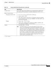
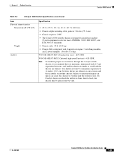
... chassis to overheat and the system to back, the chassis may be placed side-by-side. Chapter 1 Product Overview Catalyst 6503 Switch Table 1-2 Catalyst 6503 Switch Specifications (continued) Item Physical Characteristics Dimensions (H x W x D) Weight Airflow 1. RU = rack units Specification • 7 x 17.37 x 21.75 in standard 19-inch equipment racks that meet ANSI/EIA 310-D, IEC 60297...
... chassis to overheat and the system to back, the chassis may be placed side-by-side. Chapter 1 Product Overview Catalyst 6503 Switch Table 1-2 Catalyst 6503 Switch Specifications (continued) Item Physical Characteristics Dimensions (H x W x D) Weight Airflow 1. RU = rack units Specification • 7 x 17.37 x 21.75 in standard 19-inch equipment racks that meet ANSI/EIA 310-D, IEC 60297...
Installation Guide
Page 29
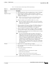
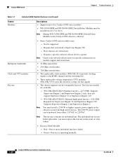
... slot restrictions - Identical supervisor engine memory configurations are recommended, but are duplicated. OL-5781-08 Catalyst 6500 Series Switches Installation Guide 1-9 Table 1-3 Catalyst 6503-E Switch Features Feature Chassis Supervisor engine Description • Three horizontal slots. Check your software release notes...when it is sufficient to support the supervisor engines. • Supervisor engines can be installed. Require a specific software release level to two Catalyst 6500 series modules. • Does not support the WS-C6500-SFM and WS-X6500-SFM2 Switch Fabric...
... slot restrictions - Identical supervisor engine memory configurations are recommended, but are duplicated. OL-5781-08 Catalyst 6500 Series Switches Installation Guide 1-9 Table 1-3 Catalyst 6503-E Switch Features Feature Chassis Supervisor engine Description • Three horizontal slots. Check your software release notes...when it is sufficient to support the supervisor engines. • Supervisor engines can be installed. Require a specific software release level to two Catalyst 6500 series modules. • Does not support the WS-C6500-SFM and WS-X6500-SFM2 Switch Fabric...
Installation Guide
Page 31
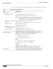
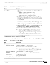
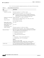
... alarm. PWR-950-AC (950 W AC-input power supply). - Table 1-4 Catalyst 6503-E Switch Specifications Item Environmental Temperature, operating Temperature, nonoperating and storage Thermal transition Humidity (RH), ambient (noncondensing) operating Specification Certified for operation: 32° to 104°F (0° to 90% OL...per minute (hot to cold) 0.33°C per minute (cold to hot) 5% to 40°C) Designed and tested for Catalyst 6503 and Catalyst 6503-E switches only. Failure to operate. Chassis unpackaged: -4° to 149°F (-20° to 65°C) Chassis in...
... alarm. PWR-950-AC (950 W AC-input power supply). - Table 1-4 Catalyst 6503-E Switch Specifications Item Environmental Temperature, operating Temperature, nonoperating and storage Thermal transition Humidity (RH), ambient (noncondensing) operating Specification Certified for operation: 32° to 104°F (0° to 90% OL...per minute (hot to cold) 0.33°C per minute (cold to hot) 5% to 40°C) Designed and tested for Catalyst 6503 and Catalyst 6503-E switches only. Failure to operate. Chassis unpackaged: -4° to 149°F (-20° to 65°C) Chassis in...
Installation Guide
Page 32
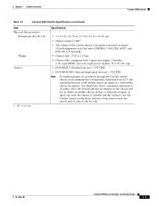
... the chassis to overheat and the system to back, the chassis may be placed side-by-side. 1-12 Catalyst 6500 Series Switches Installation Guide OL-5781-08 Catalyst 6503-E Switch Chapter 1 Product Overview Table 1-4 Catalyst 6503-E Switch Specifications (continued) Item Humidity (RH), ambient (noncondensing) nonoperating and storage Altitude, operating Shock and vibration Acoustic noise Physical characteristics...
... the chassis to overheat and the system to back, the chassis may be placed side-by-side. 1-12 Catalyst 6500 Series Switches Installation Guide OL-5781-08 Catalyst 6503-E Switch Chapter 1 Product Overview Table 1-4 Catalyst 6503-E Switch Specifications (continued) Item Humidity (RH), ambient (noncondensing) nonoperating and storage Altitude, operating Shock and vibration Acoustic noise Physical characteristics...

Installation Guide
Page 34
... as the supervisor engine with redundant supervisor engines, both supervisor engines must be used for specific information. • 32 GBps shared bus. • 720 GBps switch fabric. 1-14 Catalyst 6500 Series Switches Installation Guide OL-5781-08 Catalyst 6504-E Switch Chapter 1 Product Overview Table 1-5 lists the features of the switch. Slots are duplicated...
... as the supervisor engine with redundant supervisor engines, both supervisor engines must be used for specific information. • 32 GBps shared bus. • 720 GBps switch fabric. 1-14 Catalyst 6500 Series Switches Installation Guide OL-5781-08 Catalyst 6504-E Switch Chapter 1 Product Overview Table 1-5 lists the features of the switch. Slots are duplicated...

Installation Guide
Page 36
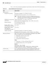
... 2000 m) Designed and tested for operation: 32° to 131°F (0° to 500 Hz. Catalyst 6504-E Switch Chapter 1 Product Overview Table 1-6 lists the environmental and physical specifications of the Catalyst 6504-E switch chassis. Table 1-6 Catalyst 6504-E Switch Specifications Item Environmental Temperature, operating Temperature, nonoperating and storage Thermal transition Humidity (RH), ambient (noncondensing) operating Humidity...
... 2000 m) Designed and tested for operation: 32° to 131°F (0° to 500 Hz. Catalyst 6504-E Switch Chapter 1 Product Overview Table 1-6 lists the environmental and physical specifications of the Catalyst 6504-E switch chassis. Table 1-6 Catalyst 6504-E Switch Specifications Item Environmental Temperature, operating Temperature, nonoperating and storage Thermal transition Humidity (RH), ambient (noncondensing) operating Humidity...
Installation Guide
Page 37
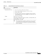
...(30°C). • 8.7 x 17.5 x 21.6 in. (22.09 x 44.45 x 54.86 cm). • Chassis requires 5 RU1. • The Catalyst 6504-E switch chassis is from front to install in which the airflow is designed to back, the chassis may be placed side-by-side. Failure... air circulation through the Catalyst switch chassis, we recommend that you maintain a minimum 6-inch (15 cm) separation between the hot air exhaust on one chassis and the air intake on another chassis. Chapter 1 Product Overview Catalyst 6504-E Switch Table 1-6 Catalyst 6504-E Switch Specifications (continued) Item Acoustic...
...(30°C). • 8.7 x 17.5 x 21.6 in. (22.09 x 44.45 x 54.86 cm). • Chassis requires 5 RU1. • The Catalyst 6504-E switch chassis is from front to install in which the airflow is designed to back, the chassis may be placed side-by-side. Failure... air circulation through the Catalyst switch chassis, we recommend that you maintain a minimum 6-inch (15 cm) separation between the hot air exhaust on one chassis and the air intake on another chassis. Chapter 1 Product Overview Catalyst 6504-E Switch Table 1-6 Catalyst 6504-E Switch Specifications (continued) Item Acoustic...
Installation Guide
Page 40
...that you must install a 2500 W or higher capacity power supply in slot 5 or slot 6. Require a specific software release level to operate Note Check your software release notes for specific information on module support and restrictions. • 32 GBps shared bus. • 256 GBps switch fabric. ...• 720 GBps switch fabric. • Two replaceable clock modules (WS-C6K-CL=) provide clocking signals to five Catalyst 6500 series modules. •...
...that you must install a 2500 W or higher capacity power supply in slot 5 or slot 6. Require a specific software release level to operate Note Check your software release notes for specific information on module support and restrictions. • 32 GBps shared bus. • 256 GBps switch fabric. ...• 720 GBps switch fabric. • Two replaceable clock modules (WS-C6K-CL=) provide clocking signals to five Catalyst 6500 series modules. •...
Installation Guide
Page 42
... Density (PSD)-0.0005 G2/Hz at 10 Hz and 200 Hz. 5 dB/octave roll off at 131°F (55°C) generating a major alarm. Table 1-8 Catalyst 6506 Switch Specifications Item Environmental Temperature, operating Temperature, nonoperating and storage Thermal transition Humidity (RH), ambient (noncondensing) operating Humidity (RH), ambient (noncondensing) nonoperating and storage Altitude, operating...
... Density (PSD)-0.0005 G2/Hz at 10 Hz and 200 Hz. 5 dB/octave roll off at 131°F (55°C) generating a major alarm. Table 1-8 Catalyst 6506 Switch Specifications Item Environmental Temperature, operating Temperature, nonoperating and storage Thermal transition Humidity (RH), ambient (noncondensing) operating Humidity (RH), ambient (noncondensing) nonoperating and storage Altitude, operating...
Installation Guide
Page 43
... is designed to install in . (55.0 cm). • Chassis requires 12 RU. • The Catalyst 6506 switch chassis is from front to fail. Chapter 1 Product Overview Catalyst 6506 Switch Table 1-8 Catalyst 6506 Switch Specifications (continued) Item Physical characteristics Dimensions (H x W x D) Weight Airflow Specification • 20.1 x 17.2 x 18.1 in. (51.1 x 43.7 x 46.0 cm). • Chassis depth including...
... is designed to install in . (55.0 cm). • Chassis requires 12 RU. • The Catalyst 6506 switch chassis is from front to fail. Chapter 1 Product Overview Catalyst 6506 Switch Table 1-8 Catalyst 6506 Switch Specifications (continued) Item Physical characteristics Dimensions (H x W x D) Weight Airflow Specification • 20.1 x 17.2 x 18.1 in. (51.1 x 43.7 x 46.0 cm). • Chassis depth including...

Installation Guide
Page 46
... a fan failure. • Fan tray STATUS LED - Backplane bandwidth Clock and VTT modules Fan tray • Some Catalyst 6500 series modules may: - Require a specific software release level to operate Note Check your software release notes for bus signals. • The chassis supports one hot-... to the EOBC channel and the switching bus. • Three replaceable voltage termination (VTT) modules (WS-C6K-VTT-E=) provide reference voltage for specific information on module support and restrictions. • 32 GBps shared bus. • 256 GBps switch fabric. • 720 GBps switch fabric....
... a fan failure. • Fan tray STATUS LED - Backplane bandwidth Clock and VTT modules Fan tray • Some Catalyst 6500 series modules may: - Require a specific software release level to operate Note Check your software release notes for bus signals. • The chassis supports one hot-... to the EOBC channel and the switching bus. • Three replaceable voltage termination (VTT) modules (WS-C6K-VTT-E=) provide reference voltage for specific information on module support and restrictions. • 32 GBps shared bus. • 256 GBps switch fabric. • 720 GBps switch fabric....
Installation Guide
Page 48
... 131°F (55°C) generating a major alarm. Catalyst 6506-E Switch Chapter 1 Product Overview Table 1-10 lists the environmental and physical specifications of 86°F (30°C). 1-28 Catalyst 6500 Series Switches Installation Guide OL-5781-08 International Organization... for Standardization (ISO) 7779: Bystander position operating to 61 dB. Table 1-10 Catalyst 6506-E Switch Specifications Item Environmental Temperature, operating Temperature, nonoperating and storage Thermal transition Humidity (RH), ambient (noncondensing) operating ...
... 131°F (55°C) generating a major alarm. Catalyst 6506-E Switch Chapter 1 Product Overview Table 1-10 lists the environmental and physical specifications of 86°F (30°C). 1-28 Catalyst 6500 Series Switches Installation Guide OL-5781-08 International Organization... for Standardization (ISO) 7779: Bystander position operating to 61 dB. Table 1-10 Catalyst 6506-E Switch Specifications Item Environmental Temperature, operating Temperature, nonoperating and storage Thermal transition Humidity (RH), ambient (noncondensing) operating ...
Installation Guide
Page 49
... 1 supervisor engine, 5 switching modules, and 2 power supplies: 159 lb (72.3 kg). WS-C6506-E-FAN-564 CFM. Chapter 1 Product Overview Catalyst 6506-E Switch Table 1-10 Catalyst 6506-E Switch Specifications (continued) Item Physical characteristics Dimensions (H x W x D) Weight Airflow Specification • 19.2 x 17.5 x 18.2 in. (48.8 x 44.5 x 46.0 cm). • Chassis depth including cable guide is 21.64...
... 1 supervisor engine, 5 switching modules, and 2 power supplies: 159 lb (72.3 kg). WS-C6506-E-FAN-564 CFM. Chapter 1 Product Overview Catalyst 6506-E Switch Table 1-10 Catalyst 6506-E Switch Specifications (continued) Item Physical characteristics Dimensions (H x W x D) Weight Airflow Specification • 19.2 x 17.5 x 18.2 in. (48.8 x 44.5 x 46.0 cm). • Chassis depth including cable guide is 21.64...

Installation Guide
Page 52
Backplane bandwidth Clock and VTT modules Fan tray • Some Catalyst 6500 series modules may: - Require a specific software release level to operate Note Check your software release notes for specific information on modules supported and restrictions. • 32 GBps shared bus. • 256 GBps ... STATUS LED - Note The fan tray contains nine individual fans. Catalyst 6509 Switch Chapter 1 Product Overview Table 1-11 Catalyst 6509 Switch Features (continued) Feature Modules Description • Supports up to eight Catalyst 6500 series modules. • WS-C6500-SFM and WS-X6500-SFM2...
Backplane bandwidth Clock and VTT modules Fan tray • Some Catalyst 6500 series modules may: - Require a specific software release level to operate Note Check your software release notes for specific information on modules supported and restrictions. • 32 GBps shared bus. • 256 GBps ... STATUS LED - Note The fan tray contains nine individual fans. Catalyst 6509 Switch Chapter 1 Product Overview Table 1-11 Catalyst 6509 Switch Features (continued) Feature Modules Description • Supports up to eight Catalyst 6500 series modules. • WS-C6500-SFM and WS-X6500-SFM2...