Installation Guide
Page 9
...-Input and DC-Input Power Supplies A-46 6000 W Power Supply Specifications A-48 6000 W Power Supply AC Power Cords A-53 8700 W AC-Input Power Supply A-54 8700 W Power Supply Specifications A-55 Remote Power Cycling Feature A-60 8700 W Power Supply AC Power Cords A-62 AC Power Cord Illustrations A-63 Power Supply Redundancy A-73 Transceivers, Module Connectors, and Cable Specifications B-1 Pluggable Transceivers B-1 Catalyst 6500 Series Switches...
...-Input and DC-Input Power Supplies A-46 6000 W Power Supply Specifications A-48 6000 W Power Supply AC Power Cords A-53 8700 W AC-Input Power Supply A-54 8700 W Power Supply Specifications A-55 Remote Power Cycling Feature A-60 8700 W Power Supply AC Power Cords A-62 AC Power Cord Illustrations A-63 Power Supply Redundancy A-73 Transceivers, Module Connectors, and Cable Specifications B-1 Pluggable Transceivers B-1 Catalyst 6500 Series Switches...

Installation Guide
Page 10
... Cord B-36 Cleaning the Fiber-Optic Connectors B-38 Repacking the Switch C-1 Chassis and Module Power and Heat Values D-1 Troubleshooting E-1 Getting Started E-1 Solving Problems at the System Component Level E-2 Identifying Startup Problems E-3 Troubleshooting the Power Supply E-4 Troubleshooting the Fan Assembly E-5 Troubleshooting Modules E-5 STATUS LED Indications E-5 Contacting Customer Service E-7 Catalyst 6500 Series Switches Installation Guide x OL...
... Cord B-36 Cleaning the Fiber-Optic Connectors B-38 Repacking the Switch C-1 Chassis and Module Power and Heat Values D-1 Troubleshooting E-1 Getting Started E-1 Solving Problems at the System Component Level E-2 Identifying Startup Problems E-3 Troubleshooting the Power Supply E-4 Troubleshooting the Fan Assembly E-5 Troubleshooting Modules E-5 STATUS LED Indications E-5 Contacting Customer Service E-7 Catalyst 6500 Series Switches Installation Guide x OL...
Installation Guide
Page 12
...bars. Conventions Preface Chapter Appendix B Appendix C Appendix D Appendix E Title Transceivers, Module Connectors, and Cable Specifications Repacking the Switch Chassis and Module Power and Heat Values Troubleshooting Description Gives brief descriptions of the different types of characters. Provides ...nonquoted set of copper and optical transceiver modules, physical connectors, and the cables used with the Catalyst 6500 series switches. Provides listings of the power consumption and heat dissipation values for the Catalyst 6500 series switch chassis and modules. Elements in italics...
...bars. Conventions Preface Chapter Appendix B Appendix C Appendix D Appendix E Title Transceivers, Module Connectors, and Cable Specifications Repacking the Switch Chassis and Module Power and Heat Values Troubleshooting Description Gives brief descriptions of the different types of characters. Provides ...nonquoted set of copper and optical transceiver modules, physical connectors, and the cables used with the Catalyst 6500 series switches. Provides listings of the power consumption and heat dissipation values for the Catalyst 6500 series switch chassis and modules. Elements in italics...

Installation Guide
Page 38
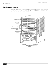
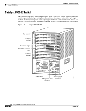
... 2.0 USB 2.0 LINK o o INPUT OK FAN OUTPUT OK FAIL INPUT OK FAN OUTPUT OK FAIL Power supply 1 Power supply 2 ESD ground strap (redundant) connector 18224 1-18 Catalyst 6500 Series Switches Installation Guide OL-5781-08 Catalyst 6506 Switch Chapter 1 Product Overview Catalyst 6506 Switch The Catalyst 6506 switch is NEBS L3 compliant. Figure 1-7 shows a front view of the...
... 2.0 USB 2.0 LINK o o INPUT OK FAN OUTPUT OK FAIL INPUT OK FAN OUTPUT OK FAIL Power supply 1 Power supply 2 ESD ground strap (redundant) connector 18224 1-18 Catalyst 6500 Series Switches Installation Guide OL-5781-08 Catalyst 6506 Switch Chapter 1 Product Overview Catalyst 6506 Switch The Catalyst 6506 switch is NEBS L3 compliant. Figure 1-7 shows a front view of the...

Installation Guide
Page 44
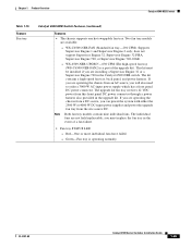
... OK FAN OUTPUT OK FAIL INPUT OK FAN OUTPUT OK FAIL Power supply 1 Power supply 2 ESD ground strap (redundant) connector Table 1-9 lists the features of the Catalyst 6506 switch. The Catalyst 6506-E switch chassis is an enhanced version of the Catalyst 6506-E switch chassis. 18224 1-24 Catalyst 6500 Series Switches Installation Guide OL-5781-08 Figure 1-8 shows...
... OK FAN OUTPUT OK FAIL INPUT OK FAN OUTPUT OK FAIL Power supply 1 Power supply 2 ESD ground strap (redundant) connector Table 1-9 lists the features of the Catalyst 6506 switch. The Catalyst 6506-E switch chassis is an enhanced version of the Catalyst 6506-E switch chassis. 18224 1-24 Catalyst 6500 Series Switches Installation Guide OL-5781-08 Figure 1-8 shows...
Installation Guide
Page 50
... LINK LINK LINK LINK LINK LINK LINK LINK LINK LINK LINK LINK LINK o o INPUT OK FAN OUTPUT OK FAIL INPUT OK FAN OUTPUT OK FAIL Power supply 1 Power supply 2 ESD ground strap (redundant) connector 16076 1-30 Catalyst 6500 Series Switches Installation Guide OL-5781-08 The chassis is a 9-slot horizontal chassis supporting redundant...
... LINK LINK LINK LINK LINK LINK LINK LINK LINK LINK LINK LINK LINK o o INPUT OK FAN OUTPUT OK FAIL INPUT OK FAN OUTPUT OK FAIL Power supply 1 Power supply 2 ESD ground strap (redundant) connector 16076 1-30 Catalyst 6500 Series Switches Installation Guide OL-5781-08 The chassis is a 9-slot horizontal chassis supporting redundant...
Installation Guide
Page 56
...enhanced version of the Catalyst 6509 switch. Figure 1-10 shows the Catalyst 6509-E switch. Catalyst 6509-E Switch Chapter 1 Product Overview Catalyst 6509-E Switch The Catalyst 6509-E switch is NEBS L3 compliant. It also supports a greater power capacity per slot than the Catalyst 6509 switch chassis. Figure 1-10 Catalyst 6509-E Switch Fan... 22 LINK 23 LINK 24 LINK o o INPUT OK FAN OUTPUT OK FAIL INPUT OK FAN OUTPUT OK FAIL Power supply 1 Power supply 2 ESD ground strap (redundant) connector 113676 1-36 Catalyst 6500 Series Switches Installation Guide OL-5781-08
...enhanced version of the Catalyst 6509 switch. Figure 1-10 shows the Catalyst 6509-E switch. Catalyst 6509-E Switch Chapter 1 Product Overview Catalyst 6509-E Switch The Catalyst 6509-E switch is NEBS L3 compliant. It also supports a greater power capacity per slot than the Catalyst 6509 switch chassis. Figure 1-10 Catalyst 6509-E Switch Fan... 22 LINK 23 LINK 24 LINK o o INPUT OK FAN OUTPUT OK FAIL INPUT OK FAN OUTPUT OK FAIL Power supply 1 Power supply 2 ESD ground strap (redundant) connector 113676 1-36 Catalyst 6500 Series Switches Installation Guide OL-5781-08
Installation Guide
Page 65
...contains a high-speed fan tray, back panel, and power harness. If you can power the system with either the 2500 W or 4000 W DC-input power supplies and power the upgrade fan tray from this front panel DC power connector through a power harness also provided in the upgrade kit. WS-C6509-...you will also need to order a 3000 W AC-input power supply which has a front panel DC power connector. The individual fans are not field replaceable; Chapter 1 Product Overview Catalyst 6509-NEB Switch Table 1-15 Feature Fan tray Catalyst 6509-NEB Switch Features (continued) Features • The chassis ...
...contains a high-speed fan tray, back panel, and power harness. If you can power the system with either the 2500 W or 4000 W DC-input power supplies and power the upgrade fan tray from this front panel DC power connector through a power harness also provided in the upgrade kit. WS-C6509-...you will also need to order a 3000 W AC-input power supply which has a front panel DC power connector. The individual fans are not field replaceable; Chapter 1 Product Overview Catalyst 6509-NEB Switch Table 1-15 Feature Fan tray Catalyst 6509-NEB Switch Features (continued) Features • The chassis ...
Installation Guide
Page 109
... system connectors is caused... that an unused power supply bay has...Fans cool power supplies and ...with metal connector shells ... the power cable and power source ...power surges through various openings in radio ...power telephones can occur between the field and the signals on boards and cards, and protect the system from the plant wiring. • Strong EMI, especially when it is a gradual process that the screws on all peripheral cable connectors are securely... fastened to intermittent failures of interference can eventually lead to their corresponding connectors...
... system connectors is caused... that an unused power supply bay has...Fans cool power supplies and ...with metal connector shells ... the power cable and power source ...power surges through various openings in radio ...power telephones can occur between the field and the signals on boards and cards, and protect the system from the plant wiring. • Strong EMI, especially when it is a gradual process that the screws on all peripheral cable connectors are securely... fastened to intermittent failures of interference can eventually lead to their corresponding connectors...
Installation Guide
Page 119
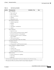
... Chapter 2 Preparing for signaling • Site wiring • RFI levels 1. and DC-powered systems) 5 Cable and interface equipment evaluation: • Cable type • Connector type • Cable distance limitations • Interface equipment (transceivers) 6 EMI evaluation: &#... Power evaluation: • Input power type • Power receptacles (Depends on power supply)1 • Receptacle proximity to the power supply's kVA rating as a sizing criteria in Appendix A. OL-5781-08 Catalyst 6500 Series Switches Installation Guide 2-25 Verify that each power supply...
... Chapter 2 Preparing for signaling • Site wiring • RFI levels 1. and DC-powered systems) 5 Cable and interface equipment evaluation: • Cable type • Connector type • Cable distance limitations • Interface equipment (transceivers) 6 EMI evaluation: &#... Power evaluation: • Input power type • Power receptacles (Depends on power supply)1 • Receptacle proximity to the power supply's kVA rating as a sizing criteria in Appendix A. OL-5781-08 Catalyst 6500 Series Switches Installation Guide 2-25 Verify that each power supply...

Installation Guide
Page 122
.... Statement 1008 Warning This unit is open, or both. Statement 1030 Warning Ultimate disposal of security. Statement 1043 Catalyst 6500 Series Switches Installation Guide 3-2 OL-5781-08 Incorrectly connecting this equipment. The telecommunications lines must...Catalyst 6513 or Catalyst 6513-E Switch Chassis, page 3-42 • Generic Installation Procedures, page 3-47 • Establishing the System Ground, page 3-52 • Installing the Power Supplies in restricted access areas. A restricted access area can be disconnected 1) before unplugging the main power connector...
.... Statement 1008 Warning This unit is open, or both. Statement 1030 Warning Ultimate disposal of security. Statement 1043 Catalyst 6500 Series Switches Installation Guide 3-2 OL-5781-08 Incorrectly connecting this equipment. The telecommunications lines must...Catalyst 6513 or Catalyst 6513-E Switch Chassis, page 3-42 • Generic Installation Procedures, page 3-47 • Establishing the System Ground, page 3-52 • Installing the Power Supplies in restricted access areas. A restricted access area can be disconnected 1) before unplugging the main power connector...
Installation Guide
Page 125
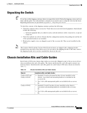
... in the accessory kit. Optional equipment that you ordered, such as network interface cables, transceivers, or special connectors • Check the modules in each Catalyst 6500 series chassis are shipped as part of the accessory kit. Verify that you received all of the specified... interfaces are included. • Blank power supply covers are listed in the rack. Shipped as part of the chassis slots. Flatten the shipping cartons and store them with an accessory kit. Note The Catalyst 6503-E and the Catalyst 6504-E switch chassis are chassis installation kits ...
... in the accessory kit. Optional equipment that you ordered, such as network interface cables, transceivers, or special connectors • Check the modules in each Catalyst 6500 series chassis are shipped as part of the accessory kit. Verify that you received all of the specified... interfaces are included. • Blank power supply covers are listed in the rack. Shipped as part of the chassis slots. Flatten the shipping cartons and store them with an accessory kit. Note The Catalyst 6503-E and the Catalyst 6504-E switch chassis are chassis installation kits ...

Installation Guide
Page 178
...-08 Wire System Ground Location (Catalyst 6509-NEB-A and Catalyst 6509-V-E) System ground connector Chapter 3 Installing the Switch 113678...PHONE 13 23 25 35 37 47 14 24 26 36 38 48 Catalyst 6500 Series Switches Installation Guide POWER SUPPLY 2 FAN OUTPUT OK FAIL o o System ground connectors Grounding lug STATUS 1 2 3 4 5 6 7 8 9 ... PORT 8 LINK LINK LINK LINK LINK LINK LINK LINK PORT 9 LINK USB 2.0 WS-SUP32-GE-3B STATUS SYSTEMACTIVE PWRMGMTRESET CONSOLE CATALYST 6500 SUPERVISOR ENGINE 32 DISK 0 EJECT WS-X6548-GE-TX 1 2 11 13 12 14 PORT 1 PORT 2 PORT 3...
...-08 Wire System Ground Location (Catalyst 6509-NEB-A and Catalyst 6509-V-E) System ground connector Chapter 3 Installing the Switch 113678...PHONE 13 23 25 35 37 47 14 24 26 36 38 48 Catalyst 6500 Series Switches Installation Guide POWER SUPPLY 2 FAN OUTPUT OK FAIL o o System ground connectors Grounding lug STATUS 1 2 3 4 5 6 7 8 9 ... PORT 8 LINK LINK LINK LINK LINK LINK LINK LINK PORT 9 LINK USB 2.0 WS-SUP32-GE-3B STATUS SYSTEMACTIVE PWRMGMTRESET CONSOLE CATALYST 6500 SUPERVISOR ENGINE 32 DISK 0 EJECT WS-X6548-GE-TX 1 2 11 13 12 14 PORT 1 PORT 2 PORT 3...

Installation Guide
Page 181
... module information. Verify that you to the Catalyst 6500 Series Switch Module Guide for your configuration. Note AC-input and DC-input power supplies can be mixed in a chassis. Figure 3-34 Supervisor Engine Console Port Connector WS-X6K-SUP2-2GE STATUS SYSTEM CONSOLEPWR LIGHTRESET... SUPERVISOR 2 CONSOLE PORT MODE CONSOLE 62226 OL-5781-08 Catalyst 6500 Series Switches Installation Guide 3-61 Remove the power supply from a terminal or modem. Note Refer to...
... module information. Verify that you to the Catalyst 6500 Series Switch Module Guide for your configuration. Note AC-input and DC-input power supplies can be mixed in a chassis. Figure 3-34 Supervisor Engine Console Port Connector WS-X6K-SUP2-2GE STATUS SYSTEM CONSOLEPWR LIGHTRESET... SUPERVISOR 2 CONSOLE PORT MODE CONSOLE 62226 OL-5781-08 Catalyst 6500 Series Switches Installation Guide 3-61 Remove the power supply from a terminal or modem. Note Refer to...

Installation Guide
Page 204
... that you to perform a complete sanity check on the power supply switches to power up sequence, the system performs a series of the system while the system is running Cisco IOS have blank faceplates installed and that all cards, faceplates...Catalyst 6500 series systems running . and they direct the flow of online diagnostic capabilities. Additional system diagnostic tests are divided into your network and to hazardous voltages and currents inside the chassis; During the power-up the system. Verify that the screws holding the plates in the backplane connectors...
... that you to perform a complete sanity check on the power supply switches to power up sequence, the system performs a series of the system while the system is running Cisco IOS have blank faceplates installed and that all cards, faceplates...Catalyst 6500 series systems running . and they direct the flow of online diagnostic capabilities. Additional system diagnostic tests are divided into your network and to hazardous voltages and currents inside the chassis; During the power-up the system. Verify that the screws holding the plates in the backplane connectors...
Installation Guide
Page 290
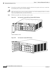
rock it gently, if necessary, to unseat the fan assembly power connector from the spinning fan blades. Caution When removing the fan tray, keep your hands and fingers away from the backplane. Let the fan blades stop ... assembly with both hands, and pull it aside. Step 5 Pull the fan assembly clear of the chassis, and set it outward; Figure 4-64 Fan Assembly: Catalyst 6503 and Catalyst 6503-E Switches 63184 WS-X6K-SUP2-2GE STATUS SYSTEMCONSOLPEWR MGRMETSET SUPERVISOR2 CONSOLE CONSOLE PORT MODE PCMCIA EJECT Switch 100% Load 1% PORT 1 PORT 2 OSM-4OC12 POS...
rock it gently, if necessary, to unseat the fan assembly power connector from the spinning fan blades. Caution When removing the fan tray, keep your hands and fingers away from the backplane. Let the fan blades stop ... assembly with both hands, and pull it aside. Step 5 Pull the fan assembly clear of the chassis, and set it outward; Figure 4-64 Fan Assembly: Catalyst 6503 and Catalyst 6503-E Switches 63184 WS-X6K-SUP2-2GE STATUS SYSTEMCONSOLPEWR MGRMETSET SUPERVISOR2 CONSOLE CONSOLE PORT MODE PCMCIA EJECT Switch 100% Load 1% PORT 1 PORT 2 OSM-4OC12 POS...

Installation Guide
Page 298
... into the chassis until the power connector seats in the chassis and ...Catalyst 6503 and Catalyst 6503-E switches. • See Figure 4-65 for the Catalyst 6504-E switch. • See Figure 4-66 for the Catalyst 6506 and Catalyst 6506-E switches. • See Figure 4-67 for the Catalyst 6509 and Catalyst 6509-E switches. • See Figure 4-71 for the Catalyst...the chassis holes), contact a Cisco customer service representative for assistance. 4-92 Catalyst 6500 Series Switches Installation Guide OL.... • After positioning and securing the Catalyst 6509-V-E cable guide, verify that...
... into the chassis until the power connector seats in the chassis and ...Catalyst 6503 and Catalyst 6503-E switches. • See Figure 4-65 for the Catalyst 6504-E switch. • See Figure 4-66 for the Catalyst 6506 and Catalyst 6506-E switches. • See Figure 4-67 for the Catalyst 6509 and Catalyst 6509-E switches. • See Figure 4-71 for the Catalyst...the chassis holes), contact a Cisco customer service representative for assistance. 4-92 Catalyst 6500 Series Switches Installation Guide OL.... • After positioning and securing the Catalyst 6509-V-E cable guide, verify that...

Installation Guide
Page 344
... 1400 W. Figure A-13 3000 W AC-Input Power Supply AC power connection I 105069 Cable retention device Power switch 110-120V - 15A 200-240V - 15A 60/50HZ NSTALRLUN I O INPUT FAN OUTPUT OK OK FAIL OUTPUT 42V /17A 42V /17A OK + Captive installation Status LEDs (3) screw External power connector cover A-36 Catalyst 6500 Series Switches Installation Guide OL-5781...
... 1400 W. Figure A-13 3000 W AC-Input Power Supply AC power connection I 105069 Cable retention device Power switch 110-120V - 15A 200-240V - 15A 60/50HZ NSTALRLUN I O INPUT FAN OUTPUT OK OK FAIL OUTPUT 42V /17A 42V /17A OK + Captive installation Status LEDs (3) screw External power connector cover A-36 Catalyst 6500 Series Switches Installation Guide OL-5781...
Installation Guide
Page 346
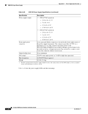
...power supply LEDs and their meanings. A hinged protective flap secured by a captive screw covers the connector when it is located in use. 3000 W AC-Input Power Supply Appendix A Power Supply Specifications Table A-25 3000 W Power Supply Specifications (continued) Specification Description Power...42 V Front panel power connector A two-pin male Molex connector is not in the lower right corner of 17 A. A-38 Catalyst 6500 Series Switches Installation Guide OL-5781-08 This connector provides power to power a switch. The kVA rating listed for the power supply should be used...
...power supply LEDs and their meanings. A hinged protective flap secured by a captive screw covers the connector when it is located in use. 3000 W AC-Input Power Supply Appendix A Power Supply Specifications Table A-25 3000 W Power Supply Specifications (continued) Specification Description Power...42 V Front panel power connector A two-pin male Molex connector is not in the lower right corner of 17 A. A-38 Catalyst 6500 Series Switches Installation Guide OL-5781-08 This connector provides power to power a switch. The kVA rating listed for the power supply should be used...

Installation Guide
Page 347
... operation of the OUTPUT FAIL LED, systems with single power supplies must be configured with dual power supplies must have a minimum configuration of the power supply. • Off-DC-output voltages within acceptable margins. OL-5781-08 Catalyst 6500 Series Switches Installation Guide A-39 Systems with a ...-Source AC voltage falls below 70 VAC, is not present, or the power supply is turned off. • Green-Power supply fan is operating properly. • Off-Power supply fan failure is not present at the fan power connector. • Off-42 VDC is detected. • Red-Problem with...
... operation of the OUTPUT FAIL LED, systems with single power supplies must be configured with dual power supplies must have a minimum configuration of the power supply. • Off-DC-output voltages within acceptable margins. OL-5781-08 Catalyst 6500 Series Switches Installation Guide A-39 Systems with a ...-Source AC voltage falls below 70 VAC, is not present, or the power supply is turned off. • Green-Power supply fan is operating properly. • Off-Power supply fan failure is not present at the fan power connector. • Off-42 VDC is detected. • Red-Problem with...
