Installation Guide
Page 7
...Installing the Cable Management System (Optional) 3-40 What is Next 3-42 Optional Installation Kits 3-42 Installing a Catalyst 6513 or Catalyst 6513-E Switch Chassis 3-42 Installation Accessory Kit 3-42 L Brackets on the Catalyst 6513 and Catalyst 6513-E Switch Chassis 3-43 Installing the 3 RU Rack-Mount Shelf Kit 3-44 Rack-Mounting the Chassis 3-... the Stabilizer Bracket Kit 3-50 Establishing the System Ground 3-52 Required Tools and Equipment 3-53 Connecting the System Ground 3-53 Installing the Power Supplies in the Switch Chassis 3-61 Catalyst 6500 Series Switches Installation Guide vii
...Installing the Cable Management System (Optional) 3-40 What is Next 3-42 Optional Installation Kits 3-42 Installing a Catalyst 6513 or Catalyst 6513-E Switch Chassis 3-42 Installation Accessory Kit 3-42 L Brackets on the Catalyst 6513 and Catalyst 6513-E Switch Chassis 3-43 Installing the 3 RU Rack-Mount Shelf Kit 3-44 Rack-Mounting the Chassis 3-... the Stabilizer Bracket Kit 3-50 Establishing the System Ground 3-52 Required Tools and Equipment 3-53 Connecting the System Ground 3-53 Installing the Power Supplies in the Switch Chassis 3-61 Catalyst 6500 Series Switches Installation Guide vii
Installation Guide
Page 8
... Ports 3-63 Using the Catalyst 6509-V-E Cable Management System 3-78 Verifying Switch Chassis Installation 3-84 Online Diagnostics 3-84 Removal and Replacement Procedures 4-1 Online Insertion and Removal 4-1 Removing and Installing the AC-Input Power Supplies 4-2 Removing and Installing the 950 W and 1400 W AC-Input Power Supplies 4-3 Removing and Installing the 2700 W AC-Input Power Supply 4-6 Removing and Installing...
... Ports 3-63 Using the Catalyst 6509-V-E Cable Management System 3-78 Verifying Switch Chassis Installation 3-84 Online Diagnostics 3-84 Removal and Replacement Procedures 4-1 Online Insertion and Removal 4-1 Removing and Installing the AC-Input Power Supplies 4-2 Removing and Installing the 950 W and 1400 W AC-Input Power Supplies 4-3 Removing and Installing the 2700 W AC-Input Power Supply 4-6 Removing and Installing...
Installation Guide
Page 9
... W Power Supply Specifications A-42 4000 W Power Supply AC Power Cords A-46 6000 W AC-Input and DC-Input Power Supplies A-46 6000 W Power Supply Specifications A-48 6000 W Power Supply AC Power Cords A-53 8700 W AC-Input Power Supply A-54 8700 W Power Supply Specifications A-55 Remote Power Cycling Feature A-60 8700 W Power Supply AC Power Cords A-62 AC Power Cord Illustrations A-63 Power Supply Redundancy A-73 Transceivers, Module Connectors, and Cable Specifications B-1 Pluggable Transceivers B-1 Catalyst 6500...
... W Power Supply Specifications A-42 4000 W Power Supply AC Power Cords A-46 6000 W AC-Input and DC-Input Power Supplies A-46 6000 W Power Supply Specifications A-48 6000 W Power Supply AC Power Cords A-53 8700 W AC-Input Power Supply A-54 8700 W Power Supply Specifications A-55 Remote Power Cycling Feature A-60 8700 W Power Supply AC Power Cords A-62 AC Power Cord Illustrations A-63 Power Supply Redundancy A-73 Transceivers, Module Connectors, and Cable Specifications B-1 Pluggable Transceivers B-1 Catalyst 6500...

Installation Guide
Page 10
... Cleaning the Fiber-Optic Connectors B-38 Repacking the Switch C-1 Chassis and Module Power and Heat Values D-1 Troubleshooting E-1 Getting Started E-1 Solving Problems at the System Component Level E-2 Identifying Startup Problems E-3 Troubleshooting the Power Supply E-4 Troubleshooting the Fan Assembly E-5 Troubleshooting Modules E-5 STATUS LED Indications E-5 Contacting Customer Service E-7 Catalyst 6500 Series Switches Installation Guide x OL-5781-08
... Cleaning the Fiber-Optic Connectors B-38 Repacking the Switch C-1 Chassis and Module Power and Heat Values D-1 Troubleshooting E-1 Getting Started E-1 Solving Problems at the System Component Level E-2 Identifying Startup Problems E-3 Troubleshooting the Power Supply E-4 Troubleshooting the Fan Assembly E-5 Troubleshooting Modules E-5 STATUS LED Indications E-5 Contacting Customer Service E-7 Catalyst 6500 Series Switches Installation Guide x OL-5781-08
Installation Guide
Page 11
... 1 Chapter 2 Chapter 3 Chapter 4 Appendix A Title Description Product Overview Describes and lists the hardware features and functionality of the chassis and specifications tables for the available Catalyst 6500 series switch AC-input and DC-input power supplies. Procedures are also provided for Installation Describes things you need to install your site before installing the...
... 1 Chapter 2 Chapter 3 Chapter 4 Appendix A Title Description Product Overview Describes and lists the hardware features and functionality of the chassis and specifications tables for the available Catalyst 6500 series switch AC-input and DC-input power supplies. Procedures are also provided for Installation Describes things you need to install your site before installing the...
Installation Guide
Page 22
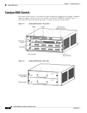
Figure 1-1 Catalyst 6503 Switch-Front View PEM 1 PEM 2 ESD ground strap connection 91239 Supervisor Engine Modules WS-SUP32-GE-3B STATUSSYSTEMACTIVE PWRMGMTRESET CATALYST 6500 SUPERVISOR ENGINE 32 CONSOLE WS-X6516-GE-T X 1 2 EJECT 3 4 DISK 0 16 PORT 1000 BASE...) Figure 1-2 Catalyst 6503 Switch-Rear View 63031 Power supply 2 (redundant) Power supply 1 INPUT FAN OUTPUT OK OK FAIL INPUT FAN OUTPUT OK OK FAIL Catalyst 6500 Series Switches Installation Guide 1-2 OL-5781-08 Catalyst 6503 Switch Chapter 1 Product Overview Catalyst 6503 Switch The Catalyst 6503 switch is NEBS...
Figure 1-1 Catalyst 6503 Switch-Front View PEM 1 PEM 2 ESD ground strap connection 91239 Supervisor Engine Modules WS-SUP32-GE-3B STATUSSYSTEMACTIVE PWRMGMTRESET CATALYST 6500 SUPERVISOR ENGINE 32 CONSOLE WS-X6516-GE-T X 1 2 EJECT 3 4 DISK 0 16 PORT 1000 BASE...) Figure 1-2 Catalyst 6503 Switch-Rear View 63031 Power supply 2 (redundant) Power supply 1 INPUT FAN OUTPUT OK OK FAIL INPUT FAN OUTPUT OK OK FAIL Catalyst 6500 Series Switches Installation Guide 1-2 OL-5781-08 Catalyst 6503 Switch Chapter 1 Product Overview Catalyst 6503 Switch The Catalyst 6503 switch is NEBS...
Installation Guide
Page 25
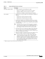
... fan tray and one DC-input. Chapter 1 Product Overview Catalyst 6503 Switch Table 1-1 Catalyst 6503 Switch Features (continued) Feature Power Entry Module (PEM)1 Power supplies Description • A PEM is installed in the upper power supply bay. PEM-15A-AC (PEM for 950 W DC-input power supplies). - The following power supplies are required for each installed power supply. - Source AC can be installed. Failure to meet...
... fan tray and one DC-input. Chapter 1 Product Overview Catalyst 6503 Switch Table 1-1 Catalyst 6503 Switch Features (continued) Feature Power Entry Module (PEM)1 Power supplies Description • A PEM is installed in the upper power supply bay. PEM-15A-AC (PEM for 950 W DC-input power supplies). - The following power supplies are required for each installed power supply. - Source AC can be installed. Failure to meet...
Installation Guide
Page 27
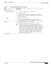
...input PEMs, and 2 AC-input power supplies: 85.4 lb (38.7 kg). • FAN-MOD-3 (Standard fan tray)-170 CFM • FAN-MOD-3HS (Optional high-speed fan tray)-270 CFM Note To maintain proper air circulation through the Catalyst switch chassis, we recommend that you...the hot air exhaust on one chassis and the air intake on another chassis. OL-5781-08 Catalyst 6500 Series Switches Installation Guide 1-7 Chapter 1 Product Overview Catalyst 6503 Switch Table 1-2 Catalyst 6503 Switch Specifications (continued) Item Physical Characteristics Dimensions (H x W x D) Weight Airflow 1. You should...
...input PEMs, and 2 AC-input power supplies: 85.4 lb (38.7 kg). • FAN-MOD-3 (Standard fan tray)-170 CFM • FAN-MOD-3HS (Optional high-speed fan tray)-270 CFM Note To maintain proper air circulation through the Catalyst switch chassis, we recommend that you...the hot air exhaust on one chassis and the air intake on another chassis. OL-5781-08 Catalyst 6500 Series Switches Installation Guide 1-7 Chapter 1 Product Overview Catalyst 6503 Switch Table 1-2 Catalyst 6503 Switch Specifications (continued) Item Physical Characteristics Dimensions (H x W x D) Weight Airflow 1. You should...
Installation Guide
Page 28
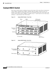
... chassis and Figure 1-4 shows the rear view of the Catalyst 6503 switch. Catalyst 6503-E Switch Chapter 1 Product Overview Catalyst 6503-E Switch The Catalyst 6503-E switch is NEBS L3 compliant. The 3-slot horizontal chassis supports redundant power supplies, redundant supervisor engines, and slots for up to bottom) Figure 1-4 Catalyst 6503-E Switch-Rear View 63031 Power supply 2 (redundant) Power supply 1 INPUT FAN OUTPUT OK OK FAIL INPUT FAN...
... chassis and Figure 1-4 shows the rear view of the Catalyst 6503 switch. Catalyst 6503-E Switch Chapter 1 Product Overview Catalyst 6503-E Switch The Catalyst 6503-E switch is NEBS L3 compliant. The 3-slot horizontal chassis supports redundant power supplies, redundant supervisor engines, and slots for up to bottom) Figure 1-4 Catalyst 6503-E Switch-Rear View 63031 Power supply 2 (redundant) Power supply 1 INPUT FAN OUTPUT OK OK FAIL INPUT FAN...
Installation Guide
Page 30
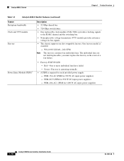
...event of a fan failure. PEM-DC/3 (PEM for 1400 W AC-input power supplies). 1-10 Catalyst 6500 Series Switches Installation Guide OL-5781-08 Catalyst 6503-E Switch Chapter 1 Product Overview Table 1-3 Catalyst 6503-E Switch Features (continued) Feature Backplane bandwidth Clock and VTT module Fan tray Description...the EOBC channel and the switching bus. • Nonreplaceable voltage termination (VTT) module provides reference voltage for 950 W AC-input power supplies). - PEM-15A-AC (PEM for bus signals. • The chassis supports one hot-swappable fan tray. Green-Fan tray is...
...event of a fan failure. PEM-DC/3 (PEM for 1400 W AC-input power supplies). 1-10 Catalyst 6500 Series Switches Installation Guide OL-5781-08 Catalyst 6503-E Switch Chapter 1 Product Overview Table 1-3 Catalyst 6503-E Switch Features (continued) Feature Backplane bandwidth Clock and VTT module Fan tray Description...the EOBC channel and the switching bus. • Nonreplaceable voltage termination (VTT) module provides reference voltage for 950 W AC-input power supplies). - PEM-15A-AC (PEM for bus signals. • The chassis supports one hot-swappable fan tray. Green-Fan tray is...
Installation Guide
Page 31
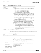
Chapter 1 Product Overview Catalyst 6503-E Switch Table 1-3 Catalyst 6503-E Switch Features (continued) Feature Description Power supplies • Supports one DC-input. Power supplies can cause a false power supply output fail signal. 1. Note For proper operation of the power supply OUTPUT FAIL LED, systems with single power supplies must have a minimum configuration of one fan tray, one supervisor engine, and one supervisor engine. PWR-1400-AC...
Chapter 1 Product Overview Catalyst 6503-E Switch Table 1-3 Catalyst 6503-E Switch Features (continued) Feature Description Power supplies • Supports one DC-input. Power supplies can cause a false power supply output fail signal. 1. Note For proper operation of the power supply OUTPUT FAIL LED, systems with single power supplies must have a minimum configuration of one fan tray, one supervisor engine, and one supervisor engine. PWR-1400-AC...
Installation Guide
Page 32
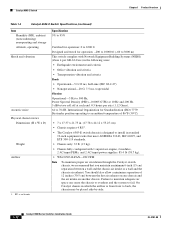
... supervisor engine, 2 modules, 2 AC-input PEMs, and 2 AC-input power supplies: 85.4 lb (38.7 kg). • WS-C6503-E-FAN-282 CFM Note To maintain proper air circulation through the Catalyst switch chassis, we recommend that you maintain a minimum 6-inch (15 cm) ...12 inches (30.5 cm) between a wall and the chassis air intake or a wall and the chassis air exhaust. Catalyst 6503-E Switch Chapter 1 Product Overview Table 1-4 Catalyst 6503-E Switch Specifications (continued) Item Humidity (RH), ambient (noncondensing) nonoperating and storage Altitude, operating Shock and vibration Acoustic ...
... supervisor engine, 2 modules, 2 AC-input PEMs, and 2 AC-input power supplies: 85.4 lb (38.7 kg). • WS-C6503-E-FAN-282 CFM Note To maintain proper air circulation through the Catalyst switch chassis, we recommend that you maintain a minimum 6-inch (15 cm) ...12 inches (30.5 cm) between a wall and the chassis air intake or a wall and the chassis air exhaust. Catalyst 6503-E Switch Chapter 1 Product Overview Table 1-4 Catalyst 6503-E Switch Specifications (continued) Item Humidity (RH), ambient (noncondensing) nonoperating and storage Altitude, operating Shock and vibration Acoustic ...
Installation Guide
Page 33
... View Slots 1-4 (top to three modules. Chapter 1 Product Overview Catalyst 6504-E Switch Catalyst 6504-E Switch The Catalyst 6504-E switch is NEBS L3 compliant. The Catalyst 6504-E switch chassis is a 4-slot horizontal chassis that supports redundant power supplies, redundant supervisor engines, and slots for up to bottom) Power Supply 2 (redundant) Power Supply 1 100-240V-16A 50/60Hz 100-240V-16A 50...
... View Slots 1-4 (top to three modules. Chapter 1 Product Overview Catalyst 6504-E Switch Catalyst 6504-E Switch The Catalyst 6504-E switch is NEBS L3 compliant. The Catalyst 6504-E switch chassis is a 4-slot horizontal chassis that supports redundant power supplies, redundant supervisor engines, and slots for up to bottom) Power Supply 2 (redundant) Power Supply 1 100-240V-16A 50/60Hz 100-240V-16A 50...
Installation Guide
Page 35
.../4 (2700 W DC-input power supply). • Installed power supplies can cause a false power supply output fail signal. Power supplies can be out of phase between multiple power supplies or multiple AC-power plugs on the same power supply because all AC power supply inputs are isolated. • Single power supplies are installed in either redundant or combined mode. • All Catalyst 6500 series AC-input power supplies require single-phase...
.../4 (2700 W DC-input power supply). • Installed power supplies can cause a false power supply output fail signal. Power supplies can be out of phase between multiple power supplies or multiple AC-power plugs on the same power supply because all AC power supply inputs are isolated. • Single power supplies are installed in either redundant or combined mode. • All Catalyst 6500 series AC-input power supplies require single-phase...
Installation Guide
Page 37
... Guide 1-17 On Catalyst chassis in standard 19-inch equipment racks that meet ANSI/EIA 310-D, IEC 60297, and ETS 300-119 standards. • Chassis only: 27 lb (12.25 kg). • Chassis fully configured with 2 supervisor engines, 2 modules, and 2 AC-input power supplies: 97 lb (43....99 kg). • FAN-MOD-4HS-300 CFM Note To maintain proper air circulation through the Catalyst switch chassis, we recommend that you maintain a minimum 6-inch (15 cm) separation between the...
... Guide 1-17 On Catalyst chassis in standard 19-inch equipment racks that meet ANSI/EIA 310-D, IEC 60297, and ETS 300-119 standards. • Chassis only: 27 lb (12.25 kg). • Chassis fully configured with 2 supervisor engines, 2 modules, and 2 AC-input power supplies: 97 lb (43....99 kg). • FAN-MOD-4HS-300 CFM Note To maintain proper air circulation through the Catalyst switch chassis, we recommend that you maintain a minimum 6-inch (15 cm) separation between the...

Installation Guide
Page 38
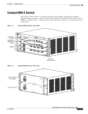
The chassis is a 6-slot horizontal chassis supporting redundant power supplies, redundant supervisor engines, and slots for up to five modules. Figure 1-7 Catalyst 6506 Switch LINK LINK LINK Switching modules Fan assembly Supervisor engine Redundant supervisor engine 1 2 3 ...OK FAIL INPUT OK FAN OUTPUT OK FAIL Power supply 1 Power supply 2 ESD ground strap (redundant) connector 18224 1-18 Catalyst 6500 Series Switches Installation Guide OL-5781-08 Catalyst 6506 Switch Chapter 1 Product Overview Catalyst 6506 Switch The Catalyst 6506 switch is NEBS L3 compliant. Figure ...
The chassis is a 6-slot horizontal chassis supporting redundant power supplies, redundant supervisor engines, and slots for up to five modules. Figure 1-7 Catalyst 6506 Switch LINK LINK LINK Switching modules Fan assembly Supervisor engine Redundant supervisor engine 1 2 3 ...OK FAIL INPUT OK FAN OUTPUT OK FAIL Power supply 1 Power supply 2 ESD ground strap (redundant) connector 18224 1-18 Catalyst 6500 Series Switches Installation Guide OL-5781-08 Catalyst 6506 Switch Chapter 1 Product Overview Catalyst 6506 Switch The Catalyst 6506 switch is NEBS L3 compliant. Figure ...
Installation Guide
Page 39
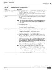
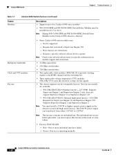
... redundant supervisor engines, both supervisor engines must also install a 2500 W or higher capacity power supply in slot 1 or slot 2. - Check your software release notes for any restrictions on the redundant supervisor engine in switching fabric. Chapter 1 Product Overview Catalyst 6506 Switch Table 1-7 lists the features of module that all require the high-speed...
... redundant supervisor engines, both supervisor engines must also install a 2500 W or higher capacity power supply in slot 1 or slot 2. - Check your software release notes for any restrictions on the redundant supervisor engine in switching fabric. Chapter 1 Product Overview Catalyst 6506 Switch Table 1-7 lists the features of module that all require the high-speed...
Installation Guide
Page 40
Require that you must replace the fan tray in the Catalyst 6506 chassis is operating normally. 1-20 Catalyst 6500 Series Switches Installation Guide OL-5781-08 The individual fans are available: - The 2500 W power supply can be supported - you install a Supervisor Engine 720 - Green-Fan tray... Engine 1 and Supervisor Engine 2. Have chassis slot restrictions - Note You must install a 2500 W or higher capacity power supply in slot 5 or slot 6. Supports Supervisor Engine 1 and Supervisor Engine 2 only; Note The fan trays contains six individual fans. Not be...
Require that you must replace the fan tray in the Catalyst 6506 chassis is operating normally. 1-20 Catalyst 6500 Series Switches Installation Guide OL-5781-08 The individual fans are available: - The 2500 W power supply can be supported - you install a Supervisor Engine 720 - Green-Fan tray... Engine 1 and Supervisor Engine 2. Have chassis slot restrictions - Note You must install a 2500 W or higher capacity power supply in slot 5 or slot 6. Supports Supervisor Engine 1 and Supervisor Engine 2 only; Note The fan trays contains six individual fans. Not be...

Installation Guide
Page 41
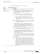
... W DC-input power supply). - WS-CAC-4000W-INT (4000 W AC-input power supply). - Power supplies can cause a false power supply output fail signal. WS-CDC-2500W (2500 W DC-input power supply). - WS-CAC-6000W (6000 W AC-input power supply). - Note The 6000 W AC-input and DC-input power supplies, and the 8700 W AC-input power supply are installed in the Catalyst 6506 chassis. • Installed power supplies can be...
... W DC-input power supply). - WS-CAC-4000W-INT (4000 W AC-input power supply). - Power supplies can cause a false power supply output fail signal. WS-CDC-2500W (2500 W DC-input power supply). - WS-CAC-6000W (6000 W AC-input power supply). - Note The 6000 W AC-input and DC-input power supplies, and the 8700 W AC-input power supply are installed in the Catalyst 6506 chassis. • Installed power supplies can be...
Installation Guide
Page 43
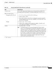
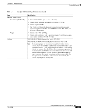
... 45 lb (20.4 kg). • Chassis fully configured with 1 supervisor engine, 5 switching modules, and 2 power supplies: 156.6 lb (71.0 kg). On Catalyst chassis in standard 19-inch equipment racks that you maintain a minimum 6-inch (15 cm) separation between the hot air...air space can cause the chassis to overheat and the system to back, the chassis may be placed side-by-side. Chapter 1 Product Overview Catalyst 6506 Switch Table 1-8 Catalyst 6506 Switch Specifications (continued) Item Physical characteristics Dimensions (H x W x D) Weight Airflow Specification • 20.1 x 17.2 x 18.1...
... 45 lb (20.4 kg). • Chassis fully configured with 1 supervisor engine, 5 switching modules, and 2 power supplies: 156.6 lb (71.0 kg). On Catalyst chassis in standard 19-inch equipment racks that you maintain a minimum 6-inch (15 cm) separation between the hot air...air space can cause the chassis to overheat and the system to back, the chassis may be placed side-by-side. Chapter 1 Product Overview Catalyst 6506 Switch Table 1-8 Catalyst 6506 Switch Specifications (continued) Item Physical characteristics Dimensions (H x W x D) Weight Airflow Specification • 20.1 x 17.2 x 18.1...
