

Configuration Guide
Page 4
...-Input and DC-Input Power Supply Overview 1-46 Arbiter Overview 1-50 Chassis Interface Overview 1-50 Fan Tray and Blower Assembly Overview 1-51 Cisco 7505 Fan Tray Assembly 1-52 Cisco 7507 and Cisco 7507-MX Blower Assembly 1-52 Cisco 7513, Cisco 7513-MX, and Cisco 7576 Blower Module Assembly 1-53 Interface Processor Overview 1-54 System Software Overview 1-56 Preparing for Installation 2-1 Tools...
...-Input and DC-Input Power Supply Overview 1-46 Arbiter Overview 1-50 Chassis Interface Overview 1-50 Fan Tray and Blower Assembly Overview 1-51 Cisco 7505 Fan Tray Assembly 1-52 Cisco 7507 and Cisco 7507-MX Blower Assembly 1-52 Cisco 7513, Cisco 7513-MX, and Cisco 7576 Blower Module Assembly 1-53 Interface Processor Overview 1-54 System Software Overview 1-56 Preparing for Installation 2-1 Tools...

Configuration Guide
Page 7
... Chassis Interface in the Cisco 7507 and Cisco 7507-MX 6-12 Removing and Replacing the Cisco 7507 and Cisco 7507-MX LED Board 6-13 Removing and Replacing the Cisco 7507 and Cisco 7507-MX Blower Assembly 6-15 Maintaining Your Cisco 7513, Cisco 7513-MX, and Cisco 7576 Router 7-1 Tools Required for Maintenance Procedures 7-2 Maintenance Procedures for the Cisco 7513, Cisco 7513-MX, and Cisco 7576 7-2 Removing Cisco 7513, Cisco 7513-MX, and Cisco...
... Chassis Interface in the Cisco 7507 and Cisco 7507-MX 6-12 Removing and Replacing the Cisco 7507 and Cisco 7507-MX LED Board 6-13 Removing and Replacing the Cisco 7507 and Cisco 7507-MX Blower Assembly 6-15 Maintaining Your Cisco 7513, Cisco 7513-MX, and Cisco 7576 Router 7-1 Tools Required for Maintenance Procedures 7-2 Maintenance Procedures for the Cisco 7513, Cisco 7513-MX, and Cisco 7576 7-2 Removing Cisco 7513, Cisco 7513-MX, and Cisco...

Configuration Guide
Page 8
... Cage Assembly 7-9 Removing and Replacing the Cisco 7513, Cisco 7513-MX, and Cisco 7576 Blower Module 7-10 Removing and Replacing the Cisco 7513, Cisco 7513-MX, and Cisco 7576 Chassis Cover Panels 7-11 Removing and Replacing the Cisco 7513, Cisco 7513-MX, and Cisco 7576 Backplane Maintenance Cover 7-13 Removing and Replacing the Chassis Interface in the Cisco 7513, Cisco 7513-MX, and Cisco 7576 7-14 Troubleshooting a Cisco 7500 Series Router 8-1 Troubleshooting Overview 8-2 Problem...
... Cage Assembly 7-9 Removing and Replacing the Cisco 7513, Cisco 7513-MX, and Cisco 7576 Blower Module 7-10 Removing and Replacing the Cisco 7513, Cisco 7513-MX, and Cisco 7576 Chassis Cover Panels 7-11 Removing and Replacing the Cisco 7513, Cisco 7513-MX, and Cisco 7576 Backplane Maintenance Cover 7-13 Removing and Replacing the Chassis Interface in the Cisco 7513, Cisco 7513-MX, and Cisco 7576 7-14 Troubleshooting a Cisco 7500 Series Router 8-1 Troubleshooting Overview 8-2 Problem...

Configuration Guide
Page 23
...interface processors; CH A P T E R 1 Cisco 7500 Series Product Overview The Cisco 7500 series includes the following : • Cisco 7505 Overview, page 1-3 • Cisco 7507 Overview, page 1-6 • Cisco 7507-MX Overview, page 1-11 • Cisco 7513 Overview, page 1-15 • Cisco 7513-MX Overview, page 1-20 • Cisco 7576 Overview, page 1-25 Note The Cisco 7513, Cisco 7513-MX, and the Cisco...Arbiter Overview, page 1-50 • Chassis Interface Overview, page 1-50 • Fan Tray and Blower Assembly Overview, page 1-51 • Interface Processor Overview, page 1-54 This ...
...interface processors; CH A P T E R 1 Cisco 7500 Series Product Overview The Cisco 7500 series includes the following : • Cisco 7505 Overview, page 1-3 • Cisco 7507 Overview, page 1-6 • Cisco 7507-MX Overview, page 1-11 • Cisco 7513 Overview, page 1-15 • Cisco 7513-MX Overview, page 1-20 • Cisco 7576 Overview, page 1-25 Note The Cisco 7513, Cisco 7513-MX, and the Cisco...Arbiter Overview, page 1-50 • Chassis Interface Overview, page 1-50 • Fan Tray and Blower Assembly Overview, page 1-51 • Interface Processor Overview, page 1-54 This ...
Configuration Guide
Page 54
...ensures that ±12V is maintained within the normal operating ranges, and three temperature sensors on the RSP2. Route Switch Processor Overview Chapter 1 Cisco 7500 Series Product Overview Figure 1-20 Route Switch Processor (RSP2) Bus connector DRAM SIMMs MEMD SRAM MEMD SRAM CPU U33 U21 U12 U30 U18....) • Air-temperature sensors for environmental monitoring. (All of the logic for the environmental monitoring functions is contained on the chassis interface card.) In addition to the system software, the RSP2 contains and executes the following components: • R4600-
...ensures that ±12V is maintained within the normal operating ranges, and three temperature sensors on the RSP2. Route Switch Processor Overview Chapter 1 Cisco 7500 Series Product Overview Figure 1-20 Route Switch Processor (RSP2) Bus connector DRAM SIMMs MEMD SRAM MEMD SRAM CPU U33 U21 U12 U30 U18....) • Air-temperature sensors for environmental monitoring. (All of the logic for the environmental monitoring functions is contained on the chassis interface card.) In addition to the system software, the RSP2 contains and executes the following components: • R4600-

Configuration Guide
Page 56
...ensures that control the system. The RSP4/4+ is also compatible with the Cisco 7505, where it maintains and executes the management functions that ±12V is installed in the Cisco 7513 (see Figure 1-11) and Cisco 7576 (see Figure 1-2). Although no user-configurable jumpers on the RSP4/4+.../4+ in slot 2 or slot 3 in the Cisco 7507 (see Figure 1-5), or in slot 6 or slot 7 in slot 4 (see Figure 1-17). The RSP4/4+ uses a software-controlled configuration register, so you do not have to remove the RSP4/4+, to the chassis interface (CI) card. Figure 1-21 Route Switch Processor...
...ensures that control the system. The RSP4/4+ is also compatible with the Cisco 7505, where it maintains and executes the management functions that ±12V is installed in the Cisco 7513 (see Figure 1-11) and Cisco 7576 (see Figure 1-2). Although no user-configurable jumpers on the RSP4/4+.../4+ in slot 2 or slot 3 in the Cisco 7507 (see Figure 1-5), or in slot 6 or slot 7 in slot 4 (see Figure 1-17). The RSP4/4+ uses a software-controlled configuration register, so you do not have to remove the RSP4/4+, to the chassis interface (CI) card. Figure 1-21 Route Switch Processor...
Configuration Guide
Page 59
... of ±12V or temperature is done by the RSP8, a comparator device ensures that control the system. Cisco 7500 Series Installation and Configuration Guide 1-37 Chapter 1 Cisco 7500 Series Product Overview Figure 1-22 Route Switch Processor (RSP8) 1 Route Switch Processor Overview 2 122377 OL-...shipping configuration. The RSP8 uses a software-controlled configuration register, so you do not have to remove the RSP8 to the chassis interface (CI) card. Although no user-configurable jumpers on the RSP8 send temperature information to configure jumpers. The CI card reports ...
... of ±12V or temperature is done by the RSP8, a comparator device ensures that control the system. Cisco 7500 Series Installation and Configuration Guide 1-37 Chapter 1 Cisco 7500 Series Product Overview Figure 1-22 Route Switch Processor (RSP8) 1 Route Switch Processor Overview 2 122377 OL-...shipping configuration. The RSP8 uses a software-controlled configuration register, so you do not have to remove the RSP8 to the chassis interface (CI) card. Although no user-configurable jumpers on the RSP8 send temperature information to configure jumpers. The CI card reports ...
Configuration Guide
Page 72
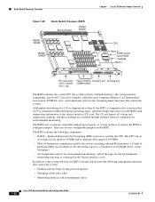
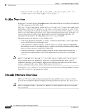
... OL-5008-03 B0 Arbiter Overview In the Cisco 7500 series routers, an internal printed circuit board called the chassis interface (CI) that each request is attached directly to identify whether or not your Cisco 7507 or Cisco 7513 includes a turbo arbiter. Refer to Replacing the... Dual Arbiter or Turbo Arbiter in conjunction with the Cisco turbo arbiter. The Cisco 7576 includes two chassis interfaces, one for router A and one for the router. ...
... OL-5008-03 B0 Arbiter Overview In the Cisco 7500 series routers, an internal printed circuit board called the chassis interface (CI) that each request is attached directly to identify whether or not your Cisco 7507 or Cisco 7513 includes a turbo arbiter. Refer to Replacing the... Dual Arbiter or Turbo Arbiter in conjunction with the Cisco turbo arbiter. The Cisco 7576 includes two chassis interfaces, one for router A and one for the router. ...
Configuration Guide
Page 73
... information, see "Removing and Replacing the Chassis Interface in the Cisco 7505" section on page 5-11, "Removing and Replacing the Chassis Interface in the Cisco 7507 and Cisco 7507-MX" section on page 6-12, and "Removing and Replacing the Chassis Interface in the Cisco 7513, Cisco 7513-MX, and Cisco 7576" section on page 7-14. (For all interface processors installed in noisy, air-conditioned rooms...
... information, see "Removing and Replacing the Chassis Interface in the Cisco 7505" section on page 5-11, "Removing and Replacing the Chassis Interface in the Cisco 7507 and Cisco 7507-MX" section on page 6-12, and "Removing and Replacing the Chassis Interface in the Cisco 7513, Cisco 7513-MX, and Cisco 7576" section on page 7-14. (For all interface processors installed in noisy, air-conditioned rooms...
Configuration Guide
Page 100
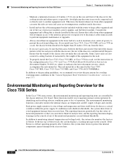
...the rack-mount kit. Environmental Monitoring and Reporting Overview for the Cisco 7507, Cisco 7507-MX, Cisco 7513, Cisco 7513-MX, and Cisco 7576 (ACS-7000RMK=). If conditions reach shutdown thresholds, the system shuts down to the interface processors or require you can enter the inlet air vents and...conditions in the lower half of a rack to prevent the rack from excessive heat. Some 2-post racks are controlled by the chassis interface (CI) board. Ensure that you to disconnect cables unnecessarily to perform equipment maintenance or upgrades. • Always install heavier equipment...
...the rack-mount kit. Environmental Monitoring and Reporting Overview for the Cisco 7507, Cisco 7507-MX, Cisco 7513, Cisco 7513-MX, and Cisco 7576 (ACS-7000RMK=). If conditions reach shutdown thresholds, the system shuts down to the interface processors or require you can enter the inlet air vents and...conditions in the lower half of a rack to prevent the rack from excessive heat. Some 2-post racks are controlled by the chassis interface (CI) board. Ensure that you to disconnect cables unnecessarily to perform equipment maintenance or upgrades. • Always install heavier equipment...
Configuration Guide
Page 101
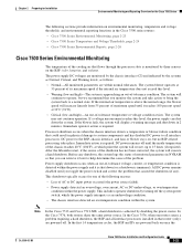
..., the system will display a warning message and shut down in 2 minutes. In the Cisco 7576, both routers share the same power source. Processor shutdown occurs when the chassis interface detects a temperature or blower-failure condition that could result in physical damage to system components...Immediate operator action is imminent). DC power to the RSP, chassis interface, and fans or blower stays on once the OL-5008-03 B0 Cisco 7500 Series Installation and Configuration Guide 2-23 Note In the Cisco 7513 and Cisco 7513-MX, a hard shutdown is achieved by three sensors on ...
..., the system will display a warning message and shut down in 2 minutes. In the Cisco 7576, both routers share the same power source. Processor shutdown occurs when the chassis interface detects a temperature or blower-failure condition that could result in physical damage to system components...Immediate operator action is imminent). DC power to the RSP, chassis interface, and fans or blower stays on once the OL-5008-03 B0 Cisco 7500 Series Installation and Configuration Guide 2-23 Note In the Cisco 7513 and Cisco 7513-MX, a hard shutdown is achieved by three sensors on ...
Configuration Guide
Page 104
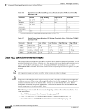
...;C 60°C Exhaust 10-40°C - - Table 2-7 Parameter +5VDC +12VDC -12VDC +24VDC Typical Power Supply-Monitored DC-Voltage Thresholds (Cisco 7513, Cisco 7513-MX, and Cisco 7576) Normal Low Critical 4.74 to 5.26 4.49 10.20 to 13.8 10.76 -10.20 to -13.80 -10.15 20....26.51 High Critical 5.52 13.24 -13.86 28.87 Cisco 7500 Series Environmental Reports The system displays warning messages on the Cisco 7576. Processor-monitored power supply shutdown is not supported on the console if chassis interface-monitored parameters exceed a desired threshold or if a blower failure ...
...;C 60°C Exhaust 10-40°C - - Table 2-7 Parameter +5VDC +12VDC -12VDC +24VDC Typical Power Supply-Monitored DC-Voltage Thresholds (Cisco 7513, Cisco 7513-MX, and Cisco 7576) Normal Low Critical 4.74 to 5.26 4.49 10.20 to 13.8 10.76 -10.20 to -13.80 -10.15 20....26.51 High Critical 5.52 13.24 -13.86 28.87 Cisco 7500 Series Environmental Reports The system displays warning messages on the Cisco 7576. Processor-monitored power supply shutdown is not supported on the console if chassis interface-monitored parameters exceed a desired threshold or if a blower failure ...

Configuration Guide
Page 161
... Started' Guide for most of Flash internal SIMM (Sector size 256K). Compiled Thu 14-Sep-95 19:03 by cisco Systems, Inc. Notice: NVRAM invalid, possibly due to support on G.703/E1 software, Version 1.0. Chassis Interface. 125K bytes of non-volatile configuration memory. 8192K bytes of Flash PCMCIA card at first-time startup...
... Started' Guide for most of Flash internal SIMM (Sector size 256K). Compiled Thu 14-Sep-95 19:03 by cisco Systems, Inc. Notice: NVRAM invalid, possibly due to support on G.703/E1 software, Version 1.0. Chassis Interface. 125K bytes of non-volatile configuration memory. 8192K bytes of Flash PCMCIA card at first-time startup...
Configuration Guide
Page 183
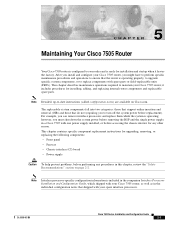
...before performing any other reason. Note Interface processor-specific configuration information is included in the companion Interface Processor Installation and Configuration Guide, which shipped with your Cisco 7505 router, as well as in a Cisco 7505 with spare parts or field...Cisco 7505 router; The replaceable system components fall into two categories: those that support online insertion and removal (OIR) and those that shipped with your order and is ready for upgrading, removing, or replacing the following components: • Front panel • Fan tray • Chassis interface...
...before performing any other reason. Note Interface processor-specific configuration information is included in the companion Interface Processor Installation and Configuration Guide, which shipped with your Cisco 7505 router, as well as in a Cisco 7505 with spare parts or field...Cisco 7505 router; The replaceable system components fall into two categories: those that support online insertion and removal (OIR) and those that shipped with your order and is ready for upgrading, removing, or replacing the following components: • Front panel • Fan tray • Chassis interface...
Configuration Guide
Page 184
... backplane cover shields the noninterface processor side of the backplane as well as the arbiter and chassis interface. The fan tray slides into the power supply bay. Cisco 7500 Series Installation and Configuration Guide 5-2 OL-5008-03 B0 When the power harness cover is...); Therefore, always turn off the system power before removing the chassis cover panel, the high current on the right side of the chassis. Tools Required for Maintenance Procedures Chapter 5 Maintaining Your Cisco 7505 Router Tools Required for Maintenance Procedures You need the following ...
... backplane cover shields the noninterface processor side of the backplane as well as the arbiter and chassis interface. The fan tray slides into the power supply bay. Cisco 7500 Series Installation and Configuration Guide 5-2 OL-5008-03 B0 When the power harness cover is...); Therefore, always turn off the system power before removing the chassis cover panel, the high current on the right side of the chassis. Tools Required for Maintenance Procedures Chapter 5 Maintaining Your Cisco 7505 Router Tools Required for Maintenance Procedures You need the following ...
Configuration Guide
Page 185
... Power Harness Cover, page 5-7 • Removing and Replacing the Cisco 7505 Backplane Cover, page 5-9 • Removing and Replacing the Chassis Interface in the Cisco 7505, page 5-11 • Removing and Replacing the Cisco 7505 Power Supply, page 5-13 Warning Before working on the chassis or near power supplies, disconnect the power cable on AC units or...
... Power Harness Cover, page 5-7 • Removing and Replacing the Cisco 7505 Backplane Cover, page 5-9 • Removing and Replacing the Chassis Interface in the Cisco 7505, page 5-11 • Removing and Replacing the Cisco 7505 Power Supply, page 5-13 Warning Before working on the chassis or near power supplies, disconnect the power cable on AC units or...

Configuration Guide
Page 190
...cover. Insert the M3 screw through Step 4 in the procedure for the Cisco 7505 Chapter 5 Maintaining Your Cisco 7505 Router Figure 5-4 Removing the Cisco 7505 Power Harness Cover H2867 Removing power harness cover Power harness cover Arbiter/chassis interface board cover Power supply Fan tray Step 3 Step 4 Step 5 Remove... and the open side facing away from you need to keep the bottom tab in the slot, push the top of the chassis. Cisco 7500 Series Installation and Configuration Guide 5-8 OL-5008-03 B0 Hold the power harness cover with the tab on the replacement procedures...
...cover. Insert the M3 screw through Step 4 in the procedure for the Cisco 7505 Chapter 5 Maintaining Your Cisco 7505 Router Figure 5-4 Removing the Cisco 7505 Power Harness Cover H2867 Removing power harness cover Power harness cover Arbiter/chassis interface board cover Power supply Fan tray Step 3 Step 4 Step 5 Remove... and the open side facing away from you need to keep the bottom tab in the slot, push the top of the chassis. Cisco 7500 Series Installation and Configuration Guide 5-8 OL-5008-03 B0 Hold the power harness cover with the tab on the replacement procedures...
Configuration Guide
Page 191
Following is the procedure for the backplane, the arbiter, and the chassis interface (CI). Do not remove any adjacent screws. Step 4 With all screws removed, carefully guide the backplane cover out and away from the chassis, remove only those screws that secure the backplane cover to remove the...See Figure 5-5.) Caution To prevent loosening the backplane from the backplane, arbiter, and CI. (See Figure 5-5.) OL-5008-03 B0 Cisco 7500 Series Installation and Configuration Guide 5-9 This procedure assumes that secure the backplane cover to the backplane. If not, see the appropriate ...
Following is the procedure for the backplane, the arbiter, and the chassis interface (CI). Do not remove any adjacent screws. Step 4 With all screws removed, carefully guide the backplane cover out and away from the chassis, remove only those screws that secure the backplane cover to remove the...See Figure 5-5.) Caution To prevent loosening the backplane from the backplane, arbiter, and CI. (See Figure 5-5.) OL-5008-03 B0 Cisco 7500 Series Installation and Configuration Guide 5-9 This procedure assumes that secure the backplane cover to the backplane. If not, see the appropriate ...
Configuration Guide
Page 193
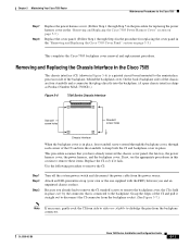
... standoffs and a connector that plugs directly into the standoffs to the backplane. Removing and Replacing the Chassis Interface in the Cisco 7505 The chassis interface (CI) (shown in place only by the connector that you have already removed the chassis cover panel, the fan tray, the power harness cover, the power harness, and the backplane cover...
... standoffs and a connector that plugs directly into the standoffs to the backplane. Removing and Replacing the Chassis Interface in the Cisco 7505 The chassis interface (CI) (shown in place only by the connector that you have already removed the chassis cover panel, the fan tray, the power harness cover, the power harness, and the backplane cover...

Configuration Guide
Page 194
... in the "Removing and Replacing the Cisco 7505 Fan Tray" section on page 5-5.) Replace the chassis cover panel. (Follow Step 1 through Step 4 in the procedure for replacing the chassis cover panel in the "Removing and Replacing the Cisco 7505 Cover Panel" section on page ...5-3.) This completes the CI replacement procedure for the Cisco 7505 Chapter 5 Maintaining Your Cisco 7505 Router Figure 5-7 Removing and Replacing the CI (Cisco 7505) Chassis interface standoffs (4) H2874 Step 4 Place the CI in an antistatic bag. Use the following procedure to replace ...
... in the "Removing and Replacing the Cisco 7505 Fan Tray" section on page 5-5.) Replace the chassis cover panel. (Follow Step 1 through Step 4 in the procedure for replacing the chassis cover panel in the "Removing and Replacing the Cisco 7505 Cover Panel" section on page ...5-3.) This completes the CI replacement procedure for the Cisco 7505 Chapter 5 Maintaining Your Cisco 7505 Router Figure 5-7 Removing and Replacing the CI (Cisco 7505) Chassis interface standoffs (4) H2874 Step 4 Place the CI in an antistatic bag. Use the following procedure to replace ...
