

Configuration Guide
Page 4
... RSP2-Cisco 7505 1-31 RSP4/4+-Cisco 7507, Cisco 7513, and Cisco 7576 1-33 RSP8-Cisco 7507-MX and Cisco 7513-MX 1-36 RSP16-Cisco 7507, Cisco 7507-MX, Cisco 7513, and Cisco 7513-MX 1-39 Common RSP Hardware Features 1-42 RSP LEDs 1-42 RSP DRAM 1-42 RSP SRAM 1-43 RSP NVRAM 1-43 RSP Flash Memory 1-43 RSP EEPROM 1-44 RSP Asynchronous Serial Ports-Console and...
... RSP2-Cisco 7505 1-31 RSP4/4+-Cisco 7507, Cisco 7513, and Cisco 7576 1-33 RSP8-Cisco 7507-MX and Cisco 7513-MX 1-36 RSP16-Cisco 7507, Cisco 7507-MX, Cisco 7513, and Cisco 7513-MX 1-39 Common RSP Hardware Features 1-42 RSP LEDs 1-42 RSP DRAM 1-42 RSP SRAM 1-43 RSP NVRAM 1-43 RSP Flash Memory 1-43 RSP EEPROM 1-44 RSP Asynchronous Serial Ports-Console and...
Configuration Guide
Page 6
Contents 4 C H A P T E R Installing the Cisco 7513, Cisco 7513-MX, and Cisco 7576 3-19 Cisco 7513, Cisco 7513-MX, and Cisco 7576 Installation Considerations 3-24 Attaching the Cisco 7513, Cisco 7513-MX, and Cisco 7576 Cable-Management Bracket 3-26 Installing Cisco 7513, Cisco 7513-MX, and Cisco 7576 Power Supplies 3-27 Connecting Power to Cisco 7513, Cisco 7513-MX, and Cisco 7576 DC-Input Power Supplies 3-29 Making Cable Connections to the RSP 3-32 Connecting a Console Terminal to the...
Contents 4 C H A P T E R Installing the Cisco 7513, Cisco 7513-MX, and Cisco 7576 3-19 Cisco 7513, Cisco 7513-MX, and Cisco 7576 Installation Considerations 3-24 Attaching the Cisco 7513, Cisco 7513-MX, and Cisco 7576 Cable-Management Bracket 3-26 Installing Cisco 7513, Cisco 7513-MX, and Cisco 7576 Power Supplies 3-27 Connecting Power to Cisco 7513, Cisco 7513-MX, and Cisco 7576 DC-Input Power Supplies 3-29 Making Cable Connections to the RSP 3-32 Connecting a Console Terminal to the...

Configuration Guide
Page 26
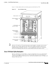
... (Front View) Captive fasteners Chapter 1 Cisco 7500 Series Product Overview H2009 Figure 1-2 shows details of the rear, interface-processor end of the Cisco 7505. CONSOLE EJECT SLOTS0LOT 1 ENABLE ROUTE SWITCH PROCESSOR RSP slot Interface processor slot 3 Interface processor slot 2 ...Interface processor slot 1 Interface processor slot 0 DC OK LED H2761 Power receptacle AC-input power supply Cisco 7505 CyBus Backplane The ...
... (Front View) Captive fasteners Chapter 1 Cisco 7500 Series Product Overview H2009 Figure 1-2 shows details of the rear, interface-processor end of the Cisco 7505. CONSOLE EJECT SLOTS0LOT 1 ENABLE ROUTE SWITCH PROCESSOR RSP slot Interface processor slot 3 Interface processor slot 2 ...Interface processor slot 1 Interface processor slot 0 DC OK LED H2761 Power receptacle AC-input power supply Cisco 7505 CyBus Backplane The ...

Configuration Guide
Page 30
...processor slots 4 through 6 (CyBus 1), as shown in Figure 1-6. Cisco 7507 Overview Chapter 1 Cisco 7500 Series Product Overview Figure 1-5 shows details on the rear, interface-processor end of the Cisco 7507. Figure 1-5 Cisco 7507 (Rear View) Captive installation screw Upper power supply Chassis grounding...ROUTE SWITCH PROCESSOR 2 NORMAL ENABLE EJECT SLOTS0LOT 1 SLAVME ASTER SLAVE/MASTER CPU HALT RESET AUX. CONSOLE ENABLE H3888 Slot 0 1 2 3 4 5 6 RSP slots Cisco 7507 Dual CyBus Backplane The dual CyBus backplane provides the physical connections for the RSPs and interface processors...
...processor slots 4 through 6 (CyBus 1), as shown in Figure 1-6. Cisco 7507 Overview Chapter 1 Cisco 7500 Series Product Overview Figure 1-5 shows details on the rear, interface-processor end of the Cisco 7507. Figure 1-5 Cisco 7507 (Rear View) Captive installation screw Upper power supply Chassis grounding...ROUTE SWITCH PROCESSOR 2 NORMAL ENABLE EJECT SLOTS0LOT 1 SLAVME ASTER SLAVE/MASTER CPU HALT RESET AUX. CONSOLE ENABLE H3888 Slot 0 1 2 3 4 5 6 RSP slots Cisco 7507 Dual CyBus Backplane The dual CyBus backplane provides the physical connections for the RSPs and interface processors...

Configuration Guide
Page 34
... Series Product Overview Figure 1-8 shows details on the rear, interface-processor end of the Cisco 7507-MX. CONSOLE ENABLE H3888 Slot 0 1 2 3 4 5 6 RSP slots Cisco 7507-MX Dual CyBus Backplane The dual CyBus backplane provides the physical connections for the RSPs and interface processors, and transfers information at up to 2....
... Series Product Overview Figure 1-8 shows details on the rear, interface-processor end of the Cisco 7507-MX. CONSOLE ENABLE H3888 Slot 0 1 2 3 4 5 6 RSP slots Cisco 7507-MX Dual CyBus Backplane The dual CyBus backplane provides the physical connections for the RSPs and interface processors, and transfers information at up to 2....

Configuration Guide
Page 39
CONSOLE ENABLE ENABLE ROUTE SWITCH PROCESSOR 2 AC OK FAN OK OUTPUT FAIL I 0 NORMAL EJECT SLOTS0LOT 1 SLAVME ASTER SLAVE/MASTER CPU HALT RESET AUX. Chapter 1 Cisco 7500 Series Product Overview Cisco 7513 Overview Figure 1-11 shows details on the rear, interface-processor end of the Cisco 7513...The dual CyBus has 13 slots: interface processor slots 0 through 12 (CyBus 1), as shown in Figure 1-12. Figure 1-11 Cisco 7513 (Rear View) Blower module Cable-management bracket Card cage and processor modules Air intake vent Power supplies Chassis grounding receptacles AC OK ...
CONSOLE ENABLE ENABLE ROUTE SWITCH PROCESSOR 2 AC OK FAN OK OUTPUT FAIL I 0 NORMAL EJECT SLOTS0LOT 1 SLAVME ASTER SLAVE/MASTER CPU HALT RESET AUX. Chapter 1 Cisco 7500 Series Product Overview Cisco 7513 Overview Figure 1-11 shows details on the rear, interface-processor end of the Cisco 7513...The dual CyBus has 13 slots: interface processor slots 0 through 12 (CyBus 1), as shown in Figure 1-12. Figure 1-11 Cisco 7513 (Rear View) Blower module Cable-management bracket Card cage and processor modules Air intake vent Power supplies Chassis grounding receptacles AC OK ...

Configuration Guide
Page 44
... Power supplies Chassis grounding receptacles AC OK FAN OK OUTPUT FAIL POWER A I 0 POWER B 122374 Cisco 7513-MX Dual CyBus Backplane The dual CyBus backplane, located at the rear of the Cisco 7513-MX. The dual CyBus has 13 slots: interface processor slots 0 through 12 (CyBus 1), as shown...shows details on the rear, interface-processor end of the Cisco 7513-MX removable card cage, provides the physical connections for the RSPs and interface processors, and transfers information at up to 2.134 Gbps (1.067 Gbps per CyBus). CONSOLE ENABLE ENABLE ROUTE SWITCH PROCESSOR 2 AC OK FAN OK ...
... Power supplies Chassis grounding receptacles AC OK FAN OK OUTPUT FAIL POWER A I 0 POWER B 122374 Cisco 7513-MX Dual CyBus Backplane The dual CyBus backplane, located at the rear of the Cisco 7513-MX. The dual CyBus has 13 slots: interface processor slots 0 through 12 (CyBus 1), as shown...shows details on the rear, interface-processor end of the Cisco 7513-MX removable card cage, provides the physical connections for the RSPs and interface processors, and transfers information at up to 2.134 Gbps (1.067 Gbps per CyBus). CONSOLE ENABLE ENABLE ROUTE SWITCH PROCESSOR 2 AC OK FAN OK ...
Configuration Guide
Page 49
... FAN OK OUTPUT FAIL POWER A I 0 POWER B 14868 Note The Cisco 7513 and Cisco 7576 use the same chassis, power supplies, cover panels, and accessories. AUX. Externally, the two models appear the same. OL-5008-03 B0 Cisco 7500 Series Installation and Configuration Guide 1-27 CONSOLE CONSOLE ENABLE ENABLE ROUTE SWITCH PROCESSOR 2 ROUTE SWITCH PROCESSOR 2 AC OK...
... FAN OK OUTPUT FAIL POWER A I 0 POWER B 14868 Note The Cisco 7513 and Cisco 7576 use the same chassis, power supplies, cover panels, and accessories. AUX. Externally, the two models appear the same. OL-5008-03 B0 Cisco 7500 Series Installation and Configuration Guide 1-27 CONSOLE CONSOLE ENABLE ENABLE ROUTE SWITCH PROCESSOR 2 ROUTE SWITCH PROCESSOR 2 AC OK...
Configuration Guide
Page 54
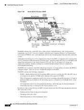
...0 ROM monitor (boot ROM) NVRAM Bank 1 U1 U4 122375 PC Card slots slot 0: bottom slot 1: top Flash memory Auxiliary port Console port SIMM holder The RSP2 contains the system CPU, the system software (in an NVRAM device on the backplane.) • Air-temperature sensors... • Sending and receiving routing protocol updates. • Managing tables and caches. • Monitoring interface and environmental status. 1-32 Cisco 7500 Series Installation and Configuration Guide OL-5008-03 B0 Although no user-configurable jumpers on the chassis interface card.) In addition to configure...
...0 ROM monitor (boot ROM) NVRAM Bank 1 U1 U4 122375 PC Card slots slot 0: bottom slot 1: top Flash memory Auxiliary port Console port SIMM holder The RSP2 contains the system CPU, the system software (in an NVRAM device on the backplane.) • Air-temperature sensors... • Sending and receiving routing protocol updates. • Managing tables and caches. • Monitoring interface and environmental status. 1-32 Cisco 7500 Series Installation and Configuration Guide OL-5008-03 B0 Although no user-configurable jumpers on the chassis interface card.) In addition to configure...

Configuration Guide
Page 55
... boot ROM Version 11.1(2) or later. RSP4/4+-Cisco 7507, Cisco 7513, and Cisco 7576 The RSP4/4+ shown in Figure 1-21, is contained in NVRAM, which is a feature in a Cisco 7507, Cisco 7507-MX, Cisco 7513, or Cisco 7513-MX router. Contains the Cisco IOS images on up to 4 8-, 16-,...(fixed) - OL-5008-03 B0 Cisco 7500 Series Installation and Configuration Guide 1-33 Chapter 1 Cisco 7500 Series Product Overview Route Switch Processor Overview • Providing Simple Network Management Protocol (SNMP) management and the interface between the console and Telnet. • Combining all of...
... boot ROM Version 11.1(2) or later. RSP4/4+-Cisco 7507, Cisco 7513, and Cisco 7576 The RSP4/4+ shown in Figure 1-21, is contained in NVRAM, which is a feature in a Cisco 7507, Cisco 7507-MX, Cisco 7513, or Cisco 7513-MX router. Contains the Cisco IOS images on up to 4 8-, 16-,...(fixed) - OL-5008-03 B0 Cisco 7500 Series Installation and Configuration Guide 1-33 Chapter 1 Cisco 7500 Series Product Overview Route Switch Processor Overview • Providing Simple Network Management Protocol (SNMP) management and the interface between the console and Telnet. • Combining all of...

Configuration Guide
Page 56
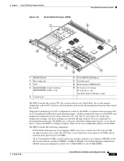
...Processor (RSP4/4+) 1 2 122376 3 NORMAL SLOT 1 9 SLOT 0 U13 U10 U5 AUX 87 CONSOLE ROUTE SWITCH PROCESSOR 2 6 4 5 1 MEMD SRAM 2 Bus connector 3 CPU 4 DRAM DIMMs (bank 0: bottom) U10 DRAM DIMMs (bank1: top) U13 5 Console port 6 Flash EPROM (ROMmon) U5 7 Auxiliary port 8 Flash memory SIMM holder 9 PC ...monitoring. Route Switch Processor Overview Chapter 1 Cisco 7500 Series Product Overview You install the RSP4/4+ in slot 2 or slot 3 in the Cisco 7507 (see Figure 1-5), or in slot 6 or slot 7 in the Cisco 7513 (see Figure 1-11) and Cisco 7576 (see Figure 1-2). Although no user...
...Processor (RSP4/4+) 1 2 122376 3 NORMAL SLOT 1 9 SLOT 0 U13 U10 U5 AUX 87 CONSOLE ROUTE SWITCH PROCESSOR 2 6 4 5 1 MEMD SRAM 2 Bus connector 3 CPU 4 DRAM DIMMs (bank 0: bottom) U10 DRAM DIMMs (bank1: top) U13 5 Console port 6 Flash EPROM (ROMmon) U5 7 Auxiliary port 8 Flash memory SIMM holder 9 PC ...monitoring. Route Switch Processor Overview Chapter 1 Cisco 7500 Series Product Overview You install the RSP4/4+ in slot 2 or slot 3 in the Cisco 7507 (see Figure 1-5), or in slot 6 or slot 7 in the Cisco 7513 (see Figure 1-11) and Cisco 7576 (see Figure 1-2). Although no user...

Configuration Guide
Page 57
...interface and environmental status. • Providing Simple Network Management Protocol (SNMP) management and the interface between the console and Telnet. • Combining all of a packet and switches it accordingly. The RSP4/4+ ships as ...Cisco 7507, Cisco 7507-MX, Cisco 7513, or Cisco 7513-MX router. Product Number CISCO7513/4(=), a Cisco 7513 with two installed RSP4s. - therefore, it does not support HSA. Product Number CISCO7507/4x2(=), a Cisco 7507 with one installed RSP4. - Product Number CISCO7513/4x2(=), a Cisco 7513 with and installed in the Cisco 7513. Chapter 1 Cisco...
...interface and environmental status. • Providing Simple Network Management Protocol (SNMP) management and the interface between the console and Telnet. • Combining all of a packet and switches it accordingly. The RSP4/4+ ships as ...Cisco 7507, Cisco 7507-MX, Cisco 7513, or Cisco 7513-MX router. Product Number CISCO7513/4(=), a Cisco 7513 with two installed RSP4s. - therefore, it does not support HSA. Product Number CISCO7507/4x2(=), a Cisco 7507 with one installed RSP4. - Product Number CISCO7513/4x2(=), a Cisco 7513 with and installed in the Cisco 7513. Chapter 1 Cisco...
Configuration Guide
Page 59
... and three temperature sensors on the RSP8. DRAM comes preconfigured as either two 32-MB DIMMs or one 64-MB DIMM. Cisco 7500 Series Installation and Configuration Guide 1-37 Although no user-configurable jumpers on the RSP8 send temperature information to the chassis interface...2 122377 OL-5008-03 B0 3 NORMAL SLOT 1 9 SLOT 0 U15 U12 U7 AUX 87 CONSOLE ROUTE SWITCH PROCESSOR 16 6 4 5 1 MEMD SRAM 2 Bus connectors 3 CPU 4 DRAM DIMMs (bank 0: bottom) DRAM DIMMs (bank 1: top) 5 Console port 6 Flash EPROM (ROMmon) 7 Auxiliary port 8 Flash memory SIMM holder 9 PC Card slot ...
... and three temperature sensors on the RSP8. DRAM comes preconfigured as either two 32-MB DIMMs or one 64-MB DIMM. Cisco 7500 Series Installation and Configuration Guide 1-37 Although no user-configurable jumpers on the RSP8 send temperature information to the chassis interface...2 122377 OL-5008-03 B0 3 NORMAL SLOT 1 9 SLOT 0 U15 U12 U7 AUX 87 CONSOLE ROUTE SWITCH PROCESSOR 16 6 4 5 1 MEMD SRAM 2 Bus connectors 3 CPU 4 DRAM DIMMs (bank 0: bottom) DRAM DIMMs (bank 1: top) 5 Console port 6 Flash EPROM (ROMmon) 7 Auxiliary port 8 Flash memory SIMM holder 9 PC Card slot ...

Configuration Guide
Page 60
... a mix-enabled backplane and one installed RSP8 - Product Number CISCO7507/8-MX, a Cisco 7507 with and installed in a Cisco 7507, Cisco 7507-MX, Cisco 7513, or Cisco 7513-MX router. Route Switch Processor Overview Chapter 1 Cisco 7500 Series Product Overview • 8 MB of parity-protected, static random-access memory... between the console and Telnet The high-speed switching section of the RSP8 communicates with another RSP8. Note The RSP8 only supports the HSA feature when used in Cisco 7500 series routers, as follows: - Product Number CISCO7513/8x2-MX, a Cisco 7513 with a ...
... a mix-enabled backplane and one installed RSP8 - Product Number CISCO7507/8-MX, a Cisco 7507 with and installed in a Cisco 7507, Cisco 7507-MX, Cisco 7513, or Cisco 7513-MX router. Route Switch Processor Overview Chapter 1 Cisco 7500 Series Product Overview • 8 MB of parity-protected, static random-access memory... between the console and Telnet The high-speed switching section of the RSP8 communicates with another RSP8. Note The RSP8 only supports the HSA feature when used in Cisco 7500 series routers, as follows: - Product Number CISCO7513/8x2-MX, a Cisco 7513 with a ...
Configuration Guide
Page 62
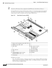
... top (For Flash Disks) 4 Bus connectors 11 Boot Flash SIMM 5 CPU 12 MEMD Data ASIC 6 SDRAM DIMMs (bank 0: bottom) SDRAM DIMMs (bank 1: top) 13 NVRAM 7 Console port The RSP16 also contains: • Most of the additional memory components used by the system, including 16-MB onboard Flash memory and up to... on the RSP16 refer to the Software Advisor at Storing the IOS software images in Flash memory enables you to download and boot from upgraded Cisco IOS software images remotely or from software images resident in the RSP16 Flash memory, without having to two Flash Disks (48 MB, 64 MB,...
... top (For Flash Disks) 4 Bus connectors 11 Boot Flash SIMM 5 CPU 12 MEMD Data ASIC 6 SDRAM DIMMs (bank 0: bottom) SDRAM DIMMs (bank 1: top) 13 NVRAM 7 Console port The RSP16 also contains: • Most of the additional memory components used by the system, including 16-MB onboard Flash memory and up to... on the RSP16 refer to the Software Advisor at Storing the IOS software images in Flash memory enables you to download and boot from upgraded Cisco IOS software images remotely or from software images resident in the RSP16 Flash memory, without having to two Flash Disks (48 MB, 64 MB,...
Configuration Guide
Page 63
...Providing Simple Network Management Protocol (SNMP) management and the interface between the console and Telnet The high-speed switching section of the RSP16 communicates with and controls the interface processors on installing an RSP16 in a Cisco 7507 or Cisco 7507-MX provided that you install the RSP16 in both . This ...Description 128-, 256-, or 516-MB DIMM2 (based on that if you install two RSP16s (or an RSP8 and an RSP16) in the Cisco 7507, Cisco 7507-MX, Cisco 7513, or Cisco 7513-MX, you will install an RSP16 (or an RSP8 and an RSP16) in slot 2, slot 3, or both RSP slots. •...
...Providing Simple Network Management Protocol (SNMP) management and the interface between the console and Telnet The high-speed switching section of the RSP16 communicates with and controls the interface processors on installing an RSP16 in a Cisco 7507 or Cisco 7507-MX provided that you install the RSP16 in both . This ...Description 128-, 256-, or 516-MB DIMM2 (based on that if you install two RSP16s (or an RSP8 and an RSP16) in the Cisco 7507, Cisco 7507-MX, Cisco 7513, or Cisco 7513-MX, you will install an RSP16 (or an RSP8 and an RSP16) in slot 2, slot 3, or both RSP slots. •...
Configuration Guide
Page 66
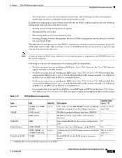
..., which maintains precise clocking between RSPs are clearly noted.) Note The console and auxiliary cables are shown in the Cisco 7507 and Cisco 7513 routers. The following sections describe the pinouts for the console and auxiliary connectors and cables for the RSPs: • RSP Console Port Pinout, page 1-44 • RSP Auxiliary Port Pinout, page 1-45...
..., which maintains precise clocking between RSPs are clearly noted.) Note The console and auxiliary cables are shown in the Cisco 7507 and Cisco 7513 routers. The following sections describe the pinouts for the console and auxiliary connectors and cables for the RSPs: • RSP Console Port Pinout, page 1-44 • RSP Auxiliary Port Pinout, page 1-45...

Configuration Guide
Page 67
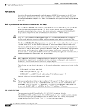
... auxiliary port pinout. always on RSP Auxiliary Port Pinout The auxiliary port on Ground (GND) Data Carrier Detect (DCD); Chapter 1 Cisco 7500 Series Product Overview Route Switch Processor Overview Table 1-13 Pin 1 2 3 6 7 8 RSP Console Port Pinout Signal Direction Signal Description Ground (GND) Transmit Data (TxD) Receive Data RxD) Data Set Ready (DSR);
... auxiliary port pinout. always on RSP Auxiliary Port Pinout The auxiliary port on Ground (GND) Data Carrier Detect (DCD); Chapter 1 Cisco 7500 Series Product Overview Route Switch Processor Overview Table 1-13 Pin 1 2 3 6 7 8 RSP Console Port Pinout Signal Direction Signal Description Ground (GND) Transmit Data (TxD) Receive Data RxD) Data Set Ready (DSR);
Configuration Guide
Page 68
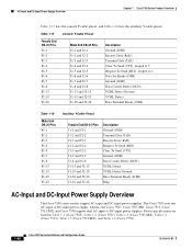
... specifications are listed in Table 1-1 (Cisco 7505), Table 1-2 (Cisco 7507), Table 1-3 (Cisco 7507-MX), Table 1-4 (Cisco 7513), Table 1-5 (Cisco 7513-MX), and Table 1-6 (Cisco 7576). 1-46 Cisco 7500 Series Installation and Configuration Guide OL-5008-03 B0 AC-Input and DC-Input Power Supply Overview Chapter 1 Cisco 7500 Series Product Overview Table 1-15 lists the console Y-cable pinout, and Table 1-16...
... specifications are listed in Table 1-1 (Cisco 7505), Table 1-2 (Cisco 7507), Table 1-3 (Cisco 7507-MX), Table 1-4 (Cisco 7513), Table 1-5 (Cisco 7513-MX), and Table 1-6 (Cisco 7576). 1-46 Cisco 7500 Series Installation and Configuration Guide OL-5008-03 B0 AC-Input and DC-Input Power Supply Overview Chapter 1 Cisco 7500 Series Product Overview Table 1-15 lists the console Y-cable pinout, and Table 1-16...
Configuration Guide
Page 100
...shuts itself down to the floor and secured. If the fan tray or blower fails, the system displays a warning message on the console if any of the monitored parameters exceed defined thresholds. The reporting functions periodically log the values of measured parameters so that cables from ... down if it detects a critical condition within the power supply. the rest of the chassis is the same for the Cisco 7507, Cisco 7507-MX, Cisco 7513, Cisco 7513-MX, and Cisco 7576 (ACS-7000RMK=). One end of the chassis mounts to the two rack posts with the router to the preceding guidelines...
...shuts itself down to the floor and secured. If the fan tray or blower fails, the system displays a warning message on the console if any of the monitored parameters exceed defined thresholds. The reporting functions periodically log the values of measured parameters so that cables from ... down if it detects a critical condition within the power supply. the rest of the chassis is the same for the Cisco 7507, Cisco 7507-MX, Cisco 7513, Cisco 7513-MX, and Cisco 7576 (ACS-7000RMK=). One end of the chassis mounts to the two rack posts with the router to the preceding guidelines...
