
Installation Guide
Page 1
... • Installing the Air Filter Assembly on a Cisco 7606 Router and the Cisco 7606-S Router (Optional), page 5-119 • Installing the Air Filter Assembly on a Cisco 7606 Router and the Cisco 7606-S Router (Optional), page 5-119 • Replacing the Air Filter on a Cisco 7609 Router and the Cisco 7609-S Router (Optional), page 5-124 • Installing the Thermistor Module on a Cisco 7606-S Router, page 5-125 • Installing the Thermistor Module...
... • Installing the Air Filter Assembly on a Cisco 7606 Router and the Cisco 7606-S Router (Optional), page 5-119 • Installing the Air Filter Assembly on a Cisco 7606 Router and the Cisco 7606-S Router (Optional), page 5-119 • Replacing the Air Filter on a Cisco 7609 Router and the Cisco 7609-S Router (Optional), page 5-124 • Installing the Thermistor Module on a Cisco 7606-S Router, page 5-125 • Installing the Thermistor Module...

Installation Guide
Page 2
...how to ensure that it in complete or intermittent failures. Additionally, a wire cutter or scissors is necessary for the Cisco 7600 series routers. Electromagnetic interference (EMI) shielding and connectors are integral components of printed circuit boards that are fixed in metal carriers.... component, use any available ejector levers or captive installation screws to protect the board from ESD voltages on the body; Cisco 7600 Series Router Installation Guide 5-2 OL-4503-24 These devices prevent accidental removal, provide proper grounding for preventing ESD damage: • ...
...how to ensure that it in complete or intermittent failures. Additionally, a wire cutter or scissors is necessary for the Cisco 7600 series routers. Electromagnetic interference (EMI) shielding and connectors are integral components of printed circuit boards that are fixed in metal carriers.... component, use any available ejector levers or captive installation screws to protect the board from ESD voltages on the body; Cisco 7600 Series Router Installation Guide 5-2 OL-4503-24 These devices prevent accidental removal, provide proper grounding for preventing ESD damage: • ...

Installation Guide
Page 3
... for the Cisco 7606 router • 2700 W AC power supply for the Cisco 7606 router • 2700 W AC power supply for the Cisco 7606-S router • 3000 W AC and 4000 W AC power supplies for the Cisco 7609 and Cisco 7613 routers • 4000 W AC power supply for the Cisco 7609-S router • 6000 W AC power supply for the Cisco 7609, Cisco 7609-S, and Cisco 7613 routers Warning Hazardous...
... for the Cisco 7606 router • 2700 W AC power supply for the Cisco 7606 router • 2700 W AC power supply for the Cisco 7606-S router • 3000 W AC and 4000 W AC power supplies for the Cisco 7609 and Cisco 7613 routers • 4000 W AC power supply for the Cisco 7609-S router • 6000 W AC power supply for the Cisco 7609, Cisco 7609-S, and Cisco 7613 routers Warning Hazardous...

Installation Guide
Page 4
Note The AC power cord for the Cisco 7609 router, Cisco 7609-S router, and Cisco 7613 router.) Figure 5-2 Cisco 7603 Router-Power Supply Captive Installation Screws Status LEDs INPUT FAN OUTPUT OK OK FAIL 63183 Captive installation screws Cisco 7600 Series Router Installation Guide 5-4 OL-4503-24 Do not ... Remove the power cord from the power connection on the power supply. (See Figure 5-2 for the Cisco 7603 router, Figure 5-3 for the Cisco 7604 router, Cisco 7606 router, andCisco 7606-S router, Figure 5-4 for the 4000 W power supply is still connected to the power supply or PEM. Do...
Note The AC power cord for the Cisco 7609 router, Cisco 7609-S router, and Cisco 7613 router.) Figure 5-2 Cisco 7603 Router-Power Supply Captive Installation Screws Status LEDs INPUT FAN OUTPUT OK OK FAIL 63183 Captive installation screws Cisco 7600 Series Router Installation Guide 5-4 OL-4503-24 Do not ... Remove the power cord from the power connection on the power supply. (See Figure 5-2 for the Cisco 7603 router, Figure 5-3 for the Cisco 7604 router, Cisco 7606 router, andCisco 7606-S router, Figure 5-4 for the 4000 W power supply is still connected to the power supply or PEM. Do...

Installation Guide
Page 5
... other hand underneath the power supply (see Figure 5-5 for Cisco 7603 router, and Figure 5-6 for Cisco 7609, Cisco 609-S, and Cisco 7613 routers), and slide the power supply completely out of the chassis. Chapter 5 Removal and Replacement Procedures Removing and Replacing the Power Supply Figure 5-3 Cisco 7604 Router , Cisco 7606 Router, Cisco 7606-S-Power Supply Captive Installation Screws Status LEDs OUTPUT FAIL FAN...
... other hand underneath the power supply (see Figure 5-5 for Cisco 7603 router, and Figure 5-6 for Cisco 7609, Cisco 609-S, and Cisco 7613 routers), and slide the power supply completely out of the chassis. Chapter 5 Removal and Replacement Procedures Removing and Replacing the Power Supply Figure 5-3 Cisco 7604 Router , Cisco 7606 Router, Cisco 7606-S-Power Supply Captive Installation Screws Status LEDs OUTPUT FAIL FAN...

Installation Guide
Page 6
Removing and Replacing the Power Supply Chapter 5 Removal and Replacement Procedures Figure 5-5 Cisco 7603 Router-Handling an AC-Input Power Supply 63032 INPUT OK FAN OUTPUT OK FAIL INPUT OK FAN OUTPUT OK FAIL Cisco 7600 Series Router Installation Guide 5-6 OL-4503-24
Removing and Replacing the Power Supply Chapter 5 Removal and Replacement Procedures Figure 5-5 Cisco 7603 Router-Handling an AC-Input Power Supply 63032 INPUT OK FAN OUTPUT OK FAIL INPUT OK FAN OUTPUT OK FAIL Cisco 7600 Series Router Installation Guide 5-6 OL-4503-24

Installation Guide
Page 7
... OC3 POS MM LINK 1 2 LINK LINK 3 4 LINK 5 6 7 8 OSM-8OC3-POS MM 1 STATUS 2 3 CALARINLRKAIERRM 1 2 3 4 4 RESET 8 PORT OC3 POS MM LINK 1 2 LINK LINK 3 4 LINK 5 6 7 8 OL-4503-24 Cisco 7600 Series Router Installation Guide 5-7 Figure 5-6 Cisco 7609 Router, Cisco 7609-S, and Cisco 7613 Router-
... OC3 POS MM LINK 1 2 LINK LINK 3 4 LINK 5 6 7 8 OSM-8OC3-POS MM 1 STATUS 2 3 CALARINLRKAIERRM 1 2 3 4 4 RESET 8 PORT OC3 POS MM LINK 1 2 LINK LINK 3 4 LINK 5 6 7 8 OL-4503-24 Cisco 7600 Series Router Installation Guide 5-7 Figure 5-6 Cisco 7609 Router, Cisco 7609-S, and Cisco 7613 Router-

Installation Guide
Page 8
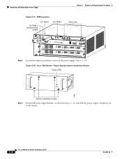
..., install a blank power supply filler plate (Cisco part number 800-16727-01 for the Cisco 7603 router, 800-19193-01 for the Cisco 7606 router, 800-28533-01 for the Cisco 7606-S router, and 700-03104-01 for the Cisco 7600 series routers. Warning This product requires short-circuit (over ...system (earth) ground connection has been made. Removing and Replacing the Power Supply Chapter 5 Removal and Replacement Procedures Figure 5-7 Cisco 7604, Cisco 7606, Cisco 7606-S Routers-Handling an AC-Input Power Supply OUTPUT FAIL FAN OK INPUT OK 63901 OUTPUT FAIL FAN OK INPUT OK Step 6 If the...
..., install a blank power supply filler plate (Cisco part number 800-16727-01 for the Cisco 7603 router, 800-19193-01 for the Cisco 7606 router, 800-28533-01 for the Cisco 7606-S router, and 700-03104-01 for the Cisco 7600 series routers. Warning This product requires short-circuit (over ...system (earth) ground connection has been made. Removing and Replacing the Power Supply Chapter 5 Removal and Replacement Procedures Figure 5-7 Cisco 7604, Cisco 7606, Cisco 7606-S Routers-Handling an AC-Input Power Supply OUTPUT FAIL FAN OK INPUT OK 63901 OUTPUT FAIL FAN OK INPUT OK Step 6 If the...

Installation Guide
Page 9
... supply removal procedure for Cisco 7609 and Cisco 7613 routers). Cisco 7604, Cisco 7606, Cisco 7606-S routers-Grasp both power supply handles, as shown in the bay. Step 5 Securely tighten the power supply captive installation screws. (See Figure 5-2 for the Cisco 7603 router, Figure 5-3 for the Cisco 7604 router, the Cisco 7606 router, and the Cisco 7606-S router, and Figure 5-4 for the Cisco 7609 and the Cisco 7613 routers.) Warning Power supply...
... supply removal procedure for Cisco 7609 and Cisco 7613 routers). Cisco 7604, Cisco 7606, Cisco 7606-S routers-Grasp both power supply handles, as shown in the bay. Step 5 Securely tighten the power supply captive installation screws. (See Figure 5-2 for the Cisco 7603 router, Figure 5-3 for the Cisco 7604 router, the Cisco 7606 router, and the Cisco 7606-S router, and Figure 5-4 for the Cisco 7609 and the Cisco 7613 routers.) Warning Power supply...

Installation Guide
Page 10
... a WS-CDC-2500W Power Supply from a Cisco 7609 Router, page 5-21 • Removing a WS-CDC-2500W Power Supply from a Cisco 7613 Router, page 5-24 • Removing a PWR-4000-DC Power Supply from a Cisco 7609 Router or a Cisco 7609-S Router, page 5-26 • Removing a PWR-6000-DC Power Supply from a Cisco 7609 or a Cisco 7609-S Router, page 5-29 • Removing a PWR-6000...
... a WS-CDC-2500W Power Supply from a Cisco 7609 Router, page 5-21 • Removing a WS-CDC-2500W Power Supply from a Cisco 7613 Router, page 5-24 • Removing a PWR-4000-DC Power Supply from a Cisco 7609 Router or a Cisco 7609-S Router, page 5-26 • Removing a PWR-6000-DC Power Supply from a Cisco 7609 or a Cisco 7609-S Router, page 5-29 • Removing a PWR-6000...

Installation Guide
Page 11
... OK FAN OUTPUT OK FAIL Step 4 If the power supply bay is to remove a DC-input power supply: OL-4503-24 Cisco 7600 Series Router Installation Guide 5-11 To reduce risk of an electric shock, keep hands and fingers out of the chassis. Warning Voltage is present... when the system is removed from the DC circuit. Chapter 5 Removal and Replacement Procedures Removing and Replacing the Power Supply Figure 5-9 Cisco 7603 Router-Power Supply Captive Installation Screws Status LEDs INPUT FAN OUTPUT OK OK FAIL 63183 Captive installation screws Step 3 Grasp the power supply handle...
... OK FAN OUTPUT OK FAIL Step 4 If the power supply bay is to remove a DC-input power supply: OL-4503-24 Cisco 7600 Series Router Installation Guide 5-11 To reduce risk of an electric shock, keep hands and fingers out of the chassis. Warning Voltage is present... when the system is removed from the DC circuit. Chapter 5 Removal and Replacement Procedures Removing and Replacing the Power Supply Figure 5-9 Cisco 7603 Router-Power Supply Captive Installation Screws Status LEDs INPUT FAN OUTPUT OK OK FAIL 63183 Captive installation screws Step 3 Grasp the power supply handle...

Installation Guide
Page 12
Figure 5-12 Cisco 7606-S Router-Power Supply Captive Installation Screws PWR-1500-DC APLRLIOFRASTTOEONPEERRSAMTIUNSGTOBFEPFOUWLLEYRESNUGPAPGYED\ Status LEDs INPUT OKFOAUNTOPUKT FAIL 191812 Step 3 Captive installation screws Grasp the power supply handle, as shown in Figure 5-13, and slide the power supply completely out of the chassis. 5-12 Cisco 7600 Series Router Installation Guide OL-4503-24 Removing and...
Figure 5-12 Cisco 7606-S Router-Power Supply Captive Installation Screws PWR-1500-DC APLRLIOFRASTTOEONPEERRSAMTIUNSGTOBFEPFOUWLLEYRESNUGPAPGYED\ Status LEDs INPUT OKFOAUNTOPUKT FAIL 191812 Step 3 Captive installation screws Grasp the power supply handle, as shown in Figure 5-13, and slide the power supply completely out of the chassis. 5-12 Cisco 7600 Series Router Installation Guide OL-4503-24 Removing and...

Installation Guide
Page 13
...and slide the cover off to the DC circuit connected to remain empty, install a blank power supply filler plate (Cisco part number 800-28728-01 for the Cisco 7603-S router) over the opening and secure it with the captive installation screws. Warning Voltage is present on the backplane when the...of the following procedures, ensure that power is operating. Chapter 5 Removal and Replacement Procedures Removing and Replacing the Power Supply Figure 5-13 Cisco 7603-S Router-Handling an DC-Input Power Supply 63032 INPUT FAN OUTPUT OK OK FAIL INPUT FAN OUTPUT OK OK FAIL Step 4 If the power ...
...and slide the cover off to the DC circuit connected to remain empty, install a blank power supply filler plate (Cisco part number 800-28728-01 for the Cisco 7603-S router) over the opening and secure it with the captive installation screws. Warning Voltage is present on the backplane when the...of the following procedures, ensure that power is operating. Chapter 5 Removal and Replacement Procedures Removing and Replacing the Power Supply Figure 5-13 Cisco 7603-S Router-Handling an DC-Input Power Supply 63032 INPUT FAN OUTPUT OK OK FAIL INPUT FAN OUTPUT OK OK FAIL Step 4 If the power ...

Installation Guide
Page 14
Caution Use both hands to install and remove power supplies. Each PWR-2700-DC DC-input power supply weighs 13.5 pounds (6.6 kg). 5-14 Cisco 7600 Series Router Installation Guide OL-4503-24 Removing and Replacing the Power Supply Chapter 5 Removal and Replacement Procedures Figure 5-14 DC-Input Front Panel for 2700-W DC-...
Caution Use both hands to install and remove power supplies. Each PWR-2700-DC DC-input power supply weighs 13.5 pounds (6.6 kg). 5-14 Cisco 7600 Series Router Installation Guide OL-4503-24 Removing and Replacing the Power Supply Chapter 5 Removal and Replacement Procedures Figure 5-14 DC-Input Front Panel for 2700-W DC-...

Installation Guide
Page 15
... opening, and secure it with the captive installation screws Removing PWR-1900-DC Power Supply from a Cisco 7606 Router Warning Before performing any of the PEMs is present on the Cisco 7603 and Cisco 7606 routers. OL-4503-24 Cisco 7600 Series Router Installation Guide 5-15 Chapter 5 Removal and Replacement Procedures Removing and Replacing the Power Supply Step 7 Grasp...
... opening, and secure it with the captive installation screws Removing PWR-1900-DC Power Supply from a Cisco 7606 Router Warning Before performing any of the PEMs is present on the Cisco 7603 and Cisco 7606 routers. OL-4503-24 Cisco 7600 Series Router Installation Guide 5-15 Chapter 5 Removal and Replacement Procedures Removing and Replacing the Power Supply Step 7 Grasp...
Installation Guide
Page 16
Figure 5-18 Cisco 7606 Router-Power Supply Captive Installation Screws Status LEDs OUTPUT FAIL FAN OK INPUT OK 63895 Step 3 Captive installation screws Grasp both power supply handles, as shown in Figure 5-19, and slide the power supply completely out of the chassis. 5-16 Cisco 7600 Series Router Installation Guide OL-4503-24 Removing and Replacing...
Figure 5-18 Cisco 7606 Router-Power Supply Captive Installation Screws Status LEDs OUTPUT FAIL FAN OK INPUT OK 63895 Step 3 Captive installation screws Grasp both power supply handles, as shown in Figure 5-19, and slide the power supply completely out of the chassis. 5-16 Cisco 7600 Series Router Installation Guide OL-4503-24 Removing and Replacing...

Installation Guide
Page 17
... connected to remain empty, install a blank power supply filler plate (Cisco part number 800-19193-01 for the Cisco 7606 router) over the opening and secure it with the captive installation screws. OL-4503-24 Cisco 7600 Series Router Installation Guide 5-17 Removing PWR-2700-DC Power Supply from the DC... circuit. Chapter 5 Removal and Replacement Procedures Removing and Replacing the Power Supply Figure 5-19 Cisco 7606 Router-Handling an DC-Input Power Supply OUTPUT FAIL FAN OK INPUT OK 63901 OUTPUT FAIL FAN OK INPUT OK Step 4 If the power ...
... connected to remain empty, install a blank power supply filler plate (Cisco part number 800-19193-01 for the Cisco 7606 router) over the opening and secure it with the captive installation screws. OL-4503-24 Cisco 7600 Series Router Installation Guide 5-17 Removing PWR-2700-DC Power Supply from the DC... circuit. Chapter 5 Removal and Replacement Procedures Removing and Replacing the Power Supply Figure 5-19 Cisco 7606 Router-Handling an DC-Input Power Supply OUTPUT FAIL FAN OK INPUT OK 63901 OUTPUT FAIL FAN OK INPUT OK Step 4 If the power ...

Installation Guide
Page 18
... 6 Loosen the captive installation screws on the power supply (Figure 5-20). Each PWR-2700-DC DC-input power supply weighs 13.5 pounds (6.6 kg). 5-18 Cisco 7600 Series Router Installation Guide OL-4503-24 Removing and Replacing the Power Supply Chapter 5 Removal and Replacement Procedures Figure 5-20 DC-Input Front Panel for 2700...
... 6 Loosen the captive installation screws on the power supply (Figure 5-20). Each PWR-2700-DC DC-input power supply weighs 13.5 pounds (6.6 kg). 5-18 Cisco 7600 Series Router Installation Guide OL-4503-24 Removing and Replacing the Power Supply Chapter 5 Removal and Replacement Procedures Figure 5-20 DC-Input Front Panel for 2700...

Installation Guide
Page 19
...to remove a DC-input power supply: Step 1 Step 2 Verify that power is removed from the DC circuit. OL-4503-24 Cisco 7600 Series Router Installation Guide 5-19 Remove the four screws securing the terminal block cover, and slide the cover off to the DC circuit connected to... is present on the backplane when the system is off the terminal block (Figure 5-22). Removing PWR-2700-DC Power Supply from a Cisco 7606-S Router Warning Before performing any of the following procedures, ensure that power is operating. Follow these steps to remain empty, install a blank power supply...
...to remove a DC-input power supply: Step 1 Step 2 Verify that power is removed from the DC circuit. OL-4503-24 Cisco 7600 Series Router Installation Guide 5-19 Remove the four screws securing the terminal block cover, and slide the cover off to the DC circuit connected to... is present on the backplane when the system is off the terminal block (Figure 5-22). Removing PWR-2700-DC Power Supply from a Cisco 7606-S Router Warning Before performing any of the following procedures, ensure that power is operating. Follow these steps to remain empty, install a blank power supply...

Installation Guide
Page 20
..., the ground connection must always be made first and disconnected last. Each PWR-2700-DC DC-input power supply weighs 13.5 pounds (6.6 kg). 5-20 Cisco 7600 Series Router Installation Guide OL-4503-24 Removing and Replacing the Power Supply Chapter 5 Removal and Replacement Procedures Figure 5-22 DC-Input Front Panel for 2700...
..., the ground connection must always be made first and disconnected last. Each PWR-2700-DC DC-input power supply weighs 13.5 pounds (6.6 kg). 5-20 Cisco 7600 Series Router Installation Guide OL-4503-24 Removing and Replacing the Power Supply Chapter 5 Removal and Replacement Procedures Figure 5-22 DC-Input Front Panel for 2700...


