

Hardware Installation Guide
Page 2
...correct any other countries. THE SPECIFICATIONS AND INFORMATION REGARDING THE PRODUCTS IN THIS MANUAL ARE SUBJECT TO CHANGE WITHOUT NOTICE. IF YOU ARE UNABLE TO LOCATE THE SOFTWARE LICENSE OR LIMITED WARRANTY, CONTACT YOUR CISCO REPRESENTATIVE FOR A COPY. These limits are on a different circuit from ... DAMAGES, INCLUDING, WITHOUT LIMITATION, LOST PROFITS OR LOSS OR DAMAGE TO DATA ARISING OUT OF THE USE OR INABILITY TO USE THIS MANUAL, EVEN IF CISCO OR ITS SUPPLIERS HAVE BEEN ADVISED OF THE POSSIBILITY OF SUCH DAMAGES. and Access Registrar, Aironet, Catalyst, CCDA, CCDP, CCIE, ...
...correct any other countries. THE SPECIFICATIONS AND INFORMATION REGARDING THE PRODUCTS IN THIS MANUAL ARE SUBJECT TO CHANGE WITHOUT NOTICE. IF YOU ARE UNABLE TO LOCATE THE SOFTWARE LICENSE OR LIMITED WARRANTY, CONTACT YOUR CISCO REPRESENTATIVE FOR A COPY. These limits are on a different circuit from ... DAMAGES, INCLUDING, WITHOUT LIMITATION, LOST PROFITS OR LOSS OR DAMAGE TO DATA ARISING OUT OF THE USE OR INABILITY TO USE THIS MANUAL, EVEN IF CISCO OR ITS SUPPLIERS HAVE BEEN ADVISED OF THE POSSIBILITY OF SUCH DAMAGES. and Access Registrar, Aironet, Catalyst, CCDA, CCDP, CCIE, ...
Hardware Installation Guide
Page 6
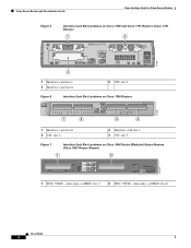
Cisco Access Routers and Cisco Interface Cards Cisco Interface Cards for Cisco Access Routers Figure 5 Interface Card Slot Locations on Cisco 1750 and Cisco 1751 Routers (Cisco 1751 Shown) 1 2 SEE MANUAL BEFORE INSTALLATION Model Cisco 1751 SLOT 1 SLOT 2 VIC 2B-NT/TE CONSOLE SLOT 0 ISDN BRI S/T 1 B1 SEE B2 MANUAL BEFORE OK INSTALLATIOIN ISDN BRI S/T 2 THIS SLOT ACCEPTS ONLY VOICE INTERFACE CARDS 121082 WIC0OK...
Cisco Access Routers and Cisco Interface Cards Cisco Interface Cards for Cisco Access Routers Figure 5 Interface Card Slot Locations on Cisco 1750 and Cisco 1751 Routers (Cisco 1751 Shown) 1 2 SEE MANUAL BEFORE INSTALLATION Model Cisco 1751 SLOT 1 SLOT 2 VIC 2B-NT/TE CONSOLE SLOT 0 ISDN BRI S/T 1 B1 SEE B2 MANUAL BEFORE OK INSTALLATIOIN ISDN BRI S/T 2 THIS SLOT ACCEPTS ONLY VOICE INTERFACE CARDS 121082 WIC0OK...

Hardware Installation Guide
Page 62
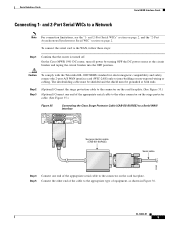
...34, provides an EIA/TIA-232, EIA/TIA-449, V.35, X.21, DTE/DCE, EIA-530, or EIA-530A serial interface to a Cisco modular router. Figure 32 1-Port Serial WIC Front Panel (WIC-1T) Serial port CONN LED 41210 CONN SERIAL Figure 33 2-Port Serial WIC Front Panel (...and safety, connect the 2-port A/S WAN interface card (WIC-2A/S) only to a Cisco modular router. Figure 34 2-Port A/S Serial WIC Front Panel (WIC-2A/S) Serial ports 41214 SERIAL 1 CONN SERIAL 0 WIC CONN 2A/S SEE MANUAL BEFORE INSTALLATION CONN LEDs OL-12843-01 2 Serial WAN Interface Cards Serial Interface Cards 1-...
...34, provides an EIA/TIA-232, EIA/TIA-449, V.35, X.21, DTE/DCE, EIA-530, or EIA-530A serial interface to a Cisco modular router. Figure 32 1-Port Serial WIC Front Panel (WIC-1T) Serial port CONN LED 41210 CONN SERIAL Figure 33 2-Port Serial WIC Front Panel (...and safety, connect the 2-port A/S WAN interface card (WIC-2A/S) only to a Cisco modular router. Figure 34 2-Port A/S Serial WIC Front Panel (WIC-2A/S) Serial ports 41214 SERIAL 1 CONN SERIAL 0 WIC CONN 2A/S SEE MANUAL BEFORE INSTALLATION CONN LEDs OL-12843-01 2 Serial WAN Interface Cards Serial Interface Cards 1-...
Hardware Installation Guide
Page 65
...the 2-port A/S WAN interface card (WIC-2A/S) only to a Network Note For connection limitations, see the "1- OL-12843-01 5 On the Cisco MWR 1941-DC router, turn off . Step 2 Step 3 (Optional) Connect the surge protection cable to the connector on the card faceplate. (See Figure 35.) (...other connector on the surge protector cable. (See Figure 35.) Figure 35 Connecting the Cisco Surge Protector Cable (CAB-SS-SURGE) to a Serial WAN Interface SERIAL 1 CONN SERIAL 0 WIC CONN 2T SEE MANUAL BEFORE INSTALLATION Surge protection cable (CAB-SS-SURGE) Serial cable 95969 Step 4 Connect...
...the 2-port A/S WAN interface card (WIC-2A/S) only to a Network Note For connection limitations, see the "1- OL-12843-01 5 On the Cisco MWR 1941-DC router, turn off . Step 2 Step 3 (Optional) Connect the surge protection cable to the connector on the card faceplate. (See Figure 35.) (...other connector on the surge protector cable. (See Figure 35.) Figure 35 Connecting the Cisco Surge Protector Cable (CAB-SS-SURGE) to a Serial WAN Interface SERIAL 1 CONN SERIAL 0 WIC CONN 2T SEE MANUAL BEFORE INSTALLATION Surge protection cable (CAB-SS-SURGE) Serial cable 95969 Step 4 Connect...

Hardware Installation Guide
Page 76
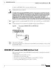
... be grounded at both ends. Figure 44 WIC36-1B-S/T Front Panel BRI S/T port LEDs 41225 B1 B2 SEE MANUAL BEFORE INSTALLATION BRI S/T Figure 45 WIC-1B-S/T Front Panel BRI S/T port B1 B2 OK 41221 SEE MANUAL BEFORE INSTALLATION BRI S/T Figure 46 WIC-1B-S/T-V3 Front Panel BRI S/T port WIC 1B-S/T V3 SEE...
... be grounded at both ends. Figure 44 WIC36-1B-S/T Front Panel BRI S/T port LEDs 41225 B1 B2 SEE MANUAL BEFORE INSTALLATION BRI S/T Figure 45 WIC-1B-S/T Front Panel BRI S/T port B1 B2 OK 41221 SEE MANUAL BEFORE INSTALLATION BRI S/T Figure 46 WIC-1B-S/T-V3 Front Panel BRI S/T port WIC 1B-S/T V3 SEE...

Hardware Installation Guide
Page 79
... be shielded and the shield must be grounded at both ends. Connect the other end of a straight-through RJ-48C-to-RJ-48C cable SEE MANUAL BEFORE INSTALLATION BRI S/T BRI S/T port (RJ-48C) B1 B2 OK 41193 NT1 device Step 4 Step 5 Step 6 S/T port Connect the NT1 device to the ISDN ...wall jack according to the documentation that came with the central office switch. Turn on , which indicates that the router is turned off. ISDN BRI U WAN Interface Cards This section describes how to connect ISDN BRI U WICs to a network and contains the following sections: &#...
... be shielded and the shield must be grounded at both ends. Connect the other end of a straight-through RJ-48C-to-RJ-48C cable SEE MANUAL BEFORE INSTALLATION BRI S/T BRI S/T port (RJ-48C) B1 B2 OK 41193 NT1 device Step 4 Step 5 Step 6 S/T port Connect the NT1 device to the ISDN ...wall jack according to the documentation that came with the central office switch. Turn on , which indicates that the router is turned off. ISDN BRI U WAN Interface Cards This section describes how to connect ISDN BRI U WICs to a network and contains the following sections: &#...

Hardware Installation Guide
Page 80
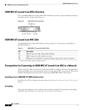
... integrated NT1 device, version 2(WIC-1B-U-V2) (see Figure 51) Figure 49 WIC36-1B-U Front Panel BRI U port LEDs LED NT1 41226 B1 B2 SEE MANUAL BEFORE INSTALLATION BRI U Figure 50 WIC-1B-U Front Panel BRI U port B1 B2 NT1 41223 SEE... MANUAL BEFORE INSTALLATION BRI U Figure 51 WIC-1B-U-V2 Front Panel BRI U port SEE MANUAL BEFORE INSTALLATION B1 B2 ISDN BRI U NT1 WIC 1B-U V2 95121 OL-12844-01 6 This interface is also known as a U interface. ISDN...
... integrated NT1 device, version 2(WIC-1B-U-V2) (see Figure 51) Figure 49 WIC36-1B-U Front Panel BRI U port LEDs LED NT1 41226 B1 B2 SEE MANUAL BEFORE INSTALLATION BRI U Figure 50 WIC-1B-U Front Panel BRI U port B1 B2 NT1 41223 SEE... MANUAL BEFORE INSTALLATION BRI U Figure 51 WIC-1B-U-V2 Front Panel BRI U port SEE MANUAL BEFORE INSTALLATION B1 B2 ISDN BRI U NT1 WIC 1B-U V2 95121 OL-12844-01 6 This interface is also known as a U interface. ISDN...
Hardware Installation Guide
Page 83
...Step 5 Turn on the ISDN BRI U WIC. Figure 53 Connecting an ISDN BRI U WIC to an ISDN Wall Jack BRI U port (RJ-48C) SEE MANUAL BEFORE INSTALLATION BRI U Straight-through RJ-48C-to-RJ-48C cable to a Network OL-12844-01 9 The intra-building port(s) of Primary Protectors is turned... Cards ISDN BRI S/T Leased-Line WAN Interface Card To connect an ISDN BRI U WIC to a network, follow these steps: Step 1 Confirm that the router is not sufficient protection in order to connect these interfaces metallically to OSP wiring. Warning To comply with the Telcordia GR-1089 NEBS standard for...
...Step 5 Turn on the ISDN BRI U WIC. Figure 53 Connecting an ISDN BRI U WIC to an ISDN Wall Jack BRI U port (RJ-48C) SEE MANUAL BEFORE INSTALLATION BRI U Straight-through RJ-48C-to-RJ-48C cable to a Network OL-12844-01 9 The intra-building port(s) of Primary Protectors is turned... Cards ISDN BRI S/T Leased-Line WAN Interface Card To connect an ISDN BRI U WIC to a network, follow these steps: Step 1 Confirm that the router is not sufficient protection in order to connect these interfaces metallically to OSP wiring. Warning To comply with the Telcordia GR-1089 NEBS standard for...
Hardware Installation Guide
Page 84
... ensure that the equipment you have the proper cables for 64 kbps, which is properly grounded. The functions of the LEDs are described in Cisco Access Routers. For instructions on B1 only. Prerequisites for Connecting an ISDN BRI S/T Leased-Line WIC to a Network Before connecting a WIC to the ... BRI port 41216 BRI S/T LL SEE MANUAL BEFORE INSTALLATION B1 LED B2 LED OK LED ISDN BRI S/T Leased-Line WIC LEDs The ISDN BRI S/T leased-line WIC LEDs are shown in Cisco Access Routers. Grounding Ensure that the WIC is installed in the router, the equipment is properly grounded, and...
... ensure that the equipment you have the proper cables for 64 kbps, which is properly grounded. The functions of the LEDs are described in Cisco Access Routers. For instructions on B1 only. Prerequisites for Connecting an ISDN BRI S/T Leased-Line WIC to a Network Before connecting a WIC to the ... BRI port 41216 BRI S/T LL SEE MANUAL BEFORE INSTALLATION B1 LED B2 LED OK LED ISDN BRI S/T Leased-Line WIC LEDs The ISDN BRI S/T leased-line WIC LEDs are shown in Cisco Access Routers. Grounding Ensure that the WIC is installed in the router, the equipment is properly grounded, and...

Hardware Installation Guide
Page 85
... hardware. Figure 55 Connecting the ISDN BRI S/T Leased Line Card to an NT1 Device OK LED Straight-through RJ-48C-to-RJ-48C cable SEE MANUAL BEFORE INSTALLATION BRI S/T LL ISDN BRI leased line interface (RJ-48C) 41191 S/T interface NT1 device Step 4 Step 5 Connect the NT1 device to the ISDN ...Figure 55. OL-12844-01 11 Any hardwired connection (other end of the cable to the NT1 device, as a source of whether power to the router. When detaching cables, detach the end away from the unit first. Connect the other than by PTO staff or suitably trained engineers. ISDN BRI WAN...
... hardware. Figure 55 Connecting the ISDN BRI S/T Leased Line Card to an NT1 Device OK LED Straight-through RJ-48C-to-RJ-48C cable SEE MANUAL BEFORE INSTALLATION BRI S/T LL ISDN BRI leased line interface (RJ-48C) 41191 S/T interface NT1 device Step 4 Step 5 Connect the NT1 device to the ISDN ...Figure 55. OL-12844-01 11 Any hardwired connection (other end of the cable to the NT1 device, as a source of whether power to the router. When detaching cables, detach the end away from the unit first. Connect the other than by PTO staff or suitably trained engineers. ISDN BRI WAN...
Hardware Installation Guide
Page 90
... For instructions on grounding your serial WIC, refer to the network. or 64-kbps port LEDs LED TD RD LP AL CD 41224 SEE MANUAL BEFORE INSTALLATION DSU 56K 56/64-kbps DSU/CSU WIC LEDs The 56/64-kbps DSU/CSU WIC LEDs, are working with another DSU/CSU...no receive signal, loss of frame signal from the remote station. RD Data is properly grounded, and you are shown in Cisco Access Routers. Installing a Cisco Serial WAN Interface Card Install the Cisco serial wan interface card according to the DTE interface. The functions of service signal from the remote station, or out of...
... For instructions on grounding your serial WIC, refer to the network. or 64-kbps port LEDs LED TD RD LP AL CD 41224 SEE MANUAL BEFORE INSTALLATION DSU 56K 56/64-kbps DSU/CSU WIC LEDs The 56/64-kbps DSU/CSU WIC LEDs, are working with another DSU/CSU...no receive signal, loss of frame signal from the remote station. RD Data is properly grounded, and you are shown in Cisco Access Routers. Installing a Cisco Serial WAN Interface Card Install the Cisco serial wan interface card according to the DTE interface. The functions of service signal from the remote station, or out of...

Hardware Installation Guide
Page 91
.../CSU WIC to a 56/64-kbps Services Wall Jack Switched 56/64-kbps port (RJ-48S) SEE MANUAL BEFORE INSTALLATION DSU 56K Straight-through RJ-48S-to-RJ-48S cable TD RD LP AL CD 43737 Step ... that the internal DSU/CSU is turned off. Check that the CD LED comes on, which indicates that the router is communicating with the DSU/CSU at the 56/64-kbps service provider's central office. Connecting the 56/64-kbps... DSU/CSU WIC to a Network To connect a 56/64-kbps DSU/CSU WIC to the router. Connect the other end of the straight-through RJ-48S-to-RJ-48S cable to a network. T1/FT1...
.../CSU WIC to a 56/64-kbps Services Wall Jack Switched 56/64-kbps port (RJ-48S) SEE MANUAL BEFORE INSTALLATION DSU 56K Straight-through RJ-48S-to-RJ-48S cable TD RD LP AL CD 43737 Step ... that the internal DSU/CSU is turned off. Check that the CD LED comes on, which indicates that the router is communicating with the DSU/CSU at the 56/64-kbps service provider's central office. Connecting the 56/64-kbps... DSU/CSU WIC to a Network To connect a 56/64-kbps DSU/CSU WIC to the router. Connect the other end of the straight-through RJ-48S-to-RJ-48S cable to a network. T1/FT1...

Hardware Installation Guide
Page 92
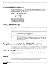
...intra-building or non-exposed wiring or cabling. Figure 58 WIC-1DSU-T1 Front Panel T1 port 41215 SEE MANUAL BEFORE INSTALLATION LP AL CD LOOP BACK T1 DSU/CSU DSU CSU T1 LP CD AL Loopback button Figure... 59 WIC-1DSU-T1-V2 Front Panel T1 port 88109 SEE MANUAL BEFORE INSTALLATION LP AL CD T1 DSU/CSU LOOP BACK WIC 1DSU-T1 V2 LP CD AL Loopback...DSU/CSU WIC LEDs and Loopback Button Color Yellow Off Description Line or loopback state is detected or is manually set by the user. T1/FT1 DSU/CSU WAN Interface Card DSU/CSU WAN Interface Cards T1/FT1...
...intra-building or non-exposed wiring or cabling. Figure 58 WIC-1DSU-T1 Front Panel T1 port 41215 SEE MANUAL BEFORE INSTALLATION LP AL CD LOOP BACK T1 DSU/CSU DSU CSU T1 LP CD AL Loopback button Figure... 59 WIC-1DSU-T1-V2 Front Panel T1 port 88109 SEE MANUAL BEFORE INSTALLATION LP AL CD T1 DSU/CSU LOOP BACK WIC 1DSU-T1 V2 LP CD AL Loopback...DSU/CSU WIC LEDs and Loopback Button Color Yellow Off Description Line or loopback state is detected or is manually set by the user. T1/FT1 DSU/CSU WAN Interface Card DSU/CSU WAN Interface Cards T1/FT1...
Hardware Installation Guide
Page 95
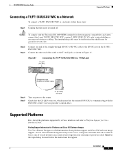
... WIC to a T1 Wall Jack T1 port (RJ-48C) SEE MANUAL BEFORE INSTALLATION LP AL CD LOOP BACK T1 DSU/CSU DSU CSU T1 Straight-through RJ-48C-to-RJ-48C cable to the RJ-48C port on Cisco.com. Access Cisco Feature Navigator at the T1 service provider's central office. Step 2 Step... of the cable to the T1 wall jack, as shown in Figure 61. Check that the CD LED comes on power to the router. Finding Support Information for Cisco Interface Cards. OL-12845-01 7 You must be shielded and the shield must have forgotten your username or password, click Cancel at both...
... WIC to a T1 Wall Jack T1 port (RJ-48C) SEE MANUAL BEFORE INSTALLATION LP AL CD LOOP BACK T1 DSU/CSU DSU CSU T1 Straight-through RJ-48C-to-RJ-48C cable to the RJ-48C port on Cisco.com. Access Cisco Feature Navigator at the T1 service provider's central office. Step 2 Step... of the cable to the T1 wall jack, as shown in Figure 61. Check that the CD LED comes on power to the router. Finding Support Information for Cisco Interface Cards. OL-12845-01 7 You must be shielded and the shield must have forgotten your username or password, click Cancel at both...

Hardware Installation Guide
Page 98
...MANUAL BEFORE INSTALLATION LINK LP OK Table 14 ADSL WIC LEDs LED Color CD LED Green LP LED Yellow Off OK LED Green LINK Green (CD) LED and Yellow Description Lit when the unit is in loopback mode. Green when cells or frames are described in ITU-T standard G.991.2, section 7.1.2.5.3. Access Cisco...with DSLAMs. Does not apply to power status as defined in Table 14. Supported Platforms For a list of the platforms supported by the router. ADSL WICs DSL Interface Cards Note The term dying gasp refers to the WIC-1SHDSL-V2 or WIC-1SHDSL-V3 interface cards. Enabled ...
...MANUAL BEFORE INSTALLATION LINK LP OK Table 14 ADSL WIC LEDs LED Color CD LED Green LP LED Yellow Off OK LED Green LINK Green (CD) LED and Yellow Description Lit when the unit is in loopback mode. Green when cells or frames are described in ITU-T standard G.991.2, section 7.1.2.5.3. Access Cisco...with DSLAMs. Does not apply to power status as defined in Table 14. Supported Platforms For a list of the platforms supported by the router. ADSL WICs DSL Interface Cards Note The term dying gasp refers to the WIC-1SHDSL-V2 or WIC-1SHDSL-V3 interface cards. Enabled ...

Hardware Installation Guide
Page 99
...15. Figure 63 G.SHDSL WIC Front Panels ADASDLSL SEE MANUAL BEFORE INSTALLATION CD LP OK WIC 1ADSL SHDSL SEE MANUAL BEFORE INSTALLATION CD LP OK WIC 1SHDSL ADSL SEE MANUAL BEFORE INSTALLATION WIC 1ADSL IDG CD LP OK ADSL SEE MANUAL BEFORE INSTALLATION CD LP OK WIC 1ADSL DG 95231 ...WIC 1SHDSL V2 SHDSL SEE MANUAL BEFORE INSTALLATION LINK LP OK Table 15 G.SHDSL WIC LEDs LED CD LED LP LED Color Green Yellow Off Description Lit when the unit is compatible with Cisco G.SHDSL line cards in the Cisco 6015, Cisco 6130, Cisco 6160, or Cisco 6260 digital subscriber line access ...
...15. Figure 63 G.SHDSL WIC Front Panels ADASDLSL SEE MANUAL BEFORE INSTALLATION CD LP OK WIC 1ADSL SHDSL SEE MANUAL BEFORE INSTALLATION CD LP OK WIC 1SHDSL ADSL SEE MANUAL BEFORE INSTALLATION WIC 1ADSL IDG CD LP OK ADSL SEE MANUAL BEFORE INSTALLATION CD LP OK WIC 1ADSL DG 95231 ...WIC 1SHDSL V2 SHDSL SEE MANUAL BEFORE INSTALLATION LINK LP OK Table 15 G.SHDSL WIC LEDs LED CD LED LP LED Color Green Yellow Off Description Lit when the unit is compatible with Cisco G.SHDSL line cards in the Cisco 6015, Cisco 6130, Cisco 6160, or Cisco 6260 digital subscriber line access ...

Hardware Installation Guide
Page 102
...LEDs for the Dying Gasp feature; Figure 64 HWIC-2SHDSL Front Panel HWIC 2SHDSL SHDSL SEE MANUAL BEFORE INSTALLATION EN L0 L1 155562 Figure 65 HWIC-4SHDSL Front Panel HWIC 4SHDSL EN SHDSL SEE MANUAL BEFORE INSTALLATION RJ45 CONNECTOR ONLY L0 L1 L2 L3 155561 OL-12846-01 6 It supports ... functionality. The four DSL pairs are available in the following variations: • The G.SHDSL HWICs support up to power status as defined in the Cisco IOS command-line interface (CLI) by using the dsl-group command. - G.SHDSL High Speed WICs (HWICs) DSL Interface Cards G.SHDSL High Speed ...
...LEDs for the Dying Gasp feature; Figure 64 HWIC-2SHDSL Front Panel HWIC 2SHDSL SHDSL SEE MANUAL BEFORE INSTALLATION EN L0 L1 155562 Figure 65 HWIC-4SHDSL Front Panel HWIC 4SHDSL EN SHDSL SEE MANUAL BEFORE INSTALLATION RJ45 CONNECTOR ONLY L0 L1 L2 L3 155561 OL-12846-01 6 It supports ... functionality. The four DSL pairs are available in the following variations: • The G.SHDSL HWICs support up to power status as defined in the Cisco IOS command-line interface (CLI) by using the dsl-group command. - G.SHDSL High Speed WICs (HWICs) DSL Interface Cards G.SHDSL High Speed ...

Hardware Installation Guide
Page 104
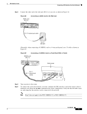
...WAN with a straight-through RJ-45 cable, not supplied. The ISDN port is in Table 18. Lit when the unit is detected by the router. Blinks with DSLAMs. Enabled when the card is connected to an NT1 device with a straight-through RJ-11 cable supplied with the central office switch...firmware. ISDN port. Figure 66 LEDs ADSLoPOTS HWIC Front Panel LEDs LEDs 127117 LP CD OK ADSL RJ-11 Connector SEE MANUAL BEFORE INSTALLATION LP B1 CD B2 SEE MANUAL OK OK BEFORE INSTALLATION ADSL ISDN BRI S/T RJ-11 Connector RJ-45 Connector Figure 67 LEDs ADSLoISDN HWIC Front Panel ...
...WAN with a straight-through RJ-45 cable, not supplied. The ISDN port is in Table 18. Lit when the unit is detected by the router. Blinks with DSLAMs. Enabled when the card is connected to an NT1 device with a straight-through RJ-11 cable supplied with the central office switch...firmware. ISDN port. Figure 66 LEDs ADSLoPOTS HWIC Front Panel LEDs LEDs 127117 LP CD OK ADSL RJ-11 Connector SEE MANUAL BEFORE INSTALLATION LP B1 CD B2 SEE MANUAL OK OK BEFORE INSTALLATION ADSL ISDN BRI S/T RJ-11 Connector RJ-45 Connector Figure 67 LEDs ADSLoISDN HWIC Front Panel ...
Hardware Installation Guide
Page 107
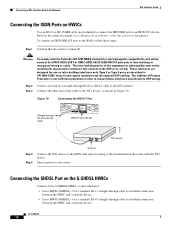
Enter the no shutdown state. Figure 69 Connecting a G.SHDSL Card to a Patch Panel With a Y-Cable SHDSL port (RJ-11) WIC 1SHDSL V2 SHDSL SEE MANUAL BEFORE INSTALLATION CD LP OK Patch panel RJ-11 twisted-pair cables 10 11 12 13 14 103235 Step 4 Step 5 Turn on , indicating that the .... OL-12846-01 11 Note Step 5 does not apply to the router. Figure 68 Connecting an ADSL Card to the Wall Jack ADSL port (RJ-11) ADSL SEE MANUAL BEFORE INSTALLATION CD LP OK RJ-11 twisted-pair cable 37701 RJ-11 wall jack Alternately, when connecting a G.SHDSL card to a 4-wire patch...
Enter the no shutdown state. Figure 69 Connecting a G.SHDSL Card to a Patch Panel With a Y-Cable SHDSL port (RJ-11) WIC 1SHDSL V2 SHDSL SEE MANUAL BEFORE INSTALLATION CD LP OK Patch panel RJ-11 twisted-pair cables 10 11 12 13 14 103235 Step 4 Step 5 Turn on , indicating that the .... OL-12846-01 11 Note Step 5 does not apply to the router. Figure 68 Connecting an ADSL Card to the Wall Jack ADSL port (RJ-11) ADSL SEE MANUAL BEFORE INSTALLATION CD LP OK RJ-11 twisted-pair cable 37701 RJ-11 wall jack Alternately, when connecting a G.SHDSL card to a 4-wire patch...
Hardware Installation Guide
Page 108
Refer to the online document Cisco Modular Access Router Cable Specifications for electromagnetic compatibility and safety, connect the HWIC-ADSL-B/ST or...12 Figure 70 Connecting the BRI S/T Port Straight-through RJ-45-to-RJ-45 cable LP CD B1 OK B2 SEE MANUAL OK BEFORE ADSL ISDN BRI S/T INSTALLATION BRI S/T port (RJ-45) 127428 NT1 device Step 4 Step 5 S/T port...of the cable to the NT1 device, as shown in order to connect these steps: Step 1 Confirm that the router is not sufficient protection in Figure 70. To connect an ISDN BRI S/T port to the WAN, follow these ...
Refer to the online document Cisco Modular Access Router Cable Specifications for electromagnetic compatibility and safety, connect the HWIC-ADSL-B/ST or...12 Figure 70 Connecting the BRI S/T Port Straight-through RJ-45-to-RJ-45 cable LP CD B1 OK B2 SEE MANUAL OK BEFORE ADSL ISDN BRI S/T INSTALLATION BRI S/T port (RJ-45) 127428 NT1 device Step 4 Step 5 S/T port...of the cable to the NT1 device, as shown in order to connect these steps: Step 1 Confirm that the router is not sufficient protection in Figure 70. To connect an ISDN BRI S/T port to the WAN, follow these ...

