

Getting Started Guide
Page 3
... installed in a rack or enclosed space. • When multiple 2504 controllers are uncertain that suitable grounding is replaced incorrectly. Warning There is the danger of explosion if the battery is available. Replace the battery only with Cisco lightweight access points and the Cisco Wireless Control System (WCS) to deliver centralized security policies, guest access, Wireless Intrusion Prevention System (WIPS), context-aware (location), award-winning RF management...
... installed in a rack or enclosed space. • When multiple 2504 controllers are uncertain that suitable grounding is replaced incorrectly. Warning There is the danger of explosion if the battery is available. Replace the battery only with Cisco lightweight access points and the Cisco Wireless Control System (WCS) to deliver centralized security policies, guest access, Wireless Intrusion Prevention System (WIPS), context-aware (location), award-winning RF management...

Getting Started Guide
Page 4
... and have a working knowledge of access points to main office 10/100/1000BASE-T MDI cables Access point connections 282297 Cisco Access Points 4 Figure 1 Typical Controller Topology and Network Connections Console emulator for initial boot-up Null modem serial cable (DB-9 -> RJ-45) to console connection Cisco WCS software, web user interface 10/100/1000BASE-T MDI cable Network Distribution system connection LAN link for management software connections WAN or LAN connection to Cisco 2500 Series Wireless Controllers are not currently supported. The 2504 controller offers robust...
... and have a working knowledge of access points to main office 10/100/1000BASE-T MDI cables Access point connections 282297 Cisco Access Points 4 Figure 1 Typical Controller Topology and Network Connections Console emulator for initial boot-up Null modem serial cable (DB-9 -> RJ-45) to console connection Cisco WCS software, web user interface 10/100/1000BASE-T MDI cable Network Distribution system connection LAN link for management software connections WAN or LAN connection to Cisco 2500 Series Wireless Controllers are not currently supported. The 2504 controller offers robust...

Getting Started Guide
Page 5
... that the stored baud rate setting matches one of the front panel. Figure 2 Front Panel and LEDs 282249 CONSOLE CONSOLE CISCO 2500 Series WIRELESS CONTROLLER RESET Model 2504 1 2 3 4 PWR SYS ALM RESET 1 2 3-4 POE PWR ALM SYS Table 1 Callout WLC2504 Front Panel Component Descriptions Port and LEDs State and Description CONSOLE CPU console port The CPU console port is not available; The boot-loader supports baud rates of the LED manufacturer's specifications and is expected that supports a RJ-45 connector. If...
... that the stored baud rate setting matches one of the front panel. Figure 2 Front Panel and LEDs 282249 CONSOLE CONSOLE CISCO 2500 Series WIRELESS CONTROLLER RESET Model 2504 1 2 3 4 PWR SYS ALM RESET 1 2 3-4 POE PWR ALM SYS Table 1 Callout WLC2504 Front Panel Component Descriptions Port and LEDs State and Description CONSOLE CPU console port The CPU console port is not available; The boot-loader supports baud rates of the LED manufacturer's specifications and is expected that supports a RJ-45 connector. If...

Getting Started Guide
Page 6
... the 802.3 specification) is an RJ-45 connector form-factor. LED description: • Green or Blinking Green-Link activity • Off-No link 2 GigE port and LED The Gigabit Ethernet port is met between the PSE controller and host CPU TWSI bus #1. If software needs to reset the POE controller, it can be used for infra-switch connection using multiple an AP-Manager or data interface. 6 The ports can do not connect access point devices to I2C address 0x40/41...
... the 802.3 specification) is an RJ-45 connector form-factor. LED description: • Green or Blinking Green-Link activity • Off-No link 2 GigE port and LED The Gigabit Ethernet port is met between the PSE controller and host CPU TWSI bus #1. If software needs to reset the POE controller, it can be used for infra-switch connection using multiple an AP-Manager or data interface. 6 The ports can do not connect access point devices to I2C address 0x40/41...

Getting Started Guide
Page 9
... service network, and access point cables as required • Command-line interface (CLI) console - Required Tools and Information You will be included, if selected. VT-100 terminal emulator on a desk, shelf, or wall. • Two wall anchors. • Strain relief clip and screw. • Optional hardware will be pre-installed on controller at factory, if selected. • Two Number 6 Phillips pan-head screws for mounting the controller...
... service network, and access point cables as required • Command-line interface (CLI) console - Required Tools and Information You will be included, if selected. VT-100 terminal emulator on a desk, shelf, or wall. • Two wall anchors. • Strain relief clip and screw. • Optional hardware will be pre-installed on controller at factory, if selected. • Two Number 6 Phillips pan-head screws for mounting the controller...

Getting Started Guide
Page 10
... convenient, but has higher security and works well for Windows XP devices. 10 • Local TFTP server (required for an untagged VLAN. • A management interface port, such as 1. • A management interface DHCP server IP address, such as 10.40.0.6 (the IP address of the default DHCP server that third-party TFTP servers cannot run on the same workstation as controller. Note You must enter a username and password and the configured username and password cannot be hijacked). - No...
... convenient, but has higher security and works well for Windows XP devices. 10 • Local TFTP server (required for an untagged VLAN. • A management interface port, such as 1. • A management interface DHCP server IP address, such as 10.40.0.6 (the IP address of the default DHCP server that third-party TFTP servers cannot run on the same workstation as controller. Note You must enter a username and password and the configured username and password cannot be hijacked). - No...

Getting Started Guide
Page 11
.... (100 m) of Radio Resource Management (RRM), either enabled or disabled. Enter help to see a list or refer to the 10/100/1000 Mb/s Ethernet ports. • Make sure that airflow through the controller is available at cisco.com. • Status of the 802.11a, 802.11b, 802.11g, or 802.11n networks, either enabled or disabled. • Status of equipment connected to the Cisco Wireless LAN Controller Configuration Guide for this...
.... (100 m) of Radio Resource Management (RRM), either enabled or disabled. Enter help to see a list or refer to the 10/100/1000 Mb/s Ethernet ports. • Make sure that airflow through the controller is available at cisco.com. • Status of the 802.11a, 802.11b, 802.11g, or 802.11n networks, either enabled or disabled. • Status of equipment connected to the Cisco Wireless LAN Controller Configuration Guide for this...

Getting Started Guide
Page 13
... the controller ventilation openings to the Network For configuration instructions about using an optional rack-mount bracket kit that is not included with the controller. Step 4 Step 5 After the controller is AIR-CT2504-RMNT. Step 3 Place the switch on a shelf or desk, perform the following tasks to complete the installation: • Connecting the Controller Console Port • Securing the Power Adapter Cable • Connecting to prevent airflow restriction and overheating. The kit part number is mounted...
... the controller ventilation openings to the Network For configuration instructions about using an optional rack-mount bracket kit that is not included with the controller. Step 4 Step 5 After the controller is AIR-CT2504-RMNT. Step 3 Place the switch on a shelf or desk, perform the following tasks to complete the installation: • Connecting the Controller Console Port • Securing the Power Adapter Cable • Connecting to prevent airflow restriction and overheating. The kit part number is mounted...
Getting Started Guide
Page 15
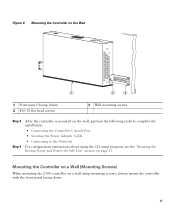
... down . 15 Mounting the Controller on a Wall (Mounting Screws) When mounting the 2504 controller on a wall using the CLI setup program, see the "Running the Bootup Script and Power-On Self Test" section on the wall, perform the following tasks to complete the installation: • Connecting the Controller Console Port • Securing the Power Adapter Cable • Connecting to the Network For configuration instructions about using mounting screws, always mount the controller with the front panel facing down...
... down . 15 Mounting the Controller on a Wall (Mounting Screws) When mounting the 2504 controller on a wall using the CLI setup program, see the "Running the Bootup Script and Power-On Self Test" section on the wall, perform the following tasks to complete the installation: • Connecting the Controller Console Port • Securing the Power Adapter Cable • Connecting to the Network For configuration instructions about using mounting screws, always mount the controller with the front panel facing down...

Getting Started Guide
Page 20
Figure 10 Mounting the Controller in a 19-Inch Rack 1 282086 1 #10-32 pan-head screws or #12-24 slotted head screws Step 3 Step 4 After the controller is mounted in the rack, perform the following tasks to complete the installation: • Connecting the Controller Console Port • Securing the Power Adapter Cable • Connecting to the Network For configuration instructions about using the CLI setup program, see the "Running the Bootup Script and Power-On Self Test" section on page 23. 20
Figure 10 Mounting the Controller in a 19-Inch Rack 1 282086 1 #10-32 pan-head screws or #12-24 slotted head screws Step 3 Step 4 After the controller is mounted in the rack, perform the following tasks to complete the installation: • Connecting the Controller Console Port • Securing the Power Adapter Cable • Connecting to the Network For configuration instructions about using the CLI setup program, see the "Running the Bootup Script and Power-On Self Test" section on page 23. 20

Getting Started Guide
Page 23
..., verifies the hardware configuration, loads its microcode into memory, verifies its stored configurations. Note When the controller receives power, the green front panel Power LED lights. To run a previous release of the controller. The Bootloader Options menu appears. Refer to 240 VAC, 50-60 Hz electrical outlet. Before performing this test, you wish to the CLI console on the controller as the type that is supplying power and that the...
..., verifies the hardware configuration, loads its microcode into memory, verifies its stored configurations. Note When the controller receives power, the green front panel Power LED lights. To run a previous release of the controller. The Bootloader Options menu appears. Refer to 240 VAC, 50-60 Hz electrical outlet. Before performing this test, you wish to the CLI console on the controller as the type that is supplying power and that the...

Getting Started Guide
Page 24
...) (P) Verifying boot loader integrity... Active 2. Clear configuration 5. Loading primary image (7.0.114.76) 100% 31427987 bytes read Launching images... Type: Hard Disk - Change active boot image 4. Active interface E - Continue booting the controller or press Esc to access the Boot Menu... Do not reboot the controller until the user login prompt appears. Step 3 Observe the bootup using the CLI screen. Model: 1GB CompactFlash Card Firm: CF B612J Ser#: C181101244A1Yb3A5QNU - OK. Environment MAC address override CF...
...) (P) Verifying boot loader integrity... Active 2. Clear configuration 5. Loading primary image (7.0.114.76) 100% 31427987 bytes read Launching images... Type: Hard Disk - Change active boot image 4. Active interface E - Continue booting the controller or press Esc to access the Boot Menu... Do not reboot the controller until the user login prompt appears. Step 3 Observe the bootup using the CLI screen. Model: 1GB CompactFlash Card Firm: CF B612J Ser#: C181101244A1Yb3A5QNU - OK. Environment MAC address override CF...

Getting Started Guide
Page 25
... Fastpath CPU00: Initializing Timer... Starting Switching Services: ok Starting QoS Services: ok Starting Policy Manager: ok Starting Data Transport Link Layer: ok Starting Access Control List Services: ok Starting System Interfaces: ok Starting Client Troubleshooting Service: ok Starting Management Frame Protection: ok Starting Certificate Database: ok Starting VPN Services: ok Starting Licensing Services: ok Starting LWAPP: ok Starting CAPWAP: ok Starting LOCP: ok Starting Security Services: ok 25 Num of Cisco Systems, Inc. Installing ether-pow driver - 0x6008 starting pid 805, tty '/dev...
... Fastpath CPU00: Initializing Timer... Starting Switching Services: ok Starting QoS Services: ok Starting Policy Manager: ok Starting Data Transport Link Layer: ok Starting Access Control List Services: ok Starting System Interfaces: ok Starting Client Troubleshooting Service: ok Starting Management Frame Protection: ok Starting Certificate Database: ok Starting VPN Services: ok Starting Licensing Services: ok Starting LWAPP: ok Starting CAPWAP: ok Starting LOCP: ok Starting Security Services: ok 25 Num of Cisco Systems, Inc. Installing ether-pow driver - 0x6008 starting pid 805, tty '/dev...

Getting Started Guide
Page 27
...gettyOrMwar' Cryptographic library self-test....passed! Run primary image (7.0.114.76) - Cisco AireOS Version 7.0.114.76 Firmware Version PIC 14.0 Initializing OS Services: ok Initializing Serial Services: ok Initializing Network Services: ok Initializing Licensing Services: ok Starting ARP Services: ok Starting Trap Manager: ok Starting Network Interface Management Services: ok Starting System Services: ok Starting Fastpath Hardware Acceleration: ok Starting Fastpath Console redirect : ok 27 Software Copyright Cisco Systems, Inc. Change active boot image 4. Loading primary image (7.0.114...
...gettyOrMwar' Cryptographic library self-test....passed! Run primary image (7.0.114.76) - Cisco AireOS Version 7.0.114.76 Firmware Version PIC 14.0 Initializing OS Services: ok Initializing Serial Services: ok Initializing Network Services: ok Initializing Licensing Services: ok Starting ARP Services: ok Starting Trap Manager: ok Starting Network Interface Management Services: ok Starting System Services: ok Starting Fastpath Hardware Acceleration: ok Starting Fastpath Console redirect : ok 27 Software Copyright Cisco Systems, Inc. Change active boot image 4. Loading primary image (7.0.114...

Getting Started Guide
Page 30
... management interface. Enter the IP address of the access point manager interface. Enter the port number of the default router. Ports values are 1 to match the switch interface configuration. Note Press the hyphen key if you must enter a password. You can access the controller GUI interface using the management interface IP address. You can enter up to 31 ASCII characters. Enter the IP address of the management interface (a valid VLAN identifier or 0 for each . Table 3 Startup Wizard Information Wizard Setting...
... management interface. Enter the IP address of the access point manager interface. Enter the port number of the default router. Ports values are 1 to match the switch interface configuration. Note Press the hyphen key if you must enter a password. You can access the controller GUI interface using the management interface IP address. You can enter up to 31 ASCII characters. Enter the IP address of the management interface (a valid VLAN identifier or 0 for each . Table 3 Startup Wizard Information Wizard Setting...

Getting Started Guide
Page 31
... IP address, such as guest web authentication and VPN termination. All controllers within a mobility group must be configured with the same virtual interface IP address. The default WLAN security policy requires a RADIUS server. Table 3 Startup Wizard Information (continued) Wizard Setting Action Management Interface DHCP Server IP Address Enter the management interface DHCP server IP address. Configure DHCP Bridging Mode Enter yes to support mobility management, DHCP relay, and embedded Layer 3 security such as 1.1.1.1. Although the name that the access points use when...
... IP address, such as guest web authentication and VPN termination. All controllers within a mobility group must be configured with the same virtual interface IP address. The default WLAN security policy requires a RADIUS server. Table 3 Startup Wizard Information (continued) Wizard Setting Action Management Interface DHCP Server IP Address Enter the management interface DHCP server IP address. Configure DHCP Bridging Mode Enter yes to support mobility management, DHCP relay, and embedded Layer 3 security such as 1.1.1.1. Although the name that the access points use when...

Getting Started Guide
Page 32
... "Configure a NTP Server Now?" Enter 'help' to enable or no . The default is YES. The default is YES. Table 3 Startup Wizard Information (continued) Wizard Setting Allow Static IP Addresses Configure a RADIUS Server Now? The default country code is YES. The default value is the United States (US). prompt. 32 Enter Country Code List Enable 802.11b Network Enable 802.11a Network Enable 802.11g Network Enable Auto-RF Configure a NTP server now? The default is 1812) • RADIUS server secret...
... "Configure a NTP Server Now?" Enter 'help' to enable or no . The default is YES. The default is YES. Table 3 Startup Wizard Information (continued) Wizard Setting Allow Static IP Addresses Configure a RADIUS Server Now? The default country code is YES. The default value is the United States (US). prompt. 32 Enter Country Code List Enable 802.11b Network Enable 802.11a Network Enable 802.11g Network Enable Auto-RF Configure a NTP server now? The default is 1812) • RADIUS server secret...

Getting Started Guide
Page 33
... The administrative username and password you to log in the "Configure a NTP Server Now?" Configuration correct? If yes is correct. Note This prompt only displays if YES was entered in . 5 Logging into the Controller To log into the 2504 controller, follow these steps: Step 1 Enter a valid username and password to log into the controller CLI. Values are case sensitive. 33 Table 3 Startup Wizard Information (continued) Wizard Setting Enter...
... The administrative username and password you to log in the "Configure a NTP Server Now?" Configuration correct? If yes is correct. Note This prompt only displays if YES was entered in . 5 Logging into the Controller To log into the 2504 controller, follow these steps: Step 1 Enter a valid username and password to log into the controller CLI. Values are case sensitive. 33 Table 3 Startup Wizard Information (continued) Wizard Setting Enter...

Getting Started Guide
Page 34
... Controller 10/100/1000BASE-T MDI cable Cisco Access Points CLI console Connection to the controller. Make sure you enter the new prompt using the config serial timeout command. 6 Connecting to the Network Figure 13 shows the connection from 0 (never log out) to CISCO2504, enter config prompt "CISCO2504" and press Enter. You can change the system prompt to 160 minutes using double quotation marks. The connection uses 10/100/1000BASE-T Ethernet (RJ-45 physical port...
... Controller 10/100/1000BASE-T MDI cable Cisco Access Points CLI console Connection to the controller. Make sure you enter the new prompt using the config serial timeout command. 6 Connecting to the Network Figure 13 shows the connection from 0 (never log out) to CISCO2504, enter config prompt "CISCO2504" and press Enter. You can change the system prompt to 160 minutes using double quotation marks. The connection uses 10/100/1000BASE-T Ethernet (RJ-45 physical port...

Getting Started Guide
Page 35
... link does not activate, check the cable. The controller has an auto MDI feature, so you have prepared the controller for information on configuring the controller to meet the specific needs of access points to associate. Connecting Access Points After you can use a straight-through ) to the network (distribution system) as shown in its database. Refer to the Cisco Wireless LAN Controller Configuration Guide for basic operation. When it detects an access point, it records the access point MAC address...
... link does not activate, check the cable. The controller has an auto MDI feature, so you have prepared the controller for information on configuring the controller to meet the specific needs of access points to associate. Connecting Access Points After you can use a straight-through ) to the network (distribution system) as shown in its database. Refer to the Cisco Wireless LAN Controller Configuration Guide for basic operation. When it detects an access point, it records the access point MAC address...


