
Getting Started Guide
Page 1
GETTING STARTED GUIDE Cisco 2500 Series Wireless Controller May 2011 Revised June 2, 2011 1 About This Guide 2 Unpacking and Preparing the Controller for Operation 3 Installing the Controller 4 Running the Bootup Script and Power-On Self Test 5 Logging into the Controller 6 Connecting to the Network 7 What's New in Cisco Product Documentation 8 Translated Safety Warnings
GETTING STARTED GUIDE Cisco 2500 Series Wireless Controller May 2011 Revised June 2, 2011 1 About This Guide 2 Unpacking and Preparing the Controller for Operation 3 Installing the Controller 4 Running the Bootup Script and Power-On Self Test 5 Logging into the Controller 6 Connecting to the Network 7 What's New in Cisco Product Documentation 8 Translated Safety Warnings

Getting Started Guide
Page 2
... incorrectly. The warnings below are provided in accordance with electrical circuitry and be determined by one or more of the Cisco 2500 Series Wireless Controllers. Before you install and minimally configure your Cisco 2504 Wireless Controller (2504 controller), which the receiver is part of the following measures: • Reorient or relocate the...
... incorrectly. The warnings below are provided in accordance with electrical circuitry and be determined by one or more of the Cisco 2500 Series Wireless Controllers. Before you install and minimally configure your Cisco 2504 Wireless Controller (2504 controller), which the receiver is part of the following measures: • Reorient or relocate the...

Getting Started Guide
Page 3
..., Wireless Intrusion Prevention System (WIPS), context-aware (location), award-winning RF management, quality of 5 access points, making it a cost-effective solution for the Teleworker solution. As a component of the Cisco Unified Wireless Network (CUWN), the 2504 controller provides real-time communication between... 32 to 104° F (0 to provide system-wide wireless LAN functions. Replace the battery only with Cisco lightweight access points and the Cisco Wireless Control System (WCS) to 40° C), taking into account the elevated temperatures when installed in an equipment...
..., Wireless Intrusion Prevention System (WIPS), context-aware (location), award-winning RF management, quality of 5 access points, making it a cost-effective solution for the Teleworker solution. As a component of the Cisco Unified Wireless Network (CUWN), the 2504 controller provides real-time communication between... 32 to 104° F (0 to provide system-wide wireless LAN functions. Replace the battery only with Cisco lightweight access points and the Cisco Wireless Control System (WCS) to 40° C), taking into account the elevated temperatures when installed in an equipment...

Getting Started Guide
Page 4
...and have a working knowledge of access points to main office 10/100/1000BASE-T MDI cables Access point connections 282297 Cisco Access Points 4 The 2504 controller offers robust coverage with 802.11 a/b/g and delivers unprecedented reliability using 802.11n with...Typical Controller Topology and Network Connections Console emulator for initial boot-up Null modem serial cable (DB-9 -> RJ-45) to console connection Cisco WCS software, web user interface 10/100/1000BASE-T MDI cable Network Distribution system connection LAN link for management software connections WAN or LAN ...
...and have a working knowledge of access points to main office 10/100/1000BASE-T MDI cables Access point connections 282297 Cisco Access Points 4 The 2504 controller offers robust coverage with 802.11 a/b/g and delivers unprecedented reliability using 802.11n with...Typical Controller Topology and Network Connections Console emulator for initial boot-up Null modem serial cable (DB-9 -> RJ-45) to console connection Cisco WCS software, web user interface 10/100/1000BASE-T MDI cable Network Distribution system connection LAN link for management software connections WAN or LAN ...

Getting Started Guide
Page 5
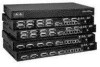
If a nonstandard value is expected that there will default to unit. Figure 2 Front Panel and LEDs 282249 CONSOLE CONSOLE CISCO 2500 Series WIRELESS CONTROLLER RESET Model 2504 1 2 3 4 PWR SYS ALM RESET 1 2 3-4 POE PWR ALM SYS Table 1 Callout WLC2504 Front Panel Component Descriptions Port and LEDs ...
If a nonstandard value is expected that there will default to unit. Figure 2 Front Panel and LEDs 282249 CONSOLE CONSOLE CISCO 2500 Series WIRELESS CONTROLLER RESET Model 2504 1 2 3 4 PWR SYS ALM RESET 1 2 3-4 POE PWR ALM SYS Table 1 Callout WLC2504 Front Panel Component Descriptions Port and LEDs ...

Getting Started Guide
Page 6
This port is designed so that 1500 VAC rms isolation (per the 802.3 specification) is configured to I2C address 0x40/41 (0100 000r/w). The POE controller is met between chassis ground and any 48V/Ethernet signal. The POE controller reset is an RJ-45 connector form-factor. Callout Port and LEDs State and Description 1 GigE port and LED The Gigabit Ethernet port is driven from system reset. LED description: • Green or Blinking Green-Link activity • Off-No link 2 GigE port and LED The Gigabit Ethernet port is met between the PSE controller and host CPU ...
This port is designed so that 1500 VAC rms isolation (per the 802.3 specification) is configured to I2C address 0x40/41 (0100 000r/w). The POE controller is met between chassis ground and any 48V/Ethernet signal. The POE controller reset is an RJ-45 connector form-factor. Callout Port and LEDs State and Description 1 GigE port and LED The Gigabit Ethernet port is driven from system reset. LED description: • Green or Blinking Green-Link activity • Off-No link 2 GigE port and LED The Gigabit Ethernet port is met between the PSE controller and host CPU ...
Getting Started Guide
Page 7
For example, a temperature error exists. Caution Do not connect a Power over Ethernet (PoE) cable to the system The system LED determines if the system is posted on the console screen. The power LED light is active and waiting for user input from the system console. • Blinking Green-Boot-loader or booting. • Green-Normal System Operation. • Amber-System failed the bootup process or an error caused the system to halt. LED description: • Blinking Amber-Boot-loader is on when all the power conversion circuits are running normally. A status or error message is ...
For example, a temperature error exists. Caution Do not connect a Power over Ethernet (PoE) cable to the system The system LED determines if the system is posted on the console screen. The power LED light is active and waiting for user input from the system console. • Blinking Green-Boot-loader or booting. • Green-Normal System Operation. • Amber-System failed the bootup process or an error caused the system to halt. LED description: • Blinking Amber-Boot-loader is on when all the power conversion circuits are running normally. A status or error message is ...

Getting Started Guide
Page 8
... the system board from the 48 VDC input. Security locking slot. 8 Figure 3 shows the back panel and identifies its components. Cable Lock slot Note The Cisco 2106 power adapter is provided via an external AC/DC adapter. Figure 3 Controller Back Panel and Components 282250 POWER 48VDC Cable Lock Slot Table 2 Controller...
... the system board from the 48 VDC input. Security locking slot. 8 Figure 3 shows the back panel and identifies its components. Cable Lock slot Note The Cisco 2106 power adapter is provided via an external AC/DC adapter. Figure 3 Controller Back Panel and Components 282250 POWER 48VDC Cable Lock Slot Table 2 Controller...

Getting Started Guide
Page 9
... modem serial cable to the shipping container and save it for damage. If any item is damaged or missing, notify your authorized Cisco sales representative. Network, operating system service network, and access point cables as required • Command-line interface (CLI) console -...) - Required Tools and Information You will need the following items: • One Cisco 2504 Wireless Controller. • One Power supply and power cord (power cord option configurable). • Cisco 2504 Wireless Controller software pre-loaded on the controller (software option configurable). • Optional...
... modem serial cable to the shipping container and save it for damage. If any item is damaged or missing, notify your authorized Cisco sales representative. Network, operating system service network, and access point cables as required • Command-line interface (CLI) console -...) - Required Tools and Information You will need the following items: • One Cisco 2504 Wireless Controller. • One Power supply and power cord (power cord option configurable). • Cisco 2504 Wireless Controller software pre-loaded on the controller (software option configurable). • Optional...

Getting Started Guide
Page 10
...• A virtual gateway IP address (a fictitious, unassigned IP address, such as 1.1.1.1, used by all Cisco wireless controller Layer 3 security and mobility managers). • A Cisco wireless controller mobility or RF group name, such as wlan1. No is more convenient, but has higher security and works well for ...port) IP address, such as 10.40.0.4. • A management interface netmask address, such as 255.255.255.0. • A management interface default router IP address, such as 10.40.0.5. • A VLAN identifier if the management interface is assigned to a VLAN, such as 40 or 0 ...
...• A virtual gateway IP address (a fictitious, unassigned IP address, such as 1.1.1.1, used by all Cisco wireless controller Layer 3 security and mobility managers). • A Cisco wireless controller mobility or RF group name, such as wlan1. No is more convenient, but has higher security and works well for ...port) IP address, such as 10.40.0.4. • A management interface netmask address, such as 255.255.255.0. • A management interface default router IP address, such as 10.40.0.5. • A VLAN identifier if the management interface is assigned to a VLAN, such as 40 or 0 ...

Getting Started Guide
Page 11
...reliable if you are configuring a RADIUS server, such as 10.40.0.3, 1812, and mysecretcode. • The country code for country code information. Leave at cisco.com. • Status of the 802.11a, 802.11b, 802.11g, or 802.11n networks, either enabled or disabled. • Status of Radio ... guidelines: • Make sure you can install the controller almost anywhere, but it is within 328 ft. (100 m) of equipment connected to the Cisco Wireless LAN Controller Configuration Guide for this installation. Enter help to see a list or refer to the 10/100/1000 Mb/s Ethernet ports. •...
...reliable if you are configuring a RADIUS server, such as 10.40.0.3, 1812, and mysecretcode. • The country code for country code information. Leave at cisco.com. • Status of the 802.11a, 802.11b, 802.11g, or 802.11n networks, either enabled or disabled. • Status of Radio ... guidelines: • Make sure you can install the controller almost anywhere, but it is within 328 ft. (100 m) of equipment connected to the Cisco Wireless LAN Controller Configuration Guide for this installation. Enter help to see a list or refer to the 10/100/1000 Mb/s Ethernet ports. •...
Getting Started Guide
Page 12
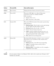
Remove the four rubber feet from the adhesive strip and attach the feet to the controller, follow these steps: Step 1 Step 2 Locate the adhesive strip with the controller. Figure 4 Installing the Rubber Feet on a desktop or shelf, install the rubber feet located in accessory kit shipped with the rubber feet in Figure 4. To install the rubber feet to the recessed areas on the bottom of the Controller 282084 12 Note We strongly recommend that you attach the rubber feet. • Mounting the Controller on a Wall (Rack-Mount Brackets) • Mounting the Controller on a ...
Remove the four rubber feet from the adhesive strip and attach the feet to the controller, follow these steps: Step 1 Step 2 Locate the adhesive strip with the controller. Figure 4 Installing the Rubber Feet on a desktop or shelf, install the rubber feet located in accessory kit shipped with the rubber feet in Figure 4. To install the rubber feet to the recessed areas on the bottom of the Controller 282084 12 Note We strongly recommend that you attach the rubber feet. • Mounting the Controller on a Wall (Rack-Mount Brackets) • Mounting the Controller on a ...

Getting Started Guide
Page 13
.... Mounting the Controller on a wall using an optional rack-mount bracket kit that is not included with 19-inch rack mounting brackets and hardware from Cisco. Statement 378 To mount the controller on a wall using the CLI setup program, see the "Running the Bootup Script and Power-On Self Test" section...
.... Mounting the Controller on a wall using an optional rack-mount bracket kit that is not included with 19-inch rack mounting brackets and hardware from Cisco. Statement 378 To mount the controller on a wall using the CLI setup program, see the "Running the Bootup Script and Power-On Self Test" section...

Getting Started Guide
Page 14
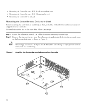
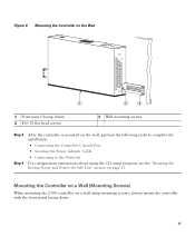
Figure 5 Installing the Rack-Mount Brackets to the Sides of the Controller 1 282083 BASE MOUNT 1 1 #10-32 flat head screws (mounting screws for each side of the controller and cables, make sure the controller is attached securely to wall studs or to a firmly attached plywood mounting backboard. 14 For the best support of the controller) Step 2 Mount the 2504 controller on the wall with the front panel facing down, as shown Figure 6.
Figure 5 Installing the Rack-Mount Brackets to the Sides of the Controller 1 282083 BASE MOUNT 1 1 #10-32 flat head screws (mounting screws for each side of the controller and cables, make sure the controller is attached securely to wall studs or to a firmly attached plywood mounting backboard. 14 For the best support of the controller) Step 2 Mount the 2504 controller on the wall with the front panel facing down, as shown Figure 6.
Getting Started Guide
Page 15
Mounting the Controller on a Wall (Mounting Screws) When mounting the 2504 controller on page 23. Figure 6 Mounting the Controller on the Wall 282085 1 2 3 1 Front panel (facing down) 2 #10-32 flat head screws 3 Wall mounting screws Step 3 Step 4 After the controller is mounted on the wall, perform the following tasks to complete the installation: • Connecting the Controller Console Port • Securing the Power Adapter Cable • Connecting to the Network For configuration instructions about using the CLI setup program, see the "Running the Bootup Script and Power-On ...
Mounting the Controller on a Wall (Mounting Screws) When mounting the 2504 controller on page 23. Figure 6 Mounting the Controller on the Wall 282085 1 2 3 1 Front panel (facing down) 2 #10-32 flat head screws 3 Wall mounting screws Step 3 Step 4 After the controller is mounted on the wall, perform the following tasks to complete the installation: • Connecting the Controller Console Port • Securing the Power Adapter Cable • Connecting to the Network For configuration instructions about using the CLI setup program, see the "Running the Bootup Script and Power-On ...

Getting Started Guide
Page 16
Insert two screws into the screw holes and tighten until the top of the Controller 5.5 3.9 282087 FRONT PANEL Step 2 Step 3 Use a 0.107-inch (2.7mm) or #32 drill bit to drill a 3/4 inch (19mm) hole for the two mounting screws. Failure to use the correct hardware or to follow these steps: Step 1 Mark the location of the mounting screws (Figure 7). (The mount holes are 1/8 inch from the wall (leaving enough room for placement of the mounting screws on the wall. Warning Read the wall-mounting carefully before beginning installation. Use the mount hole locations on the back of ...
Insert two screws into the screw holes and tighten until the top of the Controller 5.5 3.9 282087 FRONT PANEL Step 2 Step 3 Use a 0.107-inch (2.7mm) or #32 drill bit to drill a 3/4 inch (19mm) hole for the two mounting screws. Failure to use the correct hardware or to follow these steps: Step 1 Mark the location of the mounting screws (Figure 7). (The mount holes are 1/8 inch from the wall (leaving enough room for placement of the mounting screws on the wall. Warning Read the wall-mounting carefully before beginning installation. Use the mount hole locations on the back of ...

Getting Started Guide
Page 17
Step 4 Place the controller onto the mounting screws and slide it lock into place, as shown in Figure 8. Note The front panel of the controller should be facing down until it down . Figure 8 Place the Controller on the Mounting Screws 282085 2 1 2 1 Front panel (facing down) 2 Mounting screws Step 5 After the controller is mounted ion the wall, perform the following tasks to complete the installation: • Connecting the Controller Console Port • Securing the Power Adapter Cable • Connecting to the Network 17
Step 4 Place the controller onto the mounting screws and slide it lock into place, as shown in Figure 8. Note The front panel of the controller should be facing down until it down . Figure 8 Place the Controller on the Mounting Screws 282085 2 1 2 1 Front panel (facing down) 2 Mounting screws Step 5 After the controller is mounted ion the wall, perform the following tasks to complete the installation: • Connecting the Controller Console Port • Securing the Power Adapter Cable • Connecting to the Network 17

Getting Started Guide
Page 18
Statement 1006 To install the controller in the kit. 18 The following guidelines are provided to ensure your safety: • This unit should be mounted at the bottom of the rack if it is the only unit in the rack. • When mounting this unit in the rack. Step 6 For configuration instructions about using the CLI setup program, see the "Running the Bootup Script and Power-On Self Test" section on page 23. Step 1 Attach the 19-inch brackets to ensure that the system remains stable. Warning To prevent bodily injury when mounting or servicing this unit in a partially filled ...
Statement 1006 To install the controller in the kit. 18 The following guidelines are provided to ensure your safety: • This unit should be mounted at the bottom of the rack if it is the only unit in the rack. • When mounting this unit in the rack. Step 6 For configuration instructions about using the CLI setup program, see the "Running the Bootup Script and Power-On Self Test" section on page 23. Step 1 Attach the 19-inch brackets to ensure that the system remains stable. Warning To prevent bodily injury when mounting or servicing this unit in a partially filled ...
Getting Started Guide
Page 19
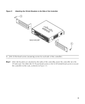
282082 Figure 9 Attaching the 19-Inch Brackets to the Side of the Controller. 1 RACK MOUNT 1 1 #10-32 flat head screws (mounting screws for each side of the controller, insert the controller into the 19-inch rack. Use either the 10-32 pan-head screws or the 12-24 slotted head screws to the sides of the controller) Step 2 After the brackets are attached to secure the controller in the rack, as shown in Figure 10. 19
282082 Figure 9 Attaching the 19-Inch Brackets to the Side of the Controller. 1 RACK MOUNT 1 1 #10-32 flat head screws (mounting screws for each side of the controller, insert the controller into the 19-inch rack. Use either the 10-32 pan-head screws or the 12-24 slotted head screws to the sides of the controller) Step 2 After the brackets are attached to secure the controller in the rack, as shown in Figure 10. 19

Getting Started Guide
Page 20
Figure 10 Mounting the Controller in a 19-Inch Rack 1 282086 1 #10-32 pan-head screws or #12-24 slotted head screws Step 3 Step 4 After the controller is mounted in the rack, perform the following tasks to complete the installation: • Connecting the Controller Console Port • Securing the Power Adapter Cable • Connecting to the Network For configuration instructions about using the CLI setup program, see the "Running the Bootup Script and Power-On Self Test" section on page 23. 20
Figure 10 Mounting the Controller in a 19-Inch Rack 1 282086 1 #10-32 pan-head screws or #12-24 slotted head screws Step 3 Step 4 After the controller is mounted in the rack, perform the following tasks to complete the installation: • Connecting the Controller Console Port • Securing the Power Adapter Cable • Connecting to the Network For configuration instructions about using the CLI setup program, see the "Running the Bootup Script and Power-On Self Test" section on page 23. 20