

Getting Started Guide
Page 1
GETTING STARTED GUIDE Cisco 2500 Series Wireless Controller May 2011 Revised June 2, 2011 1 About This Guide 2 Unpacking and Preparing the Controller for Operation 3 Installing the Controller 4 Running the Bootup Script and Power-On Self Test 5 Logging into the Controller 6 Connecting to the Network 7 What's New in Cisco Product Documentation 8 Translated Safety Warnings
GETTING STARTED GUIDE Cisco 2500 Series Wireless Controller May 2011 Revised June 2, 2011 1 About This Guide 2 Unpacking and Preparing the Controller for Operation 3 Installing the Controller 4 Running the Bootup Script and Power-On Self Test 5 Logging into the Controller 6 Connecting to the Network 7 What's New in Cisco Product Documentation 8 Translated Safety Warnings

Getting Started Guide
Page 2
...following measures: • Reorient or relocate the receiving antenna. • Increase the separation between the equipment and receiver. • Connect the equipment to an outlet on any equipment, be determined by one or more of each warning statement. Warning This warning symbol ...Compliance Statement This equipment has been tested and found to comply with the instructions, may harm you install and minimally configure your Cisco 2504 Wireless Controller (2504 controller), which can radiate radio frequency energy and, if not installed and used in a residential installation....
...following measures: • Reorient or relocate the receiving antenna. • Increase the separation between the equipment and receiver. • Connect the equipment to an outlet on any equipment, be determined by one or more of each warning statement. Warning This warning symbol ...Compliance Statement This equipment has been tested and found to comply with the instructions, may harm you install and minimally configure your Cisco 2504 Wireless Controller (2504 controller), which can radiate radio frequency energy and, if not installed and used in a residential installation....

Getting Started Guide
Page 4
.... Figure 1 Typical Controller Topology and Network Connections Console emulator for initial boot-up Null modem serial cable (DB-9 -> RJ-45) to console connection Cisco WCS software, web user interface 10/100/1000BASE-T MDI cable Network Distribution system connection LAN link for management software connections WAN or LAN connection to Cisco 2500 Series Wireless Controllers are not currently...
.... Figure 1 Typical Controller Topology and Network Connections Console emulator for initial boot-up Null modem serial cable (DB-9 -> RJ-45) to console connection Cisco WCS software, web user interface 10/100/1000BASE-T MDI cable Network Distribution system connection LAN link for management software connections WAN or LAN connection to Cisco 2500 Series Wireless Controllers are not currently...

Getting Started Guide
Page 6
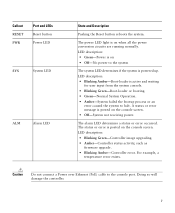
.... The POE controller is an RJ-45 connector form-factor. If software needs to reset the POE controller, it can be used for infra-switch connection using multiple an AP-Manager or data interface. 6 LED description: • Green or Blinking Green-Link activity • Off-No link 2 GigE port and LED...
.... The POE controller is an RJ-45 connector form-factor. If software needs to reset the POE controller, it can be used for infra-switch connection using multiple an AP-Manager or data interface. 6 LED description: • Green or Blinking Green-Link activity • Off-No link 2 GigE port and LED...
Getting Started Guide
Page 7
... occurred. A status or error message is posted on the console screen. • Off-System not receiving power. For example, a temperature error exists. Caution Do not connect a Power over Ethernet (PoE) cable to halt. LED description: • Green-Power is powered up. The power LED light is on • Off-No power...
... occurred. A status or error message is posted on the console screen. • Off-System not receiving power. For example, a temperature error exists. Caution Do not connect a Power over Ethernet (PoE) cable to halt. LED description: • Green-Power is powered up. The power LED light is on • Off-No power...

Getting Started Guide
Page 9
... - Required Tools and Information You will be included, if selected. If any item is damaged or missing, notify your authorized Cisco sales representative. Controller with factory-supplied power cord and mounting hardware - Null modem serial cable to the shipping container and save ...and Preparing the Controller for Operation Follow these steps to unpack the 2504 controller and prepare it . Ensure that all packing materials to connect CLI console and controller 9 Network, operating system service network, and access point cables as required • Command-line interface (CLI)...
... - Required Tools and Information You will be included, if selected. If any item is damaged or missing, notify your authorized Cisco sales representative. Controller with factory-supplied power cord and mounting hardware - Null modem serial cable to the shipping container and save ...and Preparing the Controller for Operation Follow these steps to unpack the 2504 controller and prepare it . Ensure that all packing materials to connect CLI console and controller 9 Network, operating system service network, and access point cables as required • Command-line interface (CLI)...

Getting Started Guide
Page 11
...240 VAC grounded electrical outlet. 3 Installing the Controller This section includes the following installation procedures: • Mounting the Controller, page 11 • Connecting the Controller Console Port, page 21 • Securing the Power Adapter Cable, page 21 • Installing a Security Lock, page 23 Mounting ...configuring a RADIUS server, such as 10.40.0.3, 1812, and mysecretcode. • The country code for country code information. Leave at cisco.com. • Status of the 802.11a, 802.11b, 802.11g, or 802.11n networks, either enabled or disabled. • Status of...
...240 VAC grounded electrical outlet. 3 Installing the Controller This section includes the following installation procedures: • Mounting the Controller, page 11 • Connecting the Controller Console Port, page 21 • Securing the Power Adapter Cable, page 21 • Installing a Security Lock, page 23 Mounting ...configuring a RADIUS server, such as 10.40.0.3, 1812, and mysecretcode. • The country code for country code information. Leave at cisco.com. • Status of the 802.11a, 802.11b, 802.11g, or 802.11n networks, either enabled or disabled. • Status of...

Getting Started Guide
Page 13
...mounted on a shelf or desk, perform the following tasks to complete the installation: • Connecting the Controller Console Port • Securing the Power Adapter Cable • Connecting to prevent airflow restriction and overheating. Mounting the Controller on a wall using an optional rack-...mount bracket kit that is not included with 19-inch rack mounting brackets and hardware from Cisco. You can be mounted on a...
...mounted on a shelf or desk, perform the following tasks to complete the installation: • Connecting the Controller Console Port • Securing the Power Adapter Cable • Connecting to prevent airflow restriction and overheating. Mounting the Controller on a wall using an optional rack-...mount bracket kit that is not included with 19-inch rack mounting brackets and hardware from Cisco. You can be mounted on a...
Getting Started Guide
Page 15
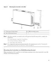
... Step 3 Step 4 After the controller is mounted on the wall, perform the following tasks to complete the installation: • Connecting the Controller Console Port • Securing the Power Adapter Cable • Connecting to the Network For configuration instructions about using the CLI setup program, see the "Running the Bootup Script and Power...
... Step 3 Step 4 After the controller is mounted on the wall, perform the following tasks to complete the installation: • Connecting the Controller Console Port • Securing the Power Adapter Cable • Connecting to the Network For configuration instructions about using the CLI setup program, see the "Running the Bootup Script and Power...

Getting Started Guide
Page 17
Figure 8 Place the Controller on the Mounting Screws 282085 2 1 2 1 Front panel (facing down . Note The front panel of the controller should be facing down ) 2 Mounting screws Step 5 After the controller is mounted ion the wall, perform the following tasks to complete the installation: • Connecting the Controller Console Port • Securing the Power Adapter Cable • Connecting to the Network 17 Step 4 Place the controller onto the mounting screws and slide it down until it lock into place, as shown in Figure 8.
Figure 8 Place the Controller on the Mounting Screws 282085 2 1 2 1 Front panel (facing down . Note The front panel of the controller should be facing down ) 2 Mounting screws Step 5 After the controller is mounted ion the wall, perform the following tasks to complete the installation: • Connecting the Controller Console Port • Securing the Power Adapter Cable • Connecting to the Network 17 Step 4 Place the controller onto the mounting screws and slide it down until it lock into place, as shown in Figure 8.

Getting Started Guide
Page 20
Figure 10 Mounting the Controller in a 19-Inch Rack 1 282086 1 #10-32 pan-head screws or #12-24 slotted head screws Step 3 Step 4 After the controller is mounted in the rack, perform the following tasks to complete the installation: • Connecting the Controller Console Port • Securing the Power Adapter Cable • Connecting to the Network For configuration instructions about using the CLI setup program, see the "Running the Bootup Script and Power-On Self Test" section on page 23. 20
Figure 10 Mounting the Controller in a 19-Inch Rack 1 282086 1 #10-32 pan-head screws or #12-24 slotted head screws Step 3 Step 4 After the controller is mounted in the rack, perform the following tasks to complete the installation: • Connecting the Controller Console Port • Securing the Power Adapter Cable • Connecting to the Network For configuration instructions about using the CLI setup program, see the "Running the Bootup Script and Power-On Self Test" section on page 23. 20
Getting Started Guide
Page 21
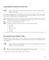
.... To secure the power adapter cable and plug, follow these steps: 21 To connect the PC to a PC that uses a VT-100 terminal emulator (such as HyperTerminal, ProComm, Minicom, or Tip). Note The Cisco 2106 power adapter is pulled or if the power adapter falls. Start the PC... terminal emulation program. Connecting the Controller Console Port Caution Do not connect a Power over Ethernet (PoE) cable to the 2504 controller, use the ...
.... To secure the power adapter cable and plug, follow these steps: 21 To connect the PC to a PC that uses a VT-100 terminal emulator (such as HyperTerminal, ProComm, Minicom, or Tip). Note The Cisco 2106 power adapter is pulled or if the power adapter falls. Start the PC... terminal emulation program. Connecting the Controller Console Port Caution Do not connect a Power over Ethernet (PoE) cable to the 2504 controller, use the ...

Getting Started Guide
Page 23
... PC to the controller are correct. 23 If the Power LED does not light, make sure that the power connections to the CLI console on the back of the controller. Refer to Figure 3 for the location of the controller code, press Esc when the boot ... adapter cable Power plugged into a grounded 100 to secure the controller. You can install an optional customer-supplied cable lock, such as described in the "Connecting the Controller Console Port" section on the back panel. To run a previous release of the security lock. 4 Running the Bootup Script and Power-On Self...
... PC to the controller are correct. 23 If the Power LED does not light, make sure that the power connections to the CLI console on the back of the controller. Refer to Figure 3 for the location of the controller code, press Esc when the boot ... adapter cable Power plugged into a grounded 100 to secure the controller. You can install an optional customer-supplied cable lock, such as described in the "Connecting the Controller Console Port" section on the back panel. To run a previous release of the security lock. 4 Running the Bootup Script and Power-On Self...

Getting Started Guide
Page 30
... characters. You can enter up to 4] Note There is the default interface for each . Management Interface IP Address Management Interface Netmask Management Interface Default Router Management Interface VLAN Identifier Management Interface Port Num [1 to 24 ASCII characters for an untagged VLAN). You can enter from 3 to enterprise services such... interface. The default administrative username is the name you want to assign to the controller. Enter the IP address of the controller and connectivity to 24 ASCII characters for in-band management of the management interface.
... characters. You can enter up to 4] Note There is the default interface for each . Management Interface IP Address Management Interface Netmask Management Interface Default Router Management Interface VLAN Identifier Management Interface Port Num [1 to 24 ASCII characters for an untagged VLAN). You can enter from 3 to enterprise services such... interface. The default administrative username is the name you want to assign to the controller. Enter the IP address of the controller and connectivity to 24 ASCII characters for in-band management of the management interface.

Getting Started Guide
Page 34
...MDI cable 282298 Note The CLI automatically logs out without saving any alphanumeric string up to CISCO2504, enter config prompt "CISCO2504" and press Enter. The connection uses 10/100/1000BASE-T Ethernet (RJ-45 physical port, UTP, Category-5 or higher cable). Step 2 The CLI displays the root level system prompt:... logout from 0 (never log out) to 160 minutes using double quotation marks. For example, to the controller. Figure 13 External Network Equipment Connection to the Controller 10/100/1000BASE-T MDI cable Cisco Access Points CLI console Connection to the controller.
...MDI cable 282298 Note The CLI automatically logs out without saving any alphanumeric string up to CISCO2504, enter config prompt "CISCO2504" and press Enter. The connection uses 10/100/1000BASE-T Ethernet (RJ-45 physical port, UTP, Category-5 or higher cable). Step 2 The CLI displays the root level system prompt:... logout from 0 (never log out) to 160 minutes using double quotation marks. For example, to the controller. Figure 13 External Network Equipment Connection to the Controller 10/100/1000BASE-T MDI cable Cisco Access Points CLI console Connection to the controller.

Getting Started Guide
Page 35
... MAC address in Figure 14. You have configured the controller, use Category-5, Category-5e, Category-6, or Category-7 Ethernet cables to connect up to 50 Cisco lightweight access points to the controller Ethernet ports or to meet the specific needs of access points to... Cisco 2500 Series Wireless Controllers are connecting to connect access that are scanning for basic operation. Refer to the Cisco Wireless LAN Controller Configuration Guide for information on configuring the controller to the network (...
... MAC address in Figure 14. You have configured the controller, use Category-5, Category-5e, Category-6, or Category-7 Ethernet cables to connect up to 50 Cisco lightweight access points to the controller Ethernet ports or to meet the specific needs of access points to... Cisco 2500 Series Wireless Controllers are connecting to connect access that are scanning for basic operation. Refer to the Cisco Wireless LAN Controller Configuration Guide for information on configuring the controller to the network (...

Getting Started Guide
Page 36
...Reset button, follow these steps: Step 1 Connect a PC to the controller console point. 36 The guide is not working properly, check the LEDs on the front panel of the unit. Figure 14 Access Points Connected to a Controller Network Cisco 2504 Wireless Controller 10/100/1000BASE-T MDI ...cable Network 10/100/1000BASE-T MDI cables 282081 Cisco Access Points Checking the Controller LEDs If your controller. The installation is complete....
...Reset button, follow these steps: Step 1 Connect a PC to the controller console point. 36 The guide is not working properly, check the LEDs on the front panel of the unit. Figure 14 Access Points Connected to a Controller Network Cisco 2504 Wireless Controller 10/100/1000BASE-T MDI ...cable Network 10/100/1000BASE-T MDI cables 282081 Cisco Access Points Checking the Controller LEDs If your controller. The installation is complete....
Getting Started Guide
Page 55
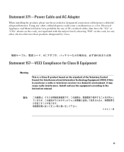
... subject law by showing "PSE" on the standard of the Voluntary Control Council for any other electrical devices than products designated by Cisco. Install and use the provided or designated connection cables/power cables/AC adaptors/batteries. Statement 371-Power Cable and AC Adapter When installing the product, please use the equipment...
... subject law by showing "PSE" on the standard of the Voluntary Control Council for any other electrical devices than products designated by Cisco. Install and use the provided or designated connection cables/power cables/AC adaptors/batteries. Statement 371-Power Cable and AC Adapter When installing the product, please use the equipment...


