
Hardware Guide
Page 64
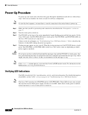
... has two SYS PWR and two AUX PWR LEDs. Powering Up Cisco 3800 Series Routers 34 OL-5971-01 Turn the router power switch on the front of the router immediately begins blinking green and the fans operate. For information on the ROM monitor, see the "LEDs" section on page 41 of... the "Prerequisites" section on your router has booted in Table 4 provide power, activity, and status information. The SYS PWR1 and SYS PWR2 LEDs on the Cisco 3845 router do not come on . Any keys pressed during the power-up and connected as router power is turned on yet. If these steps. The...
... has two SYS PWR and two AUX PWR LEDs. Powering Up Cisco 3800 Series Routers 34 OL-5971-01 Turn the router power switch on the front of the router immediately begins blinking green and the fans operate. For information on the ROM monitor, see the "LEDs" section on page 41 of... the "Prerequisites" section on your router has booted in Table 4 provide power, activity, and status information. The SYS PWR1 and SYS PWR2 LEDs on the Cisco 3845 router do not come on . Any keys pressed during the power-up and connected as router power is turned on yet. If these steps. The...

Hardware Guide
Page 68
... to locate or eliminate faults in the "LEDs" section on , the SYS LED steady green, and the SYS PWR LED (Cisco 3825) or SYS PWR1 or SYS PWR2 LED (Cisco 3845) steady green, do the fans operate? - If the LED is amber, the router is receiving power but is functioning. - Troubleshooting... Cooling Systems Both the system power LED and the fans can help identify a failure. • Cables-External cables that connect the router to the network. Check the following items. Note The Cisco 3845 router has two system power LEDs, one for the Cisco 3845 router (depending on , what it should be doing...
... to locate or eliminate faults in the "LEDs" section on , the SYS LED steady green, and the SYS PWR LED (Cisco 3825) or SYS PWR1 or SYS PWR2 LED (Cisco 3845) steady green, do the fans operate? - If the LED is amber, the router is receiving power but is functioning. - Troubleshooting... Cooling Systems Both the system power LED and the fans can help identify a failure. • Cables-External cables that connect the router to the network. Check the following items. Note The Cisco 3845 router has two system power LEDs, one for the Cisco 3845 router (depending on , what it should be doing...
Hardware Guide
Page 69
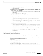
... router shut down after being on . - Solving Problems • With the power switch on and the SYS PWR LED (Cisco 3825) or SYS PWR1 or SYS PWR2 LED (Cisco 3845) off, do the fans operate? - If yes, the power system is active). Environmental Reporting Features If the router is operating at an abnormally high...
... router shut down after being on . - Solving Problems • With the power switch on and the SYS PWR LED (Cisco 3825) or SYS PWR1 or SYS PWR2 LED (Cisco 3845) off, do the fans operate? - If yes, the power system is active). Environmental Reporting Features If the router is operating at an abnormally high...
Hardware Guide
Page 75
SYS PS1 is Normal, Current voltage = 1191 mV OL-5972-01 Troubleshooting Cisco 3800 Series Routers 45 Fan 1 Normal Fan 2 Normal Fan 3 Normal Fan Speed is Normal Alert settings: Intake temperature warning: Enabled, Threshold: 50 Core temperature warning: Enabled, Threshold: 70 (CPU: 95) Board Temperature:... Steady green Present and enabled Amber Present and off or malfunctioning The show environment Command The show environment Command Table 5 Cisco 3800 Series LED Indicators (continued) LED 3825 3845 GE0: Speed Rear Rear GE1: Link Rear Rear GE1: Speed Rear Rear PS1 -
SYS PS1 is Normal, Current voltage = 1191 mV OL-5972-01 Troubleshooting Cisco 3800 Series Routers 45 Fan 1 Normal Fan 2 Normal Fan 3 Normal Fan Speed is Normal Alert settings: Intake temperature warning: Enabled, Threshold: 50 Core temperature warning: Enabled, Threshold: 70 (CPU: 95) Board Temperature:... Steady green Present and enabled Amber Present and off or malfunctioning The show environment Command The show environment Command Table 5 Cisco 3800 Series LED Indicators (continued) LED 3825 3845 GE0: Speed Rear Rear GE1: Link Rear Rear GE1: Speed Rear Rear PS1 -

Hardware Guide
Page 76
... This is an example of the output of the show environment command for a Cisco 3845 router that has one AC power supply with IP phone power output installed: Router# show environment SYS PS1 is present Fan status: Normal Input Voltage status: Normal DC Output Voltage status: Normal Type:... AC Thermal status: Normal SYS PS2 is absent AUX (-48V) PS1 is present AUX (-48V) PS2 is absent Fan 1 Normal Fan 2 Normal Fan 3 Normal Fan Speed is Normal Alert settings: Intake temperature warning: Enabled, Threshold: 50 Core temperature warning: Enabled, Threshold: 70 (CPU: 90) Board...
... This is an example of the output of the show environment command for a Cisco 3845 router that has one AC power supply with IP phone power output installed: Router# show environment SYS PS1 is present Fan status: Normal Input Voltage status: Normal DC Output Voltage status: Normal Type:... AC Thermal status: Normal SYS PS2 is absent AUX (-48V) PS1 is present AUX (-48V) PS2 is absent Fan 1 Normal Fan 2 Normal Fan 3 Normal Fan Speed is Normal Alert settings: Intake temperature warning: Enabled, Threshold: 50 Core temperature warning: Enabled, Threshold: 70 (CPU: 90) Board...

Hardware Guide
Page 77
... AUX (-48V) PS 1|2 fail condition. Error Messages Error Message Fan 1|2|3 had a rotation error reported. Explanation The specified fan is outside its operating limits. See "Installing and Upgrading Internal Components in Cisco 3800 Series Routers." If this error is kept at the desired speed... "Obtaining Technical Assistance" section on page 12 of the internal voltage outputs is not rotating at high. Cisco 3845 Router Error Messages The Cisco 3845 router supports two internal power supplies and returns the following error messages for information about customer service. The...
... AUX (-48V) PS 1|2 fail condition. Error Messages Error Message Fan 1|2|3 had a rotation error reported. Explanation The specified fan is outside its operating limits. See "Installing and Upgrading Internal Components in Cisco 3800 Series Routers." If this error is kept at the desired speed... "Obtaining Technical Assistance" section on page 12 of the internal voltage outputs is not rotating at high. Cisco 3845 Router Error Messages The Cisco 3845 router supports two internal power supplies and returns the following error messages for information about customer service. The...

Hardware Guide
Page 78
...turn it . The power supply fan may need to set one failure with power system 1|2 or this setting if the router consistently hangs or crashes after a ROM monitor upgrade. • WDOG DIS-Disables the watchdog timer If you may have occurred in a Cisco 3845 router, but only one is...thermal monitor automatically shuts down the router. You may need to fail. Troubleshooting Cisco 3800 Series Routers 48 OL-5972-01 See "Installing and Upgrading Internal Components in Cisco 3800 Series Routers." Explanation The fan on . Recommended Action If the power supply is powered on the indicated ...
...turn it . The power supply fan may need to set one failure with power system 1|2 or this setting if the router consistently hangs or crashes after a ROM monitor upgrade. • WDOG DIS-Disables the watchdog timer If you may have occurred in a Cisco 3845 router, but only one is...thermal monitor automatically shuts down the router. You may need to fail. Troubleshooting Cisco 3800 Series Routers 48 OL-5972-01 See "Installing and Upgrading Internal Components in Cisco 3800 Series Routers." Explanation The fan on . Recommended Action If the power supply is powered on the indicated ...

Hardware Guide
Page 107
...the front of the router. Follow the "Removing the Cover from a Cisco 3825 Router" procedure on page 82. • The Cisco 3845 router fan tray and power supplies are reached from a Cisco 3845 Router" procedure on page 80. All rights reserved. This document contains ... • Advanced integration modules (AIMs) • Packet voice data modules (PVDMs) • Power supplies • Motherboard (Cisco 3845 router only) • Fan tray (Cisco 3845 router only) For information about router SDRAM, AIM, PVDM, and power supply capacity, see the following sections: • Safety...
...the front of the router. Follow the "Removing the Cover from a Cisco 3825 Router" procedure on page 82. • The Cisco 3845 router fan tray and power supplies are reached from a Cisco 3845 Router" procedure on page 80. All rights reserved. This document contains ... • Advanced integration modules (AIMs) • Packet voice data modules (PVDMs) • Power supplies • Motherboard (Cisco 3845 router only) • Fan tray (Cisco 3845 router only) For information about router SDRAM, AIM, PVDM, and power supply capacity, see the following sections: • Safety...

Hardware Guide
Page 108
...8226; Safety with Electricity, page 79 • Removing the Cover from a Cisco 3825 Router, page 80 • Removing the Power Supply Assembly from a Cisco 3825 Router, page 81 • Removing the Plug-In Motherboard from a Cisco 3845 Router, page 82 • Component Locations on the Motherboard, page 83 ... Router, page 105 • Installing or Replacing the Plug-In Motherboard in a Cisco 3845 Router, page 105 • Removing and Installing the Fan Tray and Power Supplies in a Cisco 3845 Router, page 106 Before you perform any metal tool, or you could be installed and maintained by ...
...8226; Safety with Electricity, page 79 • Removing the Cover from a Cisco 3825 Router, page 80 • Removing the Power Supply Assembly from a Cisco 3825 Router, page 81 • Removing the Plug-In Motherboard from a Cisco 3845 Router, page 82 • Component Locations on the Motherboard, page 83 ... Router, page 105 • Installing or Replacing the Plug-In Motherboard in a Cisco 3845 Router, page 105 • Removing and Installing the Fan Tray and Power Supplies in a Cisco 3845 Router, page 106 Before you perform any metal tool, or you could be installed and maintained by ...

Hardware Guide
Page 115
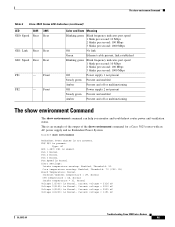
.... OL-5975-04 Installing and Upgrading Internal Components in either DIMM connector. The two DIMM slots can be installed in Cisco 3800 Series Routers 85 Figure 52 Component Locations on a Cisco 3845 Motherboard 4 3 2 1 10 7 8 5 9 6 SDRAM DIMM Removal and Installation 117937 1 PVDM3 2 PVDM2 ...3 PVDM1 4 PVDM0 5 AIM0 6 AIM1 7 MEM0 8 MEM1 9 Jumper headers 10 Power connector for fan tray assembly SDRAM DIMM Removal and Installation Cisco 3800 series routers...
.... OL-5975-04 Installing and Upgrading Internal Components in either DIMM connector. The two DIMM slots can be installed in Cisco 3800 Series Routers 85 Figure 52 Component Locations on a Cisco 3845 Motherboard 4 3 2 1 10 7 8 5 9 6 SDRAM DIMM Removal and Installation 117937 1 PVDM3 2 PVDM2 ...3 PVDM1 4 PVDM0 5 AIM0 6 AIM1 7 MEM0 8 MEM1 9 Jumper headers 10 Power connector for fan tray assembly SDRAM DIMM Removal and Installation Cisco 3800 series routers...

Hardware Guide
Page 136
... assembly. See Figure 74. Use a number 2 Phillips screwdriver to loosen these screws and remove the fan tray assembly. Removing and Installing the Fan Tray and Power Supplies in a Cisco 3845 Router Step 3 Use a number 2 Phillips screwdriver to tighten the two captive retention screws, one . ... combination of two power supplies is operating on the Front Panel of the router. Removing and Installing the Fan Tray and Power Supplies in a Cisco 3845 Router The Cisco 3845 router accommodates two hot-swappable power supplies in bays at both ends. A single power supply meets router ...
... assembly. See Figure 74. Use a number 2 Phillips screwdriver to loosen these screws and remove the fan tray assembly. Removing and Installing the Fan Tray and Power Supplies in a Cisco 3845 Router Step 3 Use a number 2 Phillips screwdriver to tighten the two captive retention screws, one . ... combination of two power supplies is operating on the Front Panel of the router. Removing and Installing the Fan Tray and Power Supplies in a Cisco 3845 Router The Cisco 3845 router accommodates two hot-swappable power supplies in bays at both ends. A single power supply meets router ...

Hardware Guide
Page 137
... of the power supply outward. See Figure 75. Fold the handle up, and pull the power supply out by the handle. Removing and Installing the Fan Tray and Power Supplies in a Cisco 3845 Router Step 2 To remove a power supply, use a flat-blade screwdriver to pry off the plastic panel from the power supply.
... of the power supply outward. See Figure 75. Fold the handle up, and pull the power supply out by the handle. Removing and Installing the Fan Tray and Power Supplies in a Cisco 3845 Router Step 2 To remove a power supply, use a flat-blade screwdriver to pry off the plastic panel from the power supply.

Hardware Guide
Page 138
Removing and Installing the Fan Tray and Power Supplies in a Cisco 3845 Router 108 Installing and Upgrading Internal Components in Cisco 3800 Series Routers OL-5975-04
Removing and Installing the Fan Tray and Power Supplies in a Cisco 3845 Router 108 Installing and Upgrading Internal Components in Cisco 3800 Series Routers OL-5975-04
