
Hardware Installation Guide
Page 6
... PC 2-17 Connecting the Power Supply 2-18 Mounting Your Router 2-18 Mounting on a Table 2-18 Mounting on a Wall 2-19 Verifying Installation 2-20 Where to Go from Here 2-22 Troubleshooting 3-1 Problems During First Startup 3-2 Problems After First Startup 3-3 Problems After Router Is Running 3-5 When Contacting Your Cisco Reseller 3-7 ISDN and IDSL Concepts A-1 Specifications and Cables B-1 System Specifications B-1 Port Connector Pinouts B-2 Cabling Specifications B-6 Ethernet Cable Specifications B-7 Maximum Cable Distances B-7 Cisco 800 Series Routers Hardware Installation Guide vi 78-5373...
... PC 2-17 Connecting the Power Supply 2-18 Mounting Your Router 2-18 Mounting on a Table 2-18 Mounting on a Wall 2-19 Verifying Installation 2-20 Where to Go from Here 2-22 Troubleshooting 3-1 Problems During First Startup 3-2 Problems After First Startup 3-3 Problems After Router Is Running 3-5 When Contacting Your Cisco Reseller 3-7 ISDN and IDSL Concepts A-1 Specifications and Cables B-1 System Specifications B-1 Port Connector Pinouts B-2 Cabling Specifications B-6 Ethernet Cable Specifications B-7 Maximum Cable Distances B-7 Cisco 800 Series Routers Hardware Installation Guide vi 78-5373...

Hardware Installation Guide
Page 7
... router. • ISDN and IDSL Concepts-Describes how ISDN is to connect the router to access related documentation. • Overview-Contains router features and a description of experience in this information. Notes contain helpful suggestions or references to identify and solve problems with all technicians is implemented on the router. • Specifications and Cables-Provides router, port, and cable specifications. • Glossary-Defines technical terms frequently used in installing routers...
... router. • ISDN and IDSL Concepts-Describes how ISDN is to connect the router to access related documentation. • Overview-Contains router features and a description of experience in this information. Notes contain helpful suggestions or references to identify and solve problems with all technicians is implemented on the router. • Specifications and Cables-Provides router, port, and cable specifications. • Glossary-Defines technical terms frequently used in installing routers...
Hardware Installation Guide
Page 16
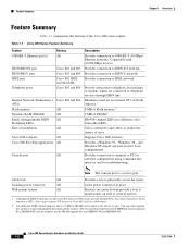
... series routers. Provides connection to Cisco 802 and Cisco 804 routers. 2. Note The console port is MEM800-8F and the numbers for the 8-MB Flash memory upgrade kit is a service port. Wall-mount feature All Brackets on router bottom provide a way to 10BASE-T (10 Mbps) Ethernet networks. Table 1-1 Cisco 800 Series Feature Summary Feature 10BASE-T Ethernet port(s) ISDN BRI S/T port ISDN BRI U port IDSL port Telephone ports Internal Network Termination 1 (NT1) Flash memory Dynamic RAM (DRAM) Easily distinguishable ISDN B-channel LEDs Ease of installation Cisco IOS software Cisco...
... series routers. Provides connection to Cisco 802 and Cisco 804 routers. 2. Note The console port is MEM800-8F and the numbers for the 8-MB Flash memory upgrade kit is a service port. Wall-mount feature All Brackets on router bottom provide a way to 10BASE-T (10 Mbps) Ethernet networks. Table 1-1 Cisco 800 Series Feature Summary Feature 10BASE-T Ethernet port(s) ISDN BRI S/T port ISDN BRI U port IDSL port Telephone ports Internal Network Termination 1 (NT1) Flash memory Dynamic RAM (DRAM) Easily distinguishable ISDN B-channel LEDs Ease of installation Cisco IOS software Cisco...
Hardware Installation Guide
Page 18
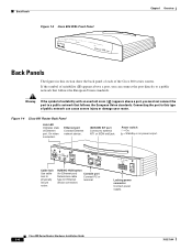
... router. Connecting the port to this section show the back panel of each of Ethernet port. Figure 1-4 Cisco 801 Router Back Panel Link LED Indicates state of the Cisco 800 series routers. Cisco 800 Series Routers Hardware Installation Guide 1-4 78-5373-04 device connection. Warning If the symbol of public network can connect the port directly to a public network that follows the European Union standards. On when connected. HUB/NO HUB button (for Ethernet port) Console port Determines cable Connect PC or type for Ethernet terminal. Power switch...
... router. Connecting the port to this section show the back panel of each of Ethernet port. Figure 1-4 Cisco 801 Router Back Panel Link LED Indicates state of the Cisco 800 series routers. Cisco 800 Series Routers Hardware Installation Guide 1-4 78-5373-04 device connection. Warning If the symbol of public network can connect the port directly to a public network that follows the European Union standards. On when connected. HUB/NO HUB button (for Ethernet port) Console port Determines cable Connect PC or type for Ethernet terminal. Power switch...
Hardware Installation Guide
Page 19
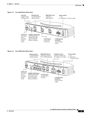
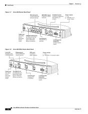
...Console port Connect PC or terminal. ISDN BRI S/T port Connect to physically secure router. Ethernet port Connect Ethernet network device. HUB/NO HUB button (for Ethernet port) Determines cable type for Ethernet device connection. Power switch l = On. = Standby or no power output. 11668 Cable lock Use cable lock to physically secure router. Chapter 1 Overview Back Panels Figure 1-5 Cisco 802 Router Back Panel Link LED Indicates state of Ethernet port. PHONE 1 2 Locking power connector Connect power supply. 78-5373-04 Cisco 800 Series Routers Hardware Installation Guide...
...Console port Connect PC or terminal. ISDN BRI S/T port Connect to physically secure router. Ethernet port Connect Ethernet network device. HUB/NO HUB button (for Ethernet port) Determines cable type for Ethernet device connection. Power switch l = On. = Standby or no power output. 11668 Cable lock Use cable lock to physically secure router. Chapter 1 Overview Back Panels Figure 1-5 Cisco 802 Router Back Panel Link LED Indicates state of Ethernet port. PHONE 1 2 Locking power connector Connect power supply. 78-5373-04 Cisco 800 Series Routers Hardware Installation Guide...
Hardware Installation Guide
Page 20
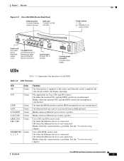
...Cisco 804 CONSOLE ISDN U Console port Connect PC or terminal. LINK TO TO HUB PC ETHERNET 10 BASE T CONSOLE Cisco 802 IDSL IDSL Cable lock Use cable lock to ISDN wall jack. Locking power connector Connect power supply. 30771 Cisco 800 Series Routers Hardware Installation Guide 1-6 78-5373-04 ISDN BRI U port Connect to physically secure router. PHONE 1 2 Locking power connector Connect power supply. IDSL port Connect to telephone, fax machine, or modem. Telephone ports Connect to IDSL wall jack. Ethernet port Connect Ethernet network device. Console port...
...Cisco 804 CONSOLE ISDN U Console port Connect PC or terminal. LINK TO TO HUB PC ETHERNET 10 BASE T CONSOLE Cisco 802 IDSL IDSL Cable lock Use cable lock to ISDN wall jack. Locking power connector Connect power supply. 30771 Cisco 800 Series Routers Hardware Installation Guide 1-6 78-5373-04 ISDN BRI U port Connect to physically secure router. PHONE 1 2 Locking power connector Connect power supply. IDSL port Connect to telephone, fax machine, or modem. Telephone ports Connect to IDSL wall jack. Ethernet port Connect Ethernet network device. Console port...
Hardware Installation Guide
Page 21
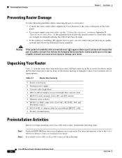
... Ethernet device connection. Blinks when the connection has a problem. Chapter 1 Overview LEDs Figure 1-9 Cisco 804 IDSL Router Back Panel Ethernet ports Connect Ethernet network devices. On when the ISDN interface and the ISDN terminal device are sent to the router and when the router completes the self-test procedure and begins operating. Cisco 804 IDSL CONSOLE IDSL Console port Connect PC or terminal. Cisco 803 and 804 routers only. Table 1-3 LED Functions LED Color OK Green NT1 Green LINE LAN LAN RXD LAN TXD LKØ, LK1, LK2, LK3 Green Green Green Green Green...
... Ethernet device connection. Blinks when the connection has a problem. Chapter 1 Overview LEDs Figure 1-9 Cisco 804 IDSL Router Back Panel Ethernet ports Connect Ethernet network devices. On when the ISDN interface and the ISDN terminal device are sent to the router and when the router completes the self-test procedure and begins operating. Cisco 804 IDSL CONSOLE IDSL Console port Connect PC or terminal. Cisco 803 and 804 routers only. Table 1-3 LED Functions LED Color OK Green NT1 Green LINE LAN LAN RXD LAN TXD LKØ, LK1, LK2, LK3 Green Green Green Green Green...

Hardware Installation Guide
Page 22
... second ISDN B channel. Refer to the "Troubleshooting" chapter. Cisco 800 Series Routers Hardware Installation Guide 1-8 78-5373-04 Cisco 803 and 804 routers only. For IDSL routers, see the Note following this table. For IDSL routers, see the Note following this table. Blinks when the connection has a problem. On when basic telephone service is connected. On when a call on the first ISDN B channel. On when Ethernet device is in use. Note On Cisco 802 IDSL and Cisco 804 IDSL routers, either CH1 or...
... second ISDN B channel. Refer to the "Troubleshooting" chapter. Cisco 800 Series Routers Hardware Installation Guide 1-8 78-5373-04 Cisco 803 and 804 routers only. For IDSL routers, see the Note following this table. For IDSL routers, see the Note following this table. Blinks when the connection has a problem. On when basic telephone service is connected. On when a call on the first ISDN B channel. On when Ethernet device is in use. Note On Cisco 802 IDSL and Cisco 804 IDSL routers, either CH1 or...
Hardware Installation Guide
Page 26
... IDSL, 804, and 804 IDSL routers) • RJ-45-to-RJ-11 adapter cable for a particular cable, we strongly recommend ordering the cable from your own cable, see the "Cabling Specifications" section in . Connecting the port to the Cisco 800 Series Routers Software Configuration Guide. Table 2-1 Router Box Contents • Power cord (black) • Desktop power supply • Console cable (light blue) • DB-9-to-RJ-45 adapter for use with red ISDN U cable • Product documentation Preinstallation Activities Before you begin installing...
... IDSL, 804, and 804 IDSL routers) • RJ-45-to-RJ-11 adapter cable for a particular cable, we strongly recommend ordering the cable from your own cable, see the "Cabling Specifications" section in . Connecting the port to the Cisco 800 Series Routers Software Configuration Guide. Table 2-1 Router Box Contents • Power cord (black) • Desktop power supply • Console cable (light blue) • DB-9-to-RJ-45 adapter for use with red ISDN U cable • Product documentation Preinstallation Activities Before you begin installing...
Hardware Installation Guide
Page 27
... B, "Specifications and Cables." Connect the Ethernet devices to the router. 3. Connect a terminal or PC to the router (for software configuration using a terminal or PC connected to the router. If the wall on which you mount your router on connecting to the router, provide the terminal or PC. Installing Your Router To install the Cisco 800 series routers, you need to secure the screws. You must provide an NT1 with two S/T interfaces and one U interface, a telephone cable to connect...
... B, "Specifications and Cables." Connect the Ethernet devices to the router. 3. Connect a terminal or PC to the router (for software configuration using a terminal or PC connected to the router. If the wall on which you mount your router on connecting to the router, provide the terminal or PC. Installing Your Router To install the Cisco 800 series routers, you need to secure the screws. You must provide an NT1 with two S/T interfaces and one U interface, a telephone cable to connect...

Hardware Installation Guide
Page 28
...router: to router TO HUB/TO Ethernet port PC button Cisco 804 IDSL router: Ethernet port 1 Hub without equivalent Cisco 803 and 804 to router HUB/NO routers: HUB button Ethernet ports 1, 2, 3 Hub without equivalent Cisco 804 IDSL router: to the router, connections for each device, and the settings of the router HUB/NO HUB or TO HUB/TO PC button (the default setting is IN). Installing Your Router Chapter 2 Installation Connecting Ethernet Devices Table 2-2 lists the Ethernet devices you can connect to router TO HUB/TO Ethernet ports 2, 3, 4 PC button Ethernet Cable Type1 Router...
...router: to router TO HUB/TO Ethernet port PC button Cisco 804 IDSL router: Ethernet port 1 Hub without equivalent Cisco 803 and 804 to router HUB/NO routers: HUB button Ethernet ports 1, 2, 3 Hub without equivalent Cisco 804 IDSL router: to the router, connections for each device, and the settings of the router HUB/NO HUB or TO HUB/TO PC button (the default setting is IN). Installing Your Router Chapter 2 Installation Connecting Ethernet Devices Table 2-2 lists the Ethernet devices you can connect to router TO HUB/TO Ethernet ports 2, 3, 4 PC button Ethernet Cable Type1 Router...

Hardware Installation Guide
Page 29
... your hub documentation for details. 3. This table uses the Cisco 1528 Micro Hub 10/100 with an MDI/MDI-X button as an example. Refer to Appendix B, "Specifications and Cables." 2. You provide crossover or additional straight-through cable. For details on cables, refer to your particular hub. Chapter 2 Installation Installing Your Router Table 2-2 Connecting Ethernet Devices (continued) Network Device Connected to Router Router Port Ethernet Cable Type1 Router HUB/NO HUB, TO HUB/TO PC Button Setting Network Device Button Setting2 Server, PC, or Cisco 801...
... your hub documentation for details. 3. This table uses the Cisco 1528 Micro Hub 10/100 with an MDI/MDI-X button as an example. Refer to Appendix B, "Specifications and Cables." 2. You provide crossover or additional straight-through cable. For details on cables, refer to your particular hub. Chapter 2 Installation Installing Your Router Table 2-2 Connecting Ethernet Devices (continued) Network Device Connected to Router Router Port Ethernet Cable Type1 Router HUB/NO HUB, TO HUB/TO PC Button Setting Network Device Button Setting2 Server, PC, or Cisco 801...
Hardware Installation Guide
Page 30
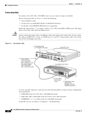
... router installation: • LINK LED on the Cisco 801, 802, or 802 IDSL back panel. • LKØ, LK1, LK2, or LK3 LED on the Cisco 803 or Cisco 804 front panel. • ETHERNET 1, 2, 3, or 4 LED on the Cisco 804 IDSL front panel. Caution Always connect the yellow cable or an Ethernet cable to an NT1. HUB NO HUB ETHERNET 10 BASE T 0 1 2 3 Cisco 803 CONSOLE ISDN S/T PHONE 1 2 Cisco Micro Hub 10/100 11674 1X 101S00PBBEaasEseeDTTX LED SOLID BLINK 1 5 2 6 3 7 4 8 2X ETHERNET...
... router installation: • LINK LED on the Cisco 801, 802, or 802 IDSL back panel. • LKØ, LK1, LK2, or LK3 LED on the Cisco 803 or Cisco 804 front panel. • ETHERNET 1, 2, 3, or 4 LED on the Cisco 804 IDSL front panel. Caution Always connect the yellow cable or an Ethernet cable to an NT1. HUB NO HUB ETHERNET 10 BASE T 0 1 2 3 Cisco 803 CONSOLE ISDN S/T PHONE 1 2 Cisco Micro Hub 10/100 11674 1X 101S00PBBEaasEseeDTTX LED SOLID BLINK 1 5 2 6 3 7 4 8 2X ETHERNET...
Hardware Installation Guide
Page 31
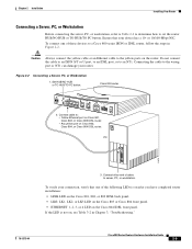
... button. Cisco 803 router HUB NO HUB ETHERNET 10 BASE T 0 1 2 3 Cisco 803 CONSOLE ISDN S/T PHONE 1 2 2. Chapter 2 Installation Installing Your Router Connecting a Server, PC, or Workstation Before connecting the server, PC, or workstation, refer to Table 2-2 to determine how to an NT1. Ensure that one of cable to the yellow ports on the Cisco 804 IDSL front panel. Connect other end of these devices to : • Yellow Ethernet port on Cisco 801, Cisco 802, or Cisco 802 IDSL router. • Any yellow port...
... button. Cisco 803 router HUB NO HUB ETHERNET 10 BASE T 0 1 2 3 Cisco 803 CONSOLE ISDN S/T PHONE 1 2 2. Chapter 2 Installation Installing Your Router Connecting a Server, PC, or Workstation Before connecting the server, PC, or workstation, refer to Table 2-2 to determine how to an NT1. Ensure that one of cable to the yellow ports on the Cisco 804 IDSL front panel. Connect other end of these devices to : • Yellow Ethernet port on Cisco 801, Cisco 802, or Cisco 802 IDSL router. • Any yellow port...
Hardware Installation Guide
Page 42
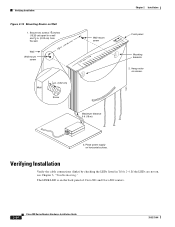
.... (0.32 cm) from the wall. 758 in. (19.35 cm) Wall Wall-mount screw Wall-mount screw Wall 1 8 in Table 2-4. Hang router on horizontal surface. Place power supply on screws. 3. If the LEDs are not on the back panel of Cisco 801 and Cisco 802 routers. 2-20 Cisco 800 Series Routers Hardware Installation Guide 78-5373-04 The LINK LED is on , see Chapter 3, "Troubleshooting." Verifying Installation Figure 2-12 Mounting Router on Wall 1.
.... (0.32 cm) from the wall. 758 in. (19.35 cm) Wall Wall-mount screw Wall-mount screw Wall 1 8 in Table 2-4. Hang router on horizontal surface. Place power supply on screws. 3. If the LEDs are not on the back panel of Cisco 801 and Cisco 802 routers. 2-20 Cisco 800 Series Routers Hardware Installation Guide 78-5373-04 The LINK LED is on , see Chapter 3, "Troubleshooting." Verifying Installation Figure 2-12 Mounting Router on Wall 1.

Hardware Installation Guide
Page 47
... Table 2-2 in Chapter 2, "Installation." • Check specifications in Table B-13 and Table B-14 in Appendix B, "Specifications and Cables," to Cisco 801 and Cisco 803 Routers" section in Chapter 2, "Installation." 78-5373-04 Cisco 800 Series Routers Hardware Installation Guide 3-3 Improperly connected cable. - If it does not, replace it is not physically damaged. Chapter 3 Troubleshooting Problems After First Startup Problems After First Startup Table 3-2 lists problems that connects the NT1 to an Ethernet device. (On Cisco 801, Cisco 802, and 802 IDSL routers, the LINK LED...
... Table 2-2 in Chapter 2, "Installation." • Check specifications in Table B-13 and Table B-14 in Appendix B, "Specifications and Cables," to Cisco 801 and Cisco 803 Routers" section in Chapter 2, "Installation." 78-5373-04 Cisco 800 Series Routers Hardware Installation Guide 3-3 Improperly connected cable. - If it does not, replace it is not physically damaged. Chapter 3 Troubleshooting Problems After First Startup Problems After First Startup Table 3-2 lists problems that connects the NT1 to an Ethernet device. (On Cisco 801, Cisco 802, and 802 IDSL routers, the LINK LED...

Hardware Installation Guide
Page 48
... or Internet service provider to determine if there is , replace it . Damaged cable. Analog Telephone, Fax, or Modem" section - Cisco 800 Series Routers Hardware Installation Guide 3-4 78-5373-04 sections in Chapter 2, "Installation." • Make sure the connectors at both ends of each cable are securely connected. • Make sure each cable is not physically damaged. If it is a problem with ISDN or IDSL line. • Contact your Cisco reseller...
... or Internet service provider to determine if there is , replace it . Damaged cable. Analog Telephone, Fax, or Modem" section - Cisco 800 Series Routers Hardware Installation Guide 3-4 78-5373-04 sections in Chapter 2, "Installation." • Make sure the connectors at both ends of each cable are securely connected. • Make sure each cable is not physically damaged. If it is a problem with ISDN or IDSL line. • Contact your Cisco reseller...

Hardware Installation Guide
Page 49
... telephone service provider to determine if it . 78-5373-04 Cisco 800 Series Routers Hardware Installation Guide 3-5 On the Cisco 804 IDSL router, the ETHERNET 1, 2, 3, or 4 LED on the front panel blinks.) • One of the cable are securely connected. • Make sure the cable is off . Disconnected cable. - Perform the following tasks in the following cable-related problems: - If it is not, replace it is not physically damaged. Problems After Router Is Running Table 3-3 lists problems that...
... telephone service provider to determine if it . 78-5373-04 Cisco 800 Series Routers Hardware Installation Guide 3-5 On the Cisco 804 IDSL router, the ETHERNET 1, 2, 3, or 4 LED on the front panel blinks.) • One of the cable are securely connected. • Make sure the cable is off . Disconnected cable. - Perform the following tasks in the following cable-related problems: - If it is not, replace it is not physically damaged. Problems After Router Is Running Table 3-3 lists problems that...

Hardware Installation Guide
Page 51
...; Router model and serial number (see the back panel of the solutions instruct you received your telephone company to line. Chapter 3 Troubleshooting When Contacting Your Cisco Reseller Table 3-3 Problems After Router Is Running (continued) Symptom Connection to analog telephone, fax machine, or modem is lost. (PH1 or PH2 LED on Cisco 803 and 804 routers is off.) Problem Solutions • If the problem continues, call your Cisco reseller. • A cable-related problem: •...
...; Router model and serial number (see the back panel of the solutions instruct you received your telephone company to line. Chapter 3 Troubleshooting When Contacting Your Cisco Reseller Table 3-3 Problems After Router Is Running (continued) Symptom Connection to analog telephone, fax machine, or modem is lost. (PH1 or PH2 LED on Cisco 803 and 804 routers is off.) Problem Solutions • If the problem continues, call your Cisco reseller. • A cable-related problem: •...
Hardware Installation Guide
Page 69
Index S S/T interface A-1 safety warnings 2-2 server, connecting 2-9 settings, network devices 2-6 to 2-7 specifications cabling B-6 system B-1 startup problems 3-2 T table mounting 2-18 telephone connecting 2-14, 2-15 ports described 1-2 illustrated 1-5, 1-6 temperature specifications B-1 terminal, connecting 2-17 TO HUB/TO PC button illustrated 1-6 to 1-7 settings 2-6 to 2-20 warnings, installation 2-2 weight specifications B-1 workstation, connecting 2-9 U U interface A-1 United Kingdom master sockets 2-16 78-5373-04 Cisco 800 Series Routers Hardware Installation Guide IN-3 to 2-4 V...
Index S S/T interface A-1 safety warnings 2-2 server, connecting 2-9 settings, network devices 2-6 to 2-7 specifications cabling B-6 system B-1 startup problems 3-2 T table mounting 2-18 telephone connecting 2-14, 2-15 ports described 1-2 illustrated 1-5, 1-6 temperature specifications B-1 terminal, connecting 2-17 TO HUB/TO PC button illustrated 1-6 to 1-7 settings 2-6 to 2-20 warnings, installation 2-2 weight specifications B-1 workstation, connecting 2-9 U U interface A-1 United Kingdom master sockets 2-16 78-5373-04 Cisco 800 Series Routers Hardware Installation Guide IN-3 to 2-4 V...


