Installation Guide
Page 2
..."AS IS" WITH ALL FAULTS. The following information is no longer complying with FCC requirements for a Class B digital device in accordance with the specifications in a commercial environment. However, there is for a Class A digital device, pursuant to this product not authorized by FCC regulations, and you ...DAMAGE TO DATA ARISING OUT OF THE USE OR INABILITY TO USE THIS MANUAL, EVEN IF CISCO OR ITS SUPPLIERS HAVE BEEN ADVISED OF THE POSSIBILITY OF SUCH DAMAGES. THE SPECIFICATIONS AND INFORMATION REGARDING THE PRODUCTS IN THIS MANUAL ARE SUBJECT TO CHANGE WITHOUT NOTICE. USERS MUST...
..."AS IS" WITH ALL FAULTS. The following information is no longer complying with FCC requirements for a Class B digital device in accordance with the specifications in a commercial environment. However, there is for a Class A digital device, pursuant to this product not authorized by FCC regulations, and you ...DAMAGE TO DATA ARISING OUT OF THE USE OR INABILITY TO USE THIS MANUAL, EVEN IF CISCO OR ITS SUPPLIERS HAVE BEEN ADVISED OF THE POSSIBILITY OF SUCH DAMAGES. THE SPECIFICATIONS AND INFORMATION REGARDING THE PRODUCTS IN THIS MANUAL ARE SUBJECT TO CHANGE WITHOUT NOTICE. USERS MUST...
Installation Guide
Page 6
... Indicators 2-1 Upgrading the Memory 2-3 Installing the IDS-4210 2-5 Installing the Accessories 2-8 Accessories Package Contents 2-8 Installing and Removing the Bezel 2-9 Installing Center Mount Brackets 2-9 Installing Front Mount Brackets 2-11 Installing the IDS-4215 3-1 Front and Back Panel Features 3-2 Specifications 3-4 Accessories 3-5 Surface Mounting 3-6 Rack Mounting 3-7 Installing the IDS-4215 3-9 Cisco Intrusion Detection System Appliance and Module Installation and Configuration...
... Indicators 2-1 Upgrading the Memory 2-3 Installing the IDS-4210 2-5 Installing the Accessories 2-8 Accessories Package Contents 2-8 Installing and Removing the Bezel 2-9 Installing Center Mount Brackets 2-9 Installing Front Mount Brackets 2-11 Installing the IDS-4215 3-1 Front and Back Panel Features 3-2 Specifications 3-4 Accessories 3-5 Surface Mounting 3-6 Rack Mounting 3-7 Installing the IDS-4215 3-9 Cisco Intrusion Detection System Appliance and Module Installation and Configuration...
Installation Guide
Page 7
... and Monitors 4-4 Upgrading the IDS-4220-E and IDS-4230-FE to 4.x Software 4-5 Installing the IDS-4220 and IDS-4230 4-6 Installing the IDS-4235 and IDS-4250 5-1 Front-Panel Features and Indicators 5-2 Back-Panel Features and Indicators 5-4 Specifications 5-5 Installing Spare Hard-Disk Drives 5-6 Upgrading the BIOS 5-7 Using the TCP Reset Interface 5-8 Installing the IDS-4235 and IDS-4250 5-9 Cisco Intrusion Detection System Appliance and Module Installation...
... and Monitors 4-4 Upgrading the IDS-4220-E and IDS-4230-FE to 4.x Software 4-5 Installing the IDS-4220 and IDS-4230 4-6 Installing the IDS-4235 and IDS-4250 5-1 Front-Panel Features and Indicators 5-2 Back-Panel Features and Indicators 5-4 Specifications 5-5 Installing Spare Hard-Disk Drives 5-6 Upgrading the BIOS 5-7 Using the TCP Reset Interface 5-8 Installing the IDS-4235 and IDS-4250 5-9 Cisco Intrusion Detection System Appliance and Module Installation...
Installation Guide
Page 8
... 5-35 Marking the Rack 5-35 Installing the Slide Assemblies in the Rack 5-36 Installing the IPS-4240 and IPS-4255 6-1 Front and Back Panel Features 6-2 Specifications 6-5 Accessories 6-6 Rack Mounting 6-7 Installing the IPS-4240 and IPS-4255 6-9 Cisco Intrusion Detection System Appliance and Module Installation and Configuration Guide Version 4.1 viii 78-15597-02
... 5-35 Marking the Rack 5-35 Installing the Slide Assemblies in the Rack 5-36 Installing the IPS-4240 and IPS-4255 6-1 Front and Back Panel Features 6-2 Specifications 6-5 Accessories 6-6 Rack Mounting 6-7 Installing the IPS-4240 and IPS-4255 6-9 Cisco Intrusion Detection System Appliance and Module Installation and Configuration Guide Version 4.1 viii 78-15597-02
Installation Guide
Page 9
... C H A P T E R 8 C H A P T E R Installing the NM-CIDS 7-1 Specifications 7-1 Software and Hardware Requirements 7-2 Hardware Architecture 7-4 Front Panel Features 7-5 Interfaces 7-5 Installation and Removal Instructions 7-6 Required... 8-1 Specifications 8-1 Software and Hardware Requirements 8-2 Supported IDSM-2 Configurations 8-3 Using the TCP Reset Interface 8-4 Front Panel Description 8-4 Installation and Removal Instructions 8-5 Required Tools 8-6 Slot Assignments 8-6 Installing the IDSM-2 8-7 Verifying the IDSM-2 Installation 8-11 Removing the IDSM-2 8-13 Cisco Intrusion Detection System ...
... C H A P T E R 8 C H A P T E R Installing the NM-CIDS 7-1 Specifications 7-1 Software and Hardware Requirements 7-2 Hardware Architecture 7-4 Front Panel Features 7-5 Interfaces 7-5 Installation and Removal Instructions 7-6 Required... 8-1 Specifications 8-1 Software and Hardware Requirements 8-2 Supported IDSM-2 Configurations 8-3 Using the TCP Reset Interface 8-4 Front Panel Description 8-4 Installation and Removal Instructions 8-5 Required Tools 8-6 Slot Assignments 8-6 Installing the IDSM-2 8-7 Verifying the IDSM-2 Installation 8-11 Removing the IDSM-2 8-13 Cisco Intrusion Detection System ...

Installation Guide
Page 11
...37 Viewing Signature Engine Parameters 10-39 Configuring Virtual Sensor System Variables 10-42 Tuning Signature Engines 10-45 IP Logging 10-50 Manual IP Logging for a Specific IP Address 10-51 Automatic IP Logging for a Specific Signature 10-53 Disabling IP Logging 10-55 ...10-76 NM-CIDS Configuration Tasks 10-77 Configuring Cisco IDS Interfaces on the Router 10-78 Establishing Cisco IDS Console Sessions 10-80 Using the Session Command 10-80 Suspending a Session and Returning to the Router 10-81 Cisco Intrusion Detection System Appliance and Module Installation and Configuration Guide Version...
...37 Viewing Signature Engine Parameters 10-39 Configuring Virtual Sensor System Variables 10-42 Tuning Signature Engines 10-45 IP Logging 10-50 Manual IP Logging for a Specific IP Address 10-51 Automatic IP Logging for a Specific Signature 10-53 Disabling IP Logging 10-55 ...10-76 NM-CIDS Configuration Tasks 10-77 Configuring Cisco IDS Interfaces on the Router 10-78 Establishing Cisco IDS Console Sessions 10-80 Using the Session Command 10-80 Suspending a Session and Returning to the Router 10-81 Cisco Intrusion Detection System Appliance and Module Installation and Configuration Guide Version...
Installation Guide
Page 25
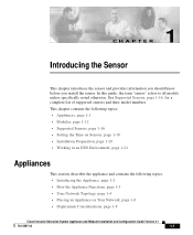
...R 1 Introducing the Sensor This chapter introduces the sensor and provides information you should know before you install the sensor. See Supported Sensors, page 1-16, for a complete list of supported sensors and their model numbers. In this guide, the term "sensor" refers to all models unless specifically noted otherwise. This chapter... Your Network Topology, page 1-4 • Placing an Appliance on Your Network, page 1-6 • Deployment Considerations, page 1-8 Cisco Intrusion Detection System Appliance and Module Installation and Configuration Guide Version 4.1 78-15597-02 1-1
...R 1 Introducing the Sensor This chapter introduces the sensor and provides information you should know before you install the sensor. See Supported Sensors, page 1-16, for a complete list of supported sensors and their model numbers. In this guide, the term "sensor" refers to all models unless specifically noted otherwise. This chapter... Your Network Topology, page 1-4 • Placing an Appliance on Your Network, page 1-6 • Deployment Considerations, page 1-8 Cisco Intrusion Detection System Appliance and Module Installation and Configuration Guide Version 4.1 78-15597-02 1-1
Installation Guide
Page 26
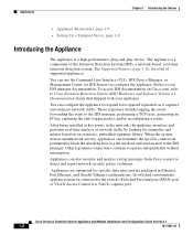
... port. See Supported Sensors, page 1-16, for anomalies and misuse based on Cisco.com, refer to your appliance. After being installed at key points in Ethernet, Fast Ethernet, and Gigabit Ethernet configurations. Refer to Cisco Intrusion Detection System (IDS) Hardware and Software ... independently without interruption. Cisco Intrusion Detection System Appliance and Module Installation and Configuration Guide Version 4.1 1-2 78-15597-02 To access IDS documentation on an extensive, embedded signature library. You can terminate the specific connection, permanently block ...
... port. See Supported Sensors, page 1-16, for anomalies and misuse based on Cisco.com, refer to your appliance. After being installed at key points in Ethernet, Fast Ethernet, and Gigabit Ethernet configurations. Refer to Cisco Intrusion Detection System (IDS) Hardware and Software ... independently without interruption. Cisco Intrusion Detection System Appliance and Module Installation and Configuration Guide Version 4.1 1-2 78-15597-02 To access IDS documentation on an extensive, embedded signature library. You can terminate the specific connection, permanently block ...
Installation Guide
Page 29
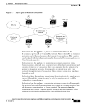
Chapter 1 Introducing the Sensor Appliances Figure 1-1 Major Types of a remote access server. This ...of one , the appliance is placed to monitor traffic between the E-commerce (protected) network and the Internet. Cisco Intrusion Detection System Appliance and Module Installation and Configuration Guide Version 4.1 78-15597-02 1-5 In location two, the appliance ...types described so far are required. These extranet connections may contain company-specific research and development or other engineering information and should be vulnerable to as well. This is referred to...
Chapter 1 Introducing the Sensor Appliances Figure 1-1 Major Types of a remote access server. This ...of one , the appliance is placed to monitor traffic between the E-commerce (protected) network and the Internet. Cisco Intrusion Detection System Appliance and Module Installation and Configuration Guide Version 4.1 78-15597-02 1-5 In location two, the appliance ...types described so far are required. These extranet connections may contain company-specific research and development or other engineering information and should be vulnerable to as well. This is referred to...

Installation Guide
Page 61
...; Specifications, page 3-4 • Accessories, page 3-5 • Surface Mounting, page 3-6 • Rack Mounting, page 3-7 • Installing the IDS-4215, page 3-9 • Removing and Replacing the Chassis Cover, page 3-12 Cisco Intrusion Detection System Appliance and Module Installation and Configuration Guide Version 4.1 78-15597-02 3-1 This chapter contains the following conditions: aggregation of 445 bytes, system running Cisco IDS 4.1 sensor...
...; Specifications, page 3-4 • Accessories, page 3-5 • Surface Mounting, page 3-6 • Rack Mounting, page 3-7 • Installing the IDS-4215, page 3-9 • Removing and Replacing the Chassis Cover, page 3-12 Cisco Intrusion Detection System Appliance and Module Installation and Configuration Guide Version 4.1 78-15597-02 3-1 This chapter contains the following conditions: aggregation of 445 bytes, system running Cisco IDS 4.1 sensor...
Installation Guide
Page 64
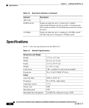
... 60 Hz, single phase 1.5 A 50W 65W 410 BTU/hr, full power usage (65W) Cisco Intrusion Detection System Appliance and Module Installation and Configuration Guide Version 4.1 3-4 78-15597-02 off when Ethernet packets are being passed between them; Specifications Chapter 3 Installing the IDS-4215 Table 3-2 Back Panel Indicators (continued) Indicator 4FE Card LINK/activity 100 Mbps Description...
... 60 Hz, single phase 1.5 A 50W 65W 410 BTU/hr, full power usage (65W) Cisco Intrusion Detection System Appliance and Module Installation and Configuration Guide Version 4.1 3-4 78-15597-02 off when Ethernet packets are being passed between them; Specifications Chapter 3 Installing the IDS-4215 Table 3-2 Back Panel Indicators (continued) Indicator 4FE Card LINK/activity 100 Mbps Description...
Installation Guide
Page 65
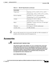
Chapter 3 Installing the IDS-4215 Accessories Table 3-3 IDS-4215 Specifications (continued) Environment Temperature Relative humidity Altitude Shock Vibration Acoustic noise Operating +41°F to +104°F (+5°C to +40°C) Nonoperating -...aware of each warning to 15,000 ft (4750 m) Operating 1.14 m/sec (45 in a situation that accompanied this device. Statement 1071 SAVE THESE INSTRUCTIONS Cisco Intrusion Detection System Appliance and Module Installation and Configuration Guide Version 4.1 78-15597-02 3-5 You are in ./sec) 1/2 sine input Nonoperating 30 G 0.41 Grms2 (3-...
Chapter 3 Installing the IDS-4215 Accessories Table 3-3 IDS-4215 Specifications (continued) Environment Temperature Relative humidity Altitude Shock Vibration Acoustic noise Operating +41°F to +104°F (+5°C to +40°C) Nonoperating -...aware of each warning to 15,000 ft (4750 m) Operating 1.14 m/sec (45 in a situation that accompanied this device. Statement 1071 SAVE THESE INSTRUCTIONS Cisco Intrusion Detection System Appliance and Module Installation and Configuration Guide Version 4.1 78-15597-02 3-5 You are in ./sec) 1/2 sine input Nonoperating 30 G 0.41 Grms2 (3-...
Installation Guide
Page 100
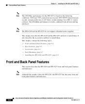
...IDS-4250 is based on the front panel of the IDS-4235 and IDS-4250. Cisco Intrusion Detection System Appliance and Module Installation and Configuration Guide Version 4.1 5-2 78-15597-02 Or you can order the IDS... Specifications, page 5-5 • Installing Spare Hard-Disk Drives, page 5-6 • Upgrading the BIOS, page 5-7 • Using the TCP Reset Interface, page 5-8 • Installing the IDS-4235 and IDS-4250... Cisco IDS 4.1 sensor software. Front-Panel Features and Indicators Chapter 5 Installing the IDS-4235 and IDS-4250 Note The 500-Mbps performance for the IDS-4250...
...IDS-4250 is based on the front panel of the IDS-4235 and IDS-4250. Cisco Intrusion Detection System Appliance and Module Installation and Configuration Guide Version 4.1 5-2 78-15597-02 Or you can order the IDS... Specifications, page 5-5 • Installing Spare Hard-Disk Drives, page 5-6 • Upgrading the BIOS, page 5-7 • Using the TCP Reset Interface, page 5-8 • Installing the IDS-4235 and IDS-4250... Cisco IDS 4.1 sensor software. Front-Panel Features and Indicators Chapter 5 Installing the IDS-4235 and IDS-4250 Note The 500-Mbps performance for the IDS-4250...
Installation Guide
Page 103
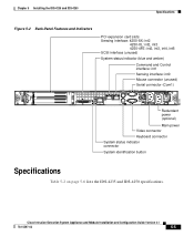
Chapter 5 Installing the IDS-4235 and IDS-4250 Specifications Figure 5-2 Back-Panel Features and Indicators PCI expansion card slots Sensing interface: 4250-SX: int2 4250-XL: int2, int3 4250-4FE: int2,... connector (unused) Serial connector (Com1) Redundant power (optional) Main power Video connector Keyboard connector System status indicator connector System identification button Specifications Table 5-2 on page 5-6 lists the IDS-4235 and IDS-4250 specifications. 83724 Cisco Intrusion Detection System Appliance and Module Installation and Configuration Guide Version 4.1 78-15597-02 5-5
Chapter 5 Installing the IDS-4235 and IDS-4250 Specifications Figure 5-2 Back-Panel Features and Indicators PCI expansion card slots Sensing interface: 4250-SX: int2 4250-XL: int2, int3 4250-4FE: int2,... connector (unused) Serial connector (Com1) Redundant power (optional) Main power Video connector Keyboard connector System status indicator connector System identification button Specifications Table 5-2 on page 5-6 lists the IDS-4235 and IDS-4250 specifications. 83724 Cisco Intrusion Detection System Appliance and Module Installation and Configuration Guide Version 4.1 78-15597-02 5-5
Installation Guide
Page 104
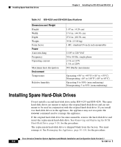
...conjunction with the original hard-disk drive. Installing Spare Hard-Disk Drives Chapter 5 Installing the IDS-4235 and IDS-4250 Table 5-2 IDS-4235 and IDS-4250 Specifications Dimensions and Weight Height Width Depth Weight Form factor Power Autoswitching Frequency Operating current Maximum heat ...page 5-20, for the procedure. See Reimaging the Appliance, page 10-110, for the procedure. You must reimage it. Cisco Intrusion Detection System Appliance and Module Installation and Configuration Guide Version 4.1 5-6 78-15597-02 The replacement hard-disk drive is shipped blank ...
...conjunction with the original hard-disk drive. Installing Spare Hard-Disk Drives Chapter 5 Installing the IDS-4235 and IDS-4250 Table 5-2 IDS-4235 and IDS-4250 Specifications Dimensions and Weight Height Width Depth Weight Form factor Power Autoswitching Frequency Operating current Maximum heat ...page 5-20, for the procedure. See Reimaging the Appliance, page 10-110, for the procedure. You must reimage it. Cisco Intrusion Detection System Appliance and Module Installation and Configuration Guide Version 4.1 5-6 78-15597-02 The replacement hard-disk drive is shipped blank ...
Installation Guide
Page 106
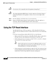
... all the VLANs being trunked by both the sensing ports. Cisco Intrusion Detection System Appliance and Module Installation and Configuration Guide Version 4.1 5-8 78-15597-02 Using the TCP Reset Interface Chapter 5 Installing the IDS-4235 and IDS-4250 Caution Do not power off or manually reboot the appliance... appliance while the appliance is connected to be started again. Remove the BIOS update diskette from a console connection. The IDS-4250-XL has a specific TCP reset interface because it cannot send TCP resets on -screen instructions. You must connect a keyboard and monitor to ...
... all the VLANs being trunked by both the sensing ports. Cisco Intrusion Detection System Appliance and Module Installation and Configuration Guide Version 4.1 5-8 78-15597-02 Using the TCP Reset Interface Chapter 5 Installing the IDS-4235 and IDS-4250 Caution Do not power off or manually reboot the appliance... appliance while the appliance is connected to be started again. Remove the BIOS update diskette from a console connection. The IDS-4250-XL has a specific TCP reset interface because it cannot send TCP resets on -screen instructions. You must connect a keyboard and monitor to ...
Installation Guide
Page 142
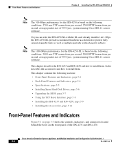
Cisco Intrusion Detection System Appliance and Module Installation and Configuration Guide Version 4.1 6-2 78-15597-02 This chapter contains the following conditions: 6000 new TCP connections per second, 6000 HTTP transactions per second, average packet size of 445 bytes, system running Cisco IDS 4.1 sensor ...power supplies. The 600-Mbps performance is based on the following topics: • Front and Back Panel Features, page 6-2 • Specifications, page 6-5 • Accessories, page 6-6 • Rack Mounting, page 6-7 • Installing the IPS-4240 and IPS-4255, page...
Cisco Intrusion Detection System Appliance and Module Installation and Configuration Guide Version 4.1 6-2 78-15597-02 This chapter contains the following conditions: 6000 new TCP connections per second, 6000 HTTP transactions per second, average packet size of 445 bytes, system running Cisco IDS 4.1 sensor ...power supplies. The 600-Mbps performance is based on the following topics: • Front and Back Panel Features, page 6-2 • Specifications, page 6-5 • Accessories, page 6-6 • Rack Mounting, page 6-7 • Installing the IPS-4240 and IPS-4255, page...
Installation Guide
Page 145
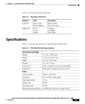
... state 50 W Maximum peak 65 W Maximum heat dissipation 410 BTU/hr, full power usage (65 W) Cisco Intrusion Detection System Appliance and Module Installation and Configuration Guide Version 4.1 78-15597-02 6-5 Chapter 6 Installing the IPS-4240 and IPS-4255 Specifications Table 6-2 lists the back panel indicators. Table 6-2 Back Panel Indicators Indicator Left side Right side...
... state 50 W Maximum peak 65 W Maximum heat dissipation 410 BTU/hr, full power usage (65 W) Cisco Intrusion Detection System Appliance and Module Installation and Configuration Guide Version 4.1 78-15597-02 6-5 Chapter 6 Installing the IPS-4240 and IPS-4255 Specifications Table 6-2 lists the back panel indicators. Table 6-2 Back Panel Indicators Indicator Left side Right side...
Installation Guide
Page 146
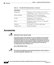
... in the translated safety warnings that could cause bodily injury. Statement 1030 Cisco Intrusion Detection System Appliance and Module Installation and Configuration Guide Version 4.1 6-6 78-15597-02 Accessories Chapter 6 Installing the IPS-4240 and IPS-4255 Table 6-3 IPS-4240/IPS-4255 Specifications (continued) Environment Temperature Relative humidity Altitude Shock Vibration Acoustic noise Operating +32...
... in the translated safety warnings that could cause bodily injury. Statement 1030 Cisco Intrusion Detection System Appliance and Module Installation and Configuration Guide Version 4.1 6-6 78-15597-02 Accessories Chapter 6 Installing the IPS-4240 and IPS-4255 Table 6-3 IPS-4240/IPS-4255 Specifications (continued) Environment Temperature Relative humidity Altitude Shock Vibration Acoustic noise Operating +32...
Installation Guide
Page 153
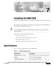
... the NM-CIDS. Table 7-1 NM-CIDS Specifications Specification Dimensions (H x W x D) Weight Operating temperature Description 1.55 x 7.10 x 7.2 in. (3.9 x 18.0 x 19.3 cm) 1.5 lb (0.7 kg) (maximum) 32° to 104°F (0° to as the Cisco IDS network module. Note In Cisco IOS documentation, the NM-CIDS is referred to 40°C) Cisco Intrusion Detection System Appliance and Module Installation and Configuration...
... the NM-CIDS. Table 7-1 NM-CIDS Specifications Specification Dimensions (H x W x D) Weight Operating temperature Description 1.55 x 7.10 x 7.2 in. (3.9 x 18.0 x 19.3 cm) 1.5 lb (0.7 kg) (maximum) 32° to 104°F (0° to as the Cisco IDS network module. Note In Cisco IOS documentation, the NM-CIDS is referred to 40°C) Cisco Intrusion Detection System Appliance and Module Installation and Configuration...