
Installation Guide
Page 3
... H A P T E R OL-13017-01 CONTENTS Preface ix Audience ix Purpose ix Conventions ix Related Publications x Obtaining Documentation, Obtaining Support, and Security Guidelines x Overview 1-1 Overview 1-1 Switch Models 1-2 Front-Panel Description 1-2 10/100 Ports 1-5 Dual-Purpose Ports 1-5 100BASE-FX Ports 1-5 Power and Relay Connector 1-5 Console Port 1-6 LEDs 1-6 Setup LED ... Description 1-12 Power Converter (Optional) 1-13 Management Options 1-14 Network Configurations 1-15 Switch Installation 2-1 Preparing for Installation 2-1 Warnings 2-2 Cisco IE 3000 Switch Hardware Installation Guide iii
... H A P T E R OL-13017-01 CONTENTS Preface ix Audience ix Purpose ix Conventions ix Related Publications x Obtaining Documentation, Obtaining Support, and Security Guidelines x Overview 1-1 Overview 1-1 Switch Models 1-2 Front-Panel Description 1-2 10/100 Ports 1-5 Dual-Purpose Ports 1-5 100BASE-FX Ports 1-5 Power and Relay Connector 1-5 Console Port 1-6 LEDs 1-6 Setup LED ... Description 1-12 Power Converter (Optional) 1-13 Management Options 1-14 Network Configurations 1-15 Switch Installation 2-1 Preparing for Installation 2-1 Warnings 2-2 Cisco IE 3000 Switch Hardware Installation Guide iii
Installation Guide
Page 11
... • Rear-Panel Description, page 1-12 • Power Converter (Optional), page 1-13 • Management Options, page 1-14 • Network Configurations, page 1-15 Overview The Cisco IE 3000 switch provides a rugged and secure switching infrastructure for industrial Ethernet applications, including factory automation, intelligent transportation systems (ITSs), substations, and other deployments in harsh environments. In industrial environments, you...
... • Rear-Panel Description, page 1-12 • Power Converter (Optional), page 1-13 • Management Options, page 1-14 • Network Configurations, page 1-15 Overview The Cisco IE 3000 switch provides a rugged and secure switching infrastructure for industrial Ethernet applications, including factory automation, intelligent transportation systems (ITSs), substations, and other deployments in harsh environments. In industrial environments, you...

Installation Guide
Page 12
.... Cisco IE 3000 Switch Hardware Installation Guide 1-2 OL-13017-01 Switch Models Chapter 1 Overview Switch Models Table 1-1 describes the switch and the expansion modules. For instructions on how to connect the expansion modules to the switch, see the "Adding Modules to Figure 1-4 show the switch and expansion module front panels. The Cisco IE-3000-4TC and the Cisco IE-3000-8TC are the switch models, and the Cisco IEM-3000...
.... Cisco IE 3000 Switch Hardware Installation Guide 1-2 OL-13017-01 Switch Models Chapter 1 Overview Switch Models Table 1-1 describes the switch and the expansion modules. For instructions on how to connect the expansion modules to the switch, see the "Adding Modules to Figure 1-4 show the switch and expansion module front panels. The Cisco IE-3000-4TC and the Cisco IE-3000-8TC are the switch models, and the Cisco IEM-3000...

Installation Guide
Page 13
Chapter 1 Overview Figure 1-1 Cisco IE-3000-8TC Switch 1 2 Front-Panel Description 201699 3 45 1 Power and relay connectors 4 10/100 ports 2 Console port 5 Protective ground connection 3 Dual-purpose ports Figure 1-2 Cisco IE-3000-4TC Switch 1 2 201700 3 45 1 Power and relay connectors 4 2 Console port 5 3 Dual-purpose ports 10/100 ports Protective ground connection OL-13017-01 Cisco IE 3000 Switch Hardware Installation Guide 1-3
Chapter 1 Overview Figure 1-1 Cisco IE-3000-8TC Switch 1 2 Front-Panel Description 201699 3 45 1 Power and relay connectors 4 10/100 ports 2 Console port 5 Protective ground connection 3 Dual-purpose ports Figure 1-2 Cisco IE-3000-4TC Switch 1 2 201700 3 45 1 Power and relay connectors 4 2 Console port 5 3 Dual-purpose ports 10/100 ports Protective ground connection OL-13017-01 Cisco IE 3000 Switch Hardware Installation Guide 1-3

Installation Guide
Page 15
... Connector You connect the DC power and alarm signals to the switch through cable. See Figure 1-2. OL-13017-01 Cisco IE 3000 Switch Hardware Installation Guide 1-5 If the connected device also supports autonegotiation, the switch port negotiates the best connection (that the cable is autonegotiate.) When...switch software. 100BASE-FX Ports The IEEE 802.3u 100BASE-FX ports provide full-duplex 100 Mb/s connectivity over multimode fiber (MMF) cables. You use fiber-optic cables with IEEE 802.3AB. (The default setting is a straight-through two front panel connectors. Chapter 1 Overview...
... Connector You connect the DC power and alarm signals to the switch through cable. See Figure 1-2. OL-13017-01 Cisco IE 3000 Switch Hardware Installation Guide 1-5 If the connected device also supports autonegotiation, the switch port negotiates the best connection (that the cable is autonegotiate.) When...switch software. 100BASE-FX Ports The IEEE 802.3u 100BASE-FX ports provide full-duplex 100 Mb/s connectivity over multimode fiber (MMF) cables. You use fiber-optic cables with IEEE 802.3AB. (The default setting is a straight-through two front panel connectors. Chapter 1 Overview...

Installation Guide
Page 16
... Cable Pinouts" section on the power and relay connector are visible through the console port and the supplied RJ-45-to polarity. Cisco IE 3000 Switch Hardware Installation Guide 1-6 OL-13017-01 When both alarm relays. If one or with one of the two power sources fail, the...1-9 show the front panel LEDs, and the following sections describe them without regard to -DB-9 adapter cable. Front-Panel Description Chapter 1 Overview The switch accessory pack includes the mating power and relay connectors. You can connect them . All LEDs are labeled A, and you can use the CLI...
... Cable Pinouts" section on the power and relay connector are visible through the console port and the supplied RJ-45-to polarity. Cisco IE 3000 Switch Hardware Installation Guide 1-6 OL-13017-01 When both alarm relays. If one or with one of the two power sources fail, the...1-9 show the front panel LEDs, and the following sections describe them without regard to -DB-9 adapter cable. Front-Panel Description Chapter 1 Overview The switch accessory pack includes the mating power and relay connectors. You can connect them . All LEDs are labeled A, and you can use the CLI...
Installation Guide
Page 17
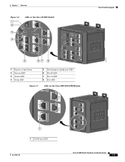
Chapter 1 Overview Figure 1-6 1 2 3 4 LEDs on the Cisco IE 3000 Switch Front-Panel Description 201703 5 67 8 1 Express setup button 2 System LED 3 Alarm LED 4 Setup LED 5 Dual-purpose uplink port LED 6 Pwr B LED 7 Pwr A LED 8 Port LED Figure 1-7 LEDs on the Cisco IEM-3000-8TM Module 201706 1 1 10/100 port LED OL-13017-01 Cisco IE 3000 Switch Hardware Installation Guide 1-7
Chapter 1 Overview Figure 1-6 1 2 3 4 LEDs on the Cisco IE 3000 Switch Front-Panel Description 201703 5 67 8 1 Express setup button 2 System LED 3 Alarm LED 4 Setup LED 5 Dual-purpose uplink port LED 6 Pwr B LED 7 Pwr A LED 8 Port LED Figure 1-7 LEDs on the Cisco IEM-3000-8TM Module 201706 1 1 10/100 port LED OL-13017-01 Cisco IE 3000 Switch Hardware Installation Guide 1-7
Installation Guide
Page 18
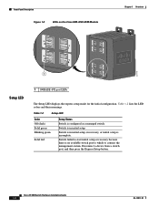
...-Panel Description Figure 1-8 LEDs on the Cisco IEM-3000-8FM Module Chapter 1 Overview 201705 1 Setup LED 1 100BASE -FX port LEDs The Setup LED displays the express setup mode for the initial configuration. Table 1-2 Setup LED Color Off (dark) Solid green Blinking green Solid red Setup Status Switch is incomplete. Cisco IE 3000 Switch Hardware Installation Guide 1-8 OL-13017...
...-Panel Description Figure 1-8 LEDs on the Cisco IEM-3000-8FM Module Chapter 1 Overview 201705 1 Setup LED 1 100BASE -FX port LEDs The Setup LED displays the express setup mode for the initial configuration. Table 1-2 Setup LED Color Off (dark) Solid green Blinking green Solid red Setup Status Switch is incomplete. Cisco IE 3000 Switch Hardware Installation Guide 1-8 OL-13017...

Installation Guide
Page 19
...LED that shows the status of the DC sources fails, the alternate DC source powers the switch, and the corresponding power status LED is not powered up. Chapter 1 Overview Front-Panel Description System LED The System LED shows whether the system is receiving power and ...is off . Table 1-4 Alarm Status LED Color System Status Off Alarms are configured. Power Status LED The switch can operate with the higher voltage. OL-13017-01 Cisco IE 3000 Switch Hardware ...
...LED that shows the status of the DC sources fails, the alternate DC source powers the switch, and the corresponding power status LED is not powered up. Chapter 1 Overview Front-Panel Description System LED The System LED shows whether the system is receiving power and ...is off . Table 1-4 Alarm Status LED Color System Status Off Alarms are configured. Power Status LED The switch can operate with the higher voltage. OL-13017-01 Cisco IE 3000 Switch Hardware ...

Installation Guide
Page 20
... a port is reconfigured, the port LED can affect connectivity, and errors such as shown in Figure 1-6, Figure 1-7, and Figure 1-8. Front-Panel Description Chapter 1 Overview Note The Pwr A and Pwr B LEDs show that power is present if the voltage at values near 18 V. The difference, or hysteresis, ensures that power... System Status Off No link. Solid green Link present. Error frames can remain amber for up to 30 seconds while STP checks the switch for a link-fault indication. Solid amber Port is disabled. 1-10 Cisco IE 3000 Switch Hardware Installation Guide OL-13017-01
... a port is reconfigured, the port LED can affect connectivity, and errors such as shown in Figure 1-6, Figure 1-7, and Figure 1-8. Front-Panel Description Chapter 1 Overview Note The Pwr A and Pwr B LEDs show that power is present if the voltage at values near 18 V. The difference, or hysteresis, ensures that power... System Status Off No link. Solid green Link present. Error frames can remain amber for up to 30 seconds while STP checks the switch for a link-fault indication. Solid amber Port is disabled. 1-10 Cisco IE 3000 Switch Hardware Installation Guide OL-13017-01
Installation Guide
Page 21
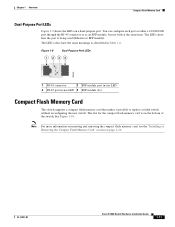
...on inserting and removing the compact flash memory card, see the "Installing or Removing the Compact Flash Memory Card" section on the bottom of the switch. You can configure each port as either a 10/100/1000 port through the RJ-45 connector or as described in -use LED 4 SFP ...flash memory card is being used (Ethernet or SFP module). OL-13017-01 Cisco IE 3000 Switch Hardware Installation Guide 1-11 The LED colors have the same meanings as an SFP module, but not both at the same time. Chapter 1 Overview Compact Flash Memory Card Dual-Purpose Port LEDs Figure 1-9 shows the LEDs on...
...on inserting and removing the compact flash memory card, see the "Installing or Removing the Compact Flash Memory Card" section on the bottom of the switch. You can configure each port as either a 10/100/1000 port through the RJ-45 connector or as described in -use LED 4 SFP ...flash memory card is being used (Ethernet or SFP module). OL-13017-01 Cisco IE 3000 Switch Hardware Installation Guide 1-11 The LED colors have the same meanings as an SFP module, but not both at the same time. Chapter 1 Overview Compact Flash Memory Card Dual-Purpose Port LEDs Figure 1-9 shows the LEDs on...
Installation Guide
Page 22
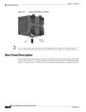
... Support. The feet stabilize the switch when it is mounted on either a DIN rail or a wall. See Figure 1-11. Rear-Panel Description Figure 1-10 Compact Flash Memory Card Slot Chapter 1 Overview 201832 Bottom 1 of the switch, modules, and power converter have latches for installation on the wall. 1-12 Cisco IE 3000 Switch Hardware Installation Guide OL-13017...
... Support. The feet stabilize the switch when it is mounted on either a DIN rail or a wall. See Figure 1-11. Rear-Panel Description Figure 1-10 Compact Flash Memory Card Slot Chapter 1 Overview 201832 Bottom 1 of the switch, modules, and power converter have latches for installation on the wall. 1-12 Cisco IE 3000 Switch Hardware Installation Guide OL-13017...
Installation Guide
Page 23
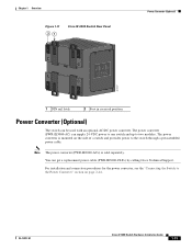
...) can get a replacement power cable (PWR-IE3000-CLP=) by calling Cisco Technical Support. OL-13017-01 Cisco IE 3000 Switch Hardware Installation Guide 1-13 Note The power converter (PWR-IE3000-AC=) is mounted on page 2-44. The power converter is sold separately. Chapter 1 Overview Figure 1-11 21 Cisco IE 3000 Switch Rear Panel Power Converter (Optional) 201697 1 DIN rail latch...
...) can get a replacement power cable (PWR-IE3000-CLP=) by calling Cisco Technical Support. OL-13017-01 Cisco IE 3000 Switch Hardware Installation Guide 1-13 Note The power converter (PWR-IE3000-AC=) is mounted on page 2-44. The power converter is sold separately. Chapter 1 Overview Figure 1-11 21 Cisco IE 3000 Switch Rear Panel Power Converter (Optional) 201697 1 DIN rail latch...
Installation Guide
Page 24
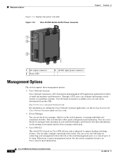
... web interface offers quick configuration and monitoring. For more information. 1-14 Cisco IE 3000 Switch Hardware Installation Guide OL-13017-01 You can configure and manage switch clusters or standalone switches. Management Options Figure 1-12 displays the power converter. Figure 1-12 Cisco IE 3000 Switch AC/DC Power Converter 1 2 3 Chapter 1 Overview 202314 1 DC output connector 2 Status LED 3 AC/DC input power...
... web interface offers quick configuration and monitoring. For more information. 1-14 Cisco IE 3000 Switch Hardware Installation Guide OL-13017-01 You can configure and manage switch clusters or standalone switches. Management Options Figure 1-12 displays the power converter. Figure 1-12 Cisco IE 3000 Switch AC/DC Power Converter 1 2 3 Chapter 1 Overview 202314 1 DC output connector 2 Status LED 3 AC/DC input power...
Installation Guide
Page 25
... objects are supported. The Cisco IE 3000 can be a standalone application or part of a Simple Network Management Protocol (SNMP) platform. OL-13017-01 Cisco IE 3000 Switch Hardware Installation Guide 1-15 ...The CiscoView application, which you can use to set of using the switch to create dedicated network segments and interconnecting the segments through Gigabit Ethernet connections. The switch supports a comprehensive set configuration parameters and to view the switch status and performance information. Chapter 1 Overview...
... objects are supported. The Cisco IE 3000 can be a standalone application or part of a Simple Network Management Protocol (SNMP) platform. OL-13017-01 Cisco IE 3000 Switch Hardware Installation Guide 1-15 ...The CiscoView application, which you can use to set of using the switch to create dedicated network segments and interconnecting the segments through Gigabit Ethernet connections. The switch supports a comprehensive set configuration parameters and to view the switch status and performance information. Chapter 1 Overview...

Installation Guide
Page 26
Network Configurations Chapter 1 Overview 1-16 Cisco IE 3000 Switch Hardware Installation Guide OL-13017-01
Network Configurations Chapter 1 Overview 1-16 Cisco IE 3000 Switch Hardware Installation Guide OL-13017-01
Installation Guide
Page 165
... to 2-53, B-49 to B-59 adapter pinouts, terminal RJ-45-to-DB-25 C-9 RJ-45-to-DB-9 C-8 adding modules to the switch B-8 airflow, required clearance 2-4, B-7 alarm relay connections connection procedures 2-33 to 2-35, B-38 to B-40 power and relay connector 1-6 altitude ... connectors and cables Cisco IOS command-line interface 1-14 Cisco IP Phones, connecting to 2-36, B-41 Cisco Network Assistant 1-14 CiscoView 1-15 clearance 2-4, B-7 CLI 1-14 command-line interface See CLI compact flash memory card installing, removing 2-10, B-13 overview 1-11 Cisco IE 3000 Switch Hardware Installation Guide IN...
... to 2-53, B-49 to B-59 adapter pinouts, terminal RJ-45-to-DB-25 C-9 RJ-45-to-DB-9 C-8 adding modules to the switch B-8 airflow, required clearance 2-4, B-7 alarm relay connections connection procedures 2-33 to 2-35, B-38 to B-40 power and relay connector 1-6 altitude ... connectors and cables Cisco IOS command-line interface 1-14 Cisco IP Phones, connecting to 2-36, B-41 Cisco Network Assistant 1-14 CiscoView 1-15 clearance 2-4, B-7 CLI 1-14 command-line interface See CLI compact flash memory card installing, removing 2-10, B-13 overview 1-11 Cisco IE 3000 Switch Hardware Installation Guide IN...

Software Configuration Guide
Page 3
...xxxi Conventions xxxi Related Publications xxxii Obtaining Documentation, Obtaining Support, and Security Guidelines xxxiii Overview 1-1 Features 1-1 Ease-of-Deployment and Ease-of-Use Features 1-2 Performance Features ...Switch 1-13 Ethernet-to-the-Factory Architecture 1-14 Enterprise Zone 1-15 Demilitarized Zone 1-15 Manufacturing Zone 1-15 Topology Options 1-17 Where to Go Next 1-20 Using the Command-Line Interface 2-1 Understanding Command Modes 2-1 Understanding the Help System 2-3 Understanding Abbreviated Commands 2-4 Understanding no and default Forms of Commands 2-4 Cisco IE 3000 Switch...
...xxxi Conventions xxxi Related Publications xxxii Obtaining Documentation, Obtaining Support, and Security Guidelines xxxiii Overview 1-1 Features 1-1 Ease-of-Deployment and Ease-of-Use Features 1-2 Performance Features ...Switch 1-13 Ethernet-to-the-Factory Architecture 1-14 Enterprise Zone 1-15 Demilitarized Zone 1-15 Manufacturing Zone 1-15 Topology Options 1-17 Where to Go Next 1-20 Using the Command-Line Interface 2-1 Understanding Command Modes 2-1 Understanding the Help System 2-3 Understanding Abbreviated Commands 2-4 Understanding no and default Forms of Commands 2-4 Cisco IE 3000 Switch...

Software Configuration Guide
Page 14
...-11 Extended-Range VLAN Configuration Guidelines 15-12 Creating an Extended-Range VLAN 15-12 Displaying VLANs 15-13 Configuring VLAN Trunks 15-14 Trunking Overview 15-14 IEEE 802.1Q Configuration Considerations 15-15 Default Layer 2 Ethernet Interface VLAN Configuration 15-16 Configuring an Ethernet Interface as a Trunk Port 15...-27 Changing the Retry Count 15-28 Monitoring the VMPS 15-28 Troubleshooting Dynamic-Access Port VLAN Membership 15-29 VMPS Configuration Example 15-29 Cisco IE 3000 Switch Software Configuration Guide xiv OL-13018-03
...-11 Extended-Range VLAN Configuration Guidelines 15-12 Creating an Extended-Range VLAN 15-12 Displaying VLANs 15-13 Configuring VLAN Trunks 15-14 Trunking Overview 15-14 IEEE 802.1Q Configuration Considerations 15-15 Default Layer 2 Ethernet Interface VLAN Configuration 15-16 Configuring an Ethernet Interface as a Trunk Port 15...-27 Changing the Retry Count 15-28 Monitoring the VMPS 15-28 Troubleshooting Dynamic-Access Port VLAN Membership 15-29 VMPS Configuration Example 15-29 Cisco IE 3000 Switch Software Configuration Guide xiv OL-13018-03

Software Configuration Guide
Page 16
Contents 19 C H A P T E R STP Overview 18-2 Spanning-Tree Topology and BPDUs 18-3 Bridge ID, Switch Priority, and Extended System ID 18-4 Spanning-Tree Interface States 18-4 Blocking State 18-5 Listening State 18-6 Learning State 18-6 Forwarding State 18-6 Disabled State 18-7 How a Switch or Port Becomes the Root Switch or Root Port 18-7 Spanning Tree and... Status 18-22 Configuring MSTP 19-1 Understanding MSTP 19-2 Multiple Spanning-Tree Regions 19-2 IST, CIST, and CST 19-2 Operations Within an MST Region 19-3 Cisco IE 3000 Switch Software Configuration Guide xvi OL-13018-03
Contents 19 C H A P T E R STP Overview 18-2 Spanning-Tree Topology and BPDUs 18-3 Bridge ID, Switch Priority, and Extended System ID 18-4 Spanning-Tree Interface States 18-4 Blocking State 18-5 Listening State 18-6 Learning State 18-6 Forwarding State 18-6 Disabled State 18-7 How a Switch or Port Becomes the Root Switch or Root Port 18-7 Spanning Tree and... Status 18-22 Configuring MSTP 19-1 Understanding MSTP 19-2 Multiple Spanning-Tree Regions 19-2 IST, CIST, and CST 19-2 Operations Within an MST Region 19-3 Cisco IE 3000 Switch Software Configuration Guide xvi OL-13018-03


