

Installation Guide
Page 3
... LED 1-9 Alarm LED 1-9 Power Status LED 1-9 10/100 Port Status LEDs 1-10 100Base-FX Port Status LEDs 1-10 Dual-Purpose Port LEDs 1-11 Compact Flash Memory Card 1-11 Rear-Panel Description 1-12 Power Converter (Optional) 1-13 Management Options 1-14 Network Configurations 1-15 Switch Installation 2-1 Preparing for Installation 2-1 Warnings 2-2 Cisco IE 3000 Switch Hardware Installation Guide...
... LED 1-9 Alarm LED 1-9 Power Status LED 1-9 10/100 Port Status LEDs 1-10 100Base-FX Port Status LEDs 1-10 Dual-Purpose Port LEDs 1-11 Compact Flash Memory Card 1-11 Rear-Panel Description 1-12 Power Converter (Optional) 1-13 Management Options 1-14 Network Configurations 1-15 Switch Installation 2-1 Preparing for Installation 2-1 Warnings 2-2 Cisco IE 3000 Switch Hardware Installation Guide...

Installation Guide
Page 4
... to 100BASE-FX Ports 2-43 Connecting the Switch to the Power Converter 2-44 Attaching the Power Converter to the Switch 2-45 Installing the Power Converter on a DIN Rail, Wall, or Rack Adapter 2-46 Connecting the DC Power Clip 2-46 Connecting the Power Converter to an AC Power Source 2-47 Cisco IE 3000 Switch Hardware Installation Guide iv OL-13017-01
... to 100BASE-FX Ports 2-43 Connecting the Switch to the Power Converter 2-44 Attaching the Power Converter to the Switch 2-45 Installing the Power Converter on a DIN Rail, Wall, or Rack Adapter 2-46 Connecting the DC Power Clip 2-46 Connecting the Power Converter to an AC Power Source 2-47 Cisco IE 3000 Switch Hardware Installation Guide iv OL-13017-01

Installation Guide
Page 5
...-13017-01 Preparing the AC Power Cord 2-47 Connecting the AC Power Cord to the Power Converter 2-48 Connecting the Power Converter to a DC Power Source 2-51 Applying Power to the Power Converter 2-53 Where to Go Next 2-53 Troubleshooting 3-1 Diagnosing Problems 3-1 Verify Switch POST Results 3-1 Verify Switch LEDs 3-2 Verify Switch Connections 3-2 Bad or Damaged Cable 3-2 Ethernet and Fiber Cables 3-2 Link...
...-13017-01 Preparing the AC Power Cord 2-47 Connecting the AC Power Cord to the Power Converter 2-48 Connecting the Power Converter to a DC Power Source 2-51 Applying Power to the Power Converter 2-53 Where to Go Next 2-53 Troubleshooting 3-1 Diagnosing Problems 3-1 Verify Switch POST Results 3-1 Verify Switch LEDs 3-2 Verify Switch Connections 3-2 Bad or Damaged Cable 3-2 Ethernet and Fiber Cables 3-2 Link...
Installation Guide
Page 6
... Rack Adapter B-52 Connecting the DC Power Clip B-52 Connecting the Power Converter to an AC Power Source B-53 Preparing the AC Power Cord B-53 Connecting the AC Power Cord to the Power Converter B-54 Connecting the Power Converter to a DC Power Source B-57 Applying Power to the Power Converter B-59 Cisco IE 3000 Switch Hardware Installation Guide vi OL-13017-01
... Rack Adapter B-52 Connecting the DC Power Clip B-52 Connecting the Power Converter to an AC Power Source B-53 Preparing the AC Power Cord B-53 Connecting the AC Power Cord to the Power Converter B-54 Connecting the Power Converter to a DC Power Source B-57 Applying Power to the Power Converter B-59 Cisco IE 3000 Switch Hardware Installation Guide vi OL-13017-01
Installation Guide
Page 11
...Description, page 1-12 • Power Converter (Optional), page 1-13 • Management Options, page 1-14 • Network Configurations, page 1-15 Overview The Cisco IE 3000 switch provides a rugged and secure switching infrastructure for industrial Ethernet applications, including factory automation, intelligent ...-01 Cisco IE 3000 Switch Hardware Installation Guide 1-1 It is suitable for harsh environments. This chapter provides a functional overview of the switches and covers these switches to office networking devices like Cisco IP Phones, Cisco Wireless Access Points ...
...Description, page 1-12 • Power Converter (Optional), page 1-13 • Management Options, page 1-14 • Network Configurations, page 1-15 Overview The Cisco IE 3000 switch provides a rugged and secure switching infrastructure for industrial Ethernet applications, including factory automation, intelligent ...-01 Cisco IE 3000 Switch Hardware Installation Guide 1-1 It is suitable for harsh environments. This chapter provides a functional overview of the switches and covers these switches to office networking devices like Cisco IP Phones, Cisco Wireless Access Points ...

Installation Guide
Page 12
... number of ports. Switch Models Chapter 1 Overview Switch Models Table 1-1 describes the switch and the expansion modules. Table 1-1 Cisco IE 3000 Switch Models Switch Model Cisco IE-3000-4TC Cisco IE-3000-8TC Cisco IEM-3000-8TM Cisco IEM-3000-8FM Description 4 10/100BASE-T Ethernet ports and 2 dual...; 100BASE-FX Ports, page 1-5 • Power and Relay Connector, page 1-5 • Console Port, page 1-6 • LEDs, page 1-6 The switch front panel contains the ports, the LEDs, and the power and relay connectors. Cisco IE 3000 Switch Hardware Installation Guide 1-2 OL-13017-01 For ...
... number of ports. Switch Models Chapter 1 Overview Switch Models Table 1-1 describes the switch and the expansion modules. Table 1-1 Cisco IE 3000 Switch Models Switch Model Cisco IE-3000-4TC Cisco IE-3000-8TC Cisco IEM-3000-8TM Cisco IEM-3000-8FM Description 4 10/100BASE-T Ethernet ports and 2 dual...; 100BASE-FX Ports, page 1-5 • Power and Relay Connector, page 1-5 • Console Port, page 1-6 • LEDs, page 1-6 The switch front panel contains the ports, the LEDs, and the power and relay connectors. Cisco IE 3000 Switch Hardware Installation Guide 1-2 OL-13017-01 For ...

Installation Guide
Page 13
Chapter 1 Overview Figure 1-1 Cisco IE-3000-8TC Switch 1 2 Front-Panel Description 201699 3 45 1 Power and relay connectors 4 10/100 ports 2 Console port 5 Protective ground connection 3 Dual-purpose ports Figure 1-2 Cisco IE-3000-4TC Switch 1 2 201700 3 45 1 Power and relay connectors 4 2 Console port 5 3 Dual-purpose ports 10/100 ports Protective ground connection OL-13017-01 Cisco IE 3000 Switch Hardware Installation Guide 1-3
Chapter 1 Overview Figure 1-1 Cisco IE-3000-8TC Switch 1 2 Front-Panel Description 201699 3 45 1 Power and relay connectors 4 10/100 ports 2 Console port 5 Protective ground connection 3 Dual-purpose ports Figure 1-2 Cisco IE-3000-4TC Switch 1 2 201700 3 45 1 Power and relay connectors 4 2 Console port 5 3 Dual-purpose ports 10/100 ports Protective ground connection OL-13017-01 Cisco IE 3000 Switch Hardware Installation Guide 1-3

Installation Guide
Page 15
...uplink interfaces when inserted in an SFP module slot. OL-13017-01 Cisco IE 3000 Switch Hardware Installation Guide 1-5 Only one port can use Gigabit Ethernet SFP modules to establish fiber-optic connections to other switches. You use a small-form-factor fixed (SFF) fiber-optic transceiver... module that accepts a dual LC connector. Power and Relay Connector You connect the DC power and alarm signals to workstations, servers, routers, and Cisco ...
...uplink interfaces when inserted in an SFP module slot. OL-13017-01 Cisco IE 3000 Switch Hardware Installation Guide 1-5 Only one port can use Gigabit Ethernet SFP modules to establish fiber-optic connections to other switches. You use a small-form-factor fixed (SFF) fiber-optic transceiver... module that accepts a dual LC connector. Power and Relay Connector You connect the DC power and alarm signals to workstations, servers, routers, and Cisco ...

Installation Guide
Page 16
..."Cable and Connectors." All LEDs are operational, the switch draws power from Cisco Systems. For console-port and adapter-pinout information, see the "Two Twisted-Pair Cable Pinouts" section on the power and relay connector are open , so under power failure conditions, the contacts are labeled A, and you...and the supplied RJ-45-to -DB-25 female DTE adapter. Cisco IE 3000 Switch Hardware Installation Guide 1-6 OL-13017-01 Front-Panel Description Chapter 1 Overview The switch accessory pack includes the mating power and relay connectors. Both alarm terminals on page C-5. You can ...
..."Cable and Connectors." All LEDs are operational, the switch draws power from Cisco Systems. For console-port and adapter-pinout information, see the "Two Twisted-Pair Cable Pinouts" section on the power and relay connector are open , so under power failure conditions, the contacts are labeled A, and you...and the supplied RJ-45-to -DB-25 female DTE adapter. Cisco IE 3000 Switch Hardware Installation Guide 1-6 OL-13017-01 Front-Panel Description Chapter 1 Overview The switch accessory pack includes the mating power and relay connectors. Both alarm terminals on page C-5. You can ...

Installation Guide
Page 19
... the alarm configuration. otherwise, the LED is operating normally. OL-13017-01 Cisco IE 3000 Switch Hardware Installation Guide 1-9 Table 1-4 Alarm Status LED Color System Status Off Alarms are not configured, or the switch is not present; Power Status LED The switch can operate with the higher voltage. If alarms are configured. If the one...
... the alarm configuration. otherwise, the LED is operating normally. OL-13017-01 Cisco IE 3000 Switch Hardware Installation Guide 1-9 Table 1-4 Alarm Status LED Color System Status Off Alarms are not configured, or the switch is not present; Power Status LED The switch can operate with the higher voltage. If alarms are configured. If the one...

Installation Guide
Page 20
... Link present. Activity. Port is disabled. 1-10 Cisco IE 3000 Switch Hardware Installation Guide OL-13017-01 See Table 1-7. The power status LEDs only show that power is sending or receiving data. The difference, or hysteresis, ensures that power is sending or receiving data. Table 1-6 displays LED...the individual ports. Front-Panel Description Chapter 1 Overview Note The Pwr A and Pwr B LEDs show that the power status LEDs do not oscillate at the switch input exceeds the valid level. Blinking amber A link blocked by Spanning Tree Protocol (STP) is present if ...
... Link present. Activity. Port is disabled. 1-10 Cisco IE 3000 Switch Hardware Installation Guide OL-13017-01 See Table 1-7. The power status LEDs only show that power is sending or receiving data. The difference, or hysteresis, ensures that power is sending or receiving data. Table 1-6 displays LED...the individual ports. Front-Panel Description Chapter 1 Overview Note The Pwr A and Pwr B LEDs show that the power status LEDs do not oscillate at the switch input exceeds the valid level. Blinking amber A link blocked by Spanning Tree Protocol (STP) is present if ...
Installation Guide
Page 22
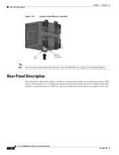
...obtain replacement flash memory cards (CF-IE3000=) by calling Cisco Technical Support. The latches slide outward to position the switch over a DIN rail and slide inward to secure the switch to a DIN rail. The feet stabilize the switch when it is mounted on either a DIN rail or ...a wall. Rear-Panel Description Figure 1-10 Compact Flash Memory Card Slot Chapter 1 Overview 201832 Bottom 1 of the switch, modules, and power converter have latches for installation on the wall. 1-12 Cisco IE 3000 Switch Hardware Installation...
...obtain replacement flash memory cards (CF-IE3000=) by calling Cisco Technical Support. The latches slide outward to position the switch over a DIN rail and slide inward to secure the switch to a DIN rail. The feet stabilize the switch when it is mounted on either a DIN rail or ...a wall. Rear-Panel Description Figure 1-10 Compact Flash Memory Card Slot Chapter 1 Overview 201832 Bottom 1 of the switch, modules, and power converter have latches for installation on the wall. 1-12 Cisco IE 3000 Switch Hardware Installation...
Installation Guide
Page 23
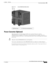
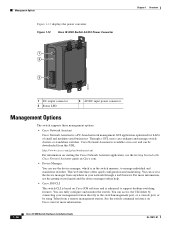
... connection procedures for the power converter, see the "Connecting the Switch to the Power Converter" section on the side of a switch and provides power to two modules. Chapter 1 Overview Figure 1-11 21 Cisco IE 3000 Switch Rear Panel Power Converter (Optional) 201697 1 DIN rail latch 2 Foot in recessed position Power Converter (Optional) The switch can get a replacement power cable (PWR-IE3000...
... connection procedures for the power converter, see the "Connecting the Switch to the Power Converter" section on the side of a switch and provides power to two modules. Chapter 1 Overview Figure 1-11 21 Cisco IE 3000 Switch Rear Panel Power Converter (Optional) 201697 1 DIN rail latch 2 Foot in recessed position Power Converter (Optional) The switch can get a replacement power cable (PWR-IE3000...
Installation Guide
Page 24
... switch. You can access the device manager from this URL: http://www.cisco.com/go/networkassistant For information on starting the Cisco Network Assistant application, see the getting started guide and the device manager online help. • Cisco IOS CLI The switch CLI is enhanced to manage individual and standalone switches. Management Options Figure 1-12 displays the power...
... switch. You can access the device manager from this URL: http://www.cisco.com/go/networkassistant For information on starting the Cisco Network Assistant application, see the getting started guide and the device manager online help. • Cisco IOS CLI The switch CLI is enhanced to manage individual and standalone switches. Management Options Figure 1-12 displays the power...
Installation Guide
Page 27
... page 2-3 • Verifying Package Contents, page 2-5 OL-13017-01 Cisco IE 3000 Switch Hardware Installation Guide 2-1 Caution If your switch, interpret the power-on self-test (POST), and connect the switch to Go Next, page 2-53 Preparing for Installation This section provides information ...Installation, page 2-1 • Adding Modules to the Switch, page 2-5 • Installing or Removing the Compact Flash Memory Card, page 2-10 • Verifying Switch Operation, page 2-11 • Installing the Switch, page 2-23 • Connecting Power and Alarm Circuits, page 2-32 • Connecting ...
... page 2-3 • Verifying Package Contents, page 2-5 OL-13017-01 Cisco IE 3000 Switch Hardware Installation Guide 2-1 Caution If your switch, interpret the power-on self-test (POST), and connect the switch to Go Next, page 2-53 Preparing for Installation This section provides information ...Installation, page 2-1 • Adding Modules to the Switch, page 2-5 • Installing or Removing the Compact Flash Memory Card, page 2-10 • Verifying Switch Operation, page 2-11 • Installing the Switch, page 2-23 • Connecting Power and Alarm Circuits, page 2-32 • Connecting ...
Installation Guide
Page 28
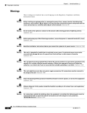
... heat up when connected to power and ground and can be accessed only through an approved network termination unit with integral circuit protection. 10/100/1000 Ethernet Statement 1044 Cisco IE 3000 Switch Hardware Installation Guide 2-2 OL-13017-01 Statement 1030 Warning Ultimate disposal of this equipment. Preparing for Installation Chapter 2 Switch Installation Warnings These warnings...
... heat up when connected to power and ground and can be accessed only through an approved network termination unit with integral circuit protection. 10/100/1000 Ethernet Statement 1044 Cisco IE 3000 Switch Hardware Installation Guide 2-2 OL-13017-01 Statement 1030 Warning Ultimate disposal of this equipment. Preparing for Installation Chapter 2 Switch Installation Warnings These warnings...
Installation Guide
Page 30
...-FX fiber-optic ports, the cable length from a switch to a Class 2 DC power source. Front-panel LEDs can result in the "Verifying Switch Operation" section on and running POST. Access to assure proper grounding. When determining where to place the switch, observe these conditions: - Cisco IE 3000 Switch Hardware Installation Guide 2-4 OL-13017-01 Follow the procedures...
...-FX fiber-optic ports, the cable length from a switch to a Class 2 DC power source. Front-panel LEDs can result in the "Verifying Switch Operation" section on and running POST. Access to assure proper grounding. When determining where to place the switch, observe these conditions: - Cisco IE 3000 Switch Hardware Installation Guide 2-4 OL-13017-01 Follow the procedures...
Installation Guide
Page 31
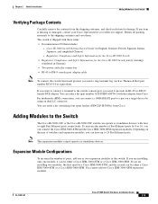
Cisco IE 3000 Switch Getting Started Guide (in German) • Two power and relay connectors • RJ-45 to DB-9 console port adapter cable Note To connect the switch functional ground, you can have up to 24 Fast Ethernet ports. For multimode (MM) connections, you need ... Module Configurations To increase the number of Fast Ethernet ports by using an dual-LC connector. The switch is missing or damaged, contact your Cisco representative or reseller for support. Chapter 2 Switch Installation Adding Modules to the Switch Verifying Package Contents Carefully remove the contents from...
Cisco IE 3000 Switch Getting Started Guide (in German) • Two power and relay connectors • RJ-45 to DB-9 console port adapter cable Note To connect the switch functional ground, you can have up to 24 Fast Ethernet ports. For multimode (MM) connections, you need ... Module Configurations To increase the number of Fast Ethernet ports by using an dual-LC connector. The switch is missing or damaged, contact your Cisco representative or reseller for support. Chapter 2 Switch Installation Adding Modules to the Switch Verifying Package Contents Carefully remove the contents from...
Installation Guide
Page 37
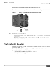
... switch passes the power-on the bottom of switch Step 2 Install or remove the card, as desired: • To remove the card, grasp the card top, and pull it firmly in place. Chapter 2 Switch Installation Verifying Switch Operation Follow these directions to the Console Port, page 2-12 • Verifying Switch Operation, page 2-11 OL-13017-01 Cisco...
... switch passes the power-on the bottom of switch Step 2 Install or remove the card, as desired: • To remove the card, grasp the card top, and pull it firmly in place. Chapter 2 Switch Installation Verifying Switch Operation Follow these directions to the Console Port, page 2-12 • Verifying Switch Operation, page 2-11 OL-13017-01 Cisco...
Installation Guide
Page 39
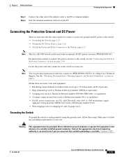
For instructions on how to connect the power converter to the switch, see the "Connecting the Switch to earth ground by calling Cisco Technical Support. and 18-gauge wires Grounding the Switch To ground the switch to the Power Converter" section on page x. Note You can be grounded. See the "Obtaining...Never defeat the ground conductor or operate the equipment in the absence of the adapter cable to the Switch, page 2-21 Note The Cisco IE 3000 switch can get replacement power and relay connectors (PWR-IE3000-CNCT=) by using the ground screw, follow any grounding requirements at ...
For instructions on how to connect the power converter to the switch, see the "Connecting the Switch to earth ground by calling Cisco Technical Support. and 18-gauge wires Grounding the Switch To ground the switch to the Power Converter" section on page x. Note You can be grounded. See the "Obtaining...Never defeat the ground conductor or operate the equipment in the absence of the adapter cable to the Switch, page 2-21 Note The Cisco IE 3000 switch can get replacement power and relay connectors (PWR-IE3000-CNCT=) by using the ground screw, follow any grounding requirements at ...
