

Hardware Installation Guide
Page 1
Cisco ME 4924-10GE Ethernet Switch Hardware Installation Guide September 2006 Americas Headquarters Cisco Systems, Inc. 170 West Tasman Drive San Jose, CA 95134-1706 USA http://www.cisco.com Tel: 408 526-4000 800 553-NETS (6387) Fax: 408 527-0883 Text Part Number: OL-10071-01
Cisco ME 4924-10GE Ethernet Switch Hardware Installation Guide September 2006 Americas Headquarters Cisco Systems, Inc. 170 West Tasman Drive San Jose, CA 95134-1706 USA http://www.cisco.com Tel: 408 526-4000 800 553-NETS (6387) Fax: 408 527-0883 Text Part Number: OL-10071-01

Hardware Installation Guide
Page 2
... reasonable protection against harmful interference in a commercial environment. Third-party trademarks mentioned are designed to part 15 of the FCC rules. Cisco ME 4924-10GE Ethernet Switch Hardware Installation Guide © 2006-2012 Cisco Systems, Inc. The following information is operated in a residential installation. The following measures: • Reorient or relocate the receiving antenna...
... reasonable protection against harmful interference in a commercial environment. Third-party trademarks mentioned are designed to part 15 of the FCC rules. Cisco ME 4924-10GE Ethernet Switch Hardware Installation Guide © 2006-2012 Cisco Systems, Inc. The following information is operated in a residential installation. The following measures: • Reorient or relocate the receiving antenna...

Hardware Installation Guide
Page 3
... Statement 1071-Warning Definition viii Related Publications xiv Obtaining Documentation xiv Cisco.com xiv Product Documentation DVD xv Ordering Documentation xv Documentation Feedback xv Cisco Product Security Overview xv Reporting Security Problems in Cisco Products xvi Product Alerts and Field Notices xvi Obtaining Technical Assistance...Software Features 1-2 Optical Support 1-3 Front Panel Description 1-3 Console Port 1-3 Management Port 1-4 SFP Module Ports 1-4 LEDs 1-4 Rear Panel Description 1-6 Power Supplies 1-7 CONTENTS Cisco ME 4924-10GE Ethernet Switch Hardware Installation Guide iii
... Statement 1071-Warning Definition viii Related Publications xiv Obtaining Documentation xiv Cisco.com xiv Product Documentation DVD xv Ordering Documentation xv Documentation Feedback xv Cisco Product Security Overview xv Reporting Security Problems in Cisco Products xvi Product Alerts and Field Notices xvi Obtaining Technical Assistance...Software Features 1-2 Optical Support 1-3 Front Panel Description 1-3 Console Port 1-3 Management Port 1-4 SFP Module Ports 1-4 LEDs 1-4 Rear Panel Description 1-6 Power Supplies 1-7 CONTENTS Cisco ME 4924-10GE Ethernet Switch Hardware Installation Guide iii
Hardware Installation Guide
Page 4
... C H A P T E R 3 C H A P T E R Environmental Monitoring of the Power Supplies 1-7 Power Management for the Cisco ME 4924-10GE Switch 1-7 Power Management Modes 1-8 Management Options 1-8 Network Configurations 1-8 Switch Installation 2-1 Preparing for Installation 2-1 Warnings 2-1 Installation Guidelines 2-3 Verifying Package ... to Go Next 2-18 Connecting the Power Supply 3-1 Grounding Requirements 3-1 Connecting AC Power to the Cisco ME 4924-10GE Switch 3-2 Connecting DC Power to the Cisco ME 4924-10GE Switch 3-3 Cisco ME 4924-10GE Ethernet Switch Hardware Installation Guide iv OL-10071-01
... C H A P T E R 3 C H A P T E R Environmental Monitoring of the Power Supplies 1-7 Power Management for the Cisco ME 4924-10GE Switch 1-7 Power Management Modes 1-8 Management Options 1-8 Network Configurations 1-8 Switch Installation 2-1 Preparing for Installation 2-1 Warnings 2-1 Installation Guidelines 2-3 Verifying Package ... to Go Next 2-18 Connecting the Power Supply 3-1 Grounding Requirements 3-1 Connecting AC Power to the Cisco ME 4924-10GE Switch 3-2 Connecting DC Power to the Cisco ME 4924-10GE Switch 3-3 Cisco ME 4924-10GE Ethernet Switch Hardware Installation Guide iv OL-10071-01
Hardware Installation Guide
Page 5
... Switch C-1 Starting the Terminal-Emulation Software C-2 Connecting to a Power Source C-3 Entering the Initial Configuration Information C-4 IP Settings C-4 Performing the Initial Configuration C-4 Contents OL-10071-01 Cisco ME 4924-10GE Ethernet Switch Hardware Installation Guide v
... Switch C-1 Starting the Terminal-Emulation Software C-2 Connecting to a Power Source C-3 Entering the Initial Configuration Information C-4 IP Settings C-4 Performing the Initial Configuration C-4 Contents OL-10071-01 Cisco ME 4924-10GE Ethernet Switch Hardware Installation Guide v
Hardware Installation Guide
Page 6
Contents Cisco ME 4924-10GE Ethernet Switch Hardware Installation Guide vi OL-10071-01
Contents Cisco ME 4924-10GE Ethernet Switch Hardware Installation Guide vi OL-10071-01

Hardware Installation Guide
Page 7
... networking or computer technician responsible for the switches and the regulatory agency approvals. OL-10071-01 Cisco ME 4924-10GE Ethernet Switch Hardware Installation Guide vii On the Cisco Product Documentation home page, select Release 12.2 from the Cisco.com home page at Service and Support > Technical Documents. Chapter 4, "Troubleshooting," describes how to identify and...
... networking or computer technician responsible for the switches and the regulatory agency approvals. OL-10071-01 Cisco ME 4924-10GE Ethernet Switch Hardware Installation Guide vii On the Cisco Product Documentation home page, select Release 12.2 from the Cisco.com home page at Service and Support > Technical Documents. Chapter 4, "Troubleshooting," describes how to identify and...

Hardware Installation Guide
Page 8
... procedure for notes, cautions, and warnings: Note Means reader take note. Caution Means reader be used to connect to the switch. BEWAAR DEZE INSTRUCTIES Cisco ME 4924-10GE Ethernet Switch Hardware Installation Guide viii OL-10071-01 SAVE THESE INSTRUCTIONS Waarschuwing BELANGRIJKE VEILIGHEIDSINSTRUCTIES Dit waarschuwingssymbool betekent gevaar. Conventions This document uses these conventions...
... procedure for notes, cautions, and warnings: Note Means reader take note. Caution Means reader be used to connect to the switch. BEWAAR DEZE INSTRUCTIES Cisco ME 4924-10GE Ethernet Switch Hardware Installation Guide viii OL-10071-01 SAVE THESE INSTRUCTIONS Waarschuwing BELANGRIJKE VEILIGHEIDSINSTRUCTIES Dit waarschuwingssymbool betekent gevaar. Conventions This document uses these conventions...
Hardware Installation Guide
Page 12
Conventions Preface Cisco ME 4924-10GE Ethernet Switch Hardware Installation Guide xii OL-10071-01
Conventions Preface Cisco ME 4924-10GE Ethernet Switch Hardware Installation Guide xii OL-10071-01
Hardware Installation Guide
Page 13
Preface Conventions OL-10071-01 Cisco ME 4924-10GE Ethernet Switch Hardware Installation Guide xiii
Preface Conventions OL-10071-01 Cisco ME 4924-10GE Ethernet Switch Hardware Installation Guide xiii
Hardware Installation Guide
Page 14
... documentation, at Catalyst 4500 users. • Release Notes for the Cisco ME 4924-10GE Switch (not orderable, but available on Cisco.com) • Cisco ME 4924-10GE Ethernet Switch Getting Started Guide (order number DOC-7817609=) • Regulatory Compliance and Safety Information for the Cisco ME 4924 Ethernet Switch (order number DOC-7817610=) • Catalyst 4500 Series Switch Software...
... documentation, at Catalyst 4500 users. • Release Notes for the Cisco ME 4924-10GE Switch (not orderable, but available on Cisco.com) • Cisco ME 4924-10GE Ethernet Switch Getting Started Guide (order number DOC-7817609=) • Regulatory Compliance and Safety Information for the Cisco ME 4924 Ethernet Switch (order number DOC-7817610=) • Catalyst 4500 Series Switch Software...
Hardware Installation Guide
Page 15
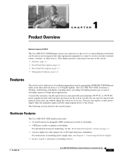
...provide fault-tolerance protection for high-speed applications. Product Overview 1 C H A P T E R Revised: January 12, 2012 The Cisco ME 4924-10GE Ethernet switch, also referred to as the switch, is a metro Ethernet switch that support AC or DC input and power redundancy For ...supply units, see Chapter 3, "Connecting the Power Supply." • Layer 2, Layer 3, and Layer 4 switching services OL-10071-01 Cisco ME 4924-10GE Ethernet Switch Hardware Installation Guide 1-1 The following sections describe the switch features. This chapter provides a functional overview of the switch: •...
...provide fault-tolerance protection for high-speed applications. Product Overview 1 C H A P T E R Revised: January 12, 2012 The Cisco ME 4924-10GE Ethernet switch, also referred to as the switch, is a metro Ethernet switch that support AC or DC input and power redundancy For ...supply units, see Chapter 3, "Connecting the Power Supply." • Layer 2, Layer 3, and Layer 4 switching services OL-10071-01 Cisco ME 4924-10GE Ethernet Switch Hardware Installation Guide 1-1 The following sections describe the switch features. This chapter provides a functional overview of the switch: •...
Hardware Installation Guide
Page 16
... • Storm control in -band management through any switch port through a terminal attached to the console interface - Embedded CiscoView support Cisco ME 4924-10GE Ethernet Switch Hardware Installation Guide 1-2 OL-10071-01 IEEE 802.1Q VLAN tagging on a per -second actual forwarding rate • ... Port Aggregation Protocol (PAgP) for Gigabit EtherChannel • Catalyst 4500 series management software features include the following : - The Cisco ME 4924-10GE software provides: • Support for 55,000 MAC addresses for Layer 2 switching • Support for 4,096 VLANs and 4,096 VLAN ...
... • Storm control in -band management through any switch port through a terminal attached to the console interface - Embedded CiscoView support Cisco ME 4924-10GE Ethernet Switch Hardware Installation Guide 1-2 OL-10071-01 IEEE 802.1Q VLAN tagging on a per -second actual forwarding rate • ... Port Aggregation Protocol (PAgP) for Gigabit EtherChannel • Catalyst 4500 series management software features include the following : - The Cisco ME 4924-10GE software provides: • Support for 55,000 MAC addresses for Layer 2 switching • Support for 4,096 VLANs and 4,096 VLAN ...
Hardware Installation Guide
Page 17
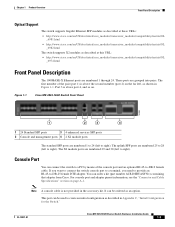
...on page A-1. The first member of the console port and an optional RJ-45-to right). Figure 1-1 Cisco ME 4924-10GE Switch Front Panel 13 14 15 16 17 18 19 20 21 22 23 24 Cisco ME 4924-10GE 154869 1 2 3 4 1 24 Standard SFP ports 3 4 enhanced services SFP ports 2 Console and... console port and adapter pinout information, see the "Connector and Cable Specifications" section on the far left to right). OL-10071-01 Cisco ME 4924-10GE Ethernet Switch Hardware Installation Guide 1-3 Port 3 is not provided in Appendix C, "Initial Configuration for the Switch." It can connect the switch...
...on page A-1. The first member of the console port and an optional RJ-45-to right). Figure 1-1 Cisco ME 4924-10GE Switch Front Panel 13 14 15 16 17 18 19 20 21 22 23 24 Cisco ME 4924-10GE 154869 1 2 3 4 1 24 Standard SFP ports 3 4 enhanced services SFP ports 2 Console and... console port and adapter pinout information, see the "Connector and Cable Specifications" section on the far left to right). OL-10071-01 Cisco ME 4924-10GE Ethernet Switch Hardware Installation Guide 1-3 Port 3 is not provided in Appendix C, "Initial Configuration for the Switch." It can connect the switch...
Hardware Installation Guide
Page 18
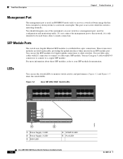
...use the SFP modules for configuration and monitoring traffic. LEDs You can use the switch LEDs to this network, it is operating normally. Figure 1-2 Cisco ME 4924-10GE Switch LEDs PS1 PS2 FAN STATUS 1 2 3 4 5 6 7 8 9 10 11 12 13 14 15 16 17 18 19 20... 24 PS1 PS2 FAN STATUS 4 1 2 3 1 2 3 4 5 6 5 7 8 1 Power Supply 1 LED 2 Power Supply 2 LED 3 FAN LED 4 STATUS LED 5 Port LED Cisco ME 4924-10GE Ethernet Switch Hardware Installation Guide 1-4 154870 OL-10071-01 This port is not active while the switch is only intended to a copper SFP module.
...use the SFP modules for configuration and monitoring traffic. LEDs You can use the switch LEDs to this network, it is operating normally. Figure 1-2 Cisco ME 4924-10GE Switch LEDs PS1 PS2 FAN STATUS 1 2 3 4 5 6 7 8 9 10 11 12 13 14 15 16 17 18 19 20... 24 PS1 PS2 FAN STATUS 4 1 2 3 1 2 3 4 5 6 5 7 8 1 Power Supply 1 LED 2 Power Supply 2 LED 3 FAN LED 4 STATUS LED 5 Port LED Cisco ME 4924-10GE Ethernet Switch Hardware Installation Guide 1-4 154870 OL-10071-01 This port is not active while the switch is only intended to a copper SFP module.
Hardware Installation Guide
Page 19
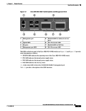
...ports 6 X2-1 Port status LED 7 Enabled LED for X2 Ports 8 X2-2 Port status LED The LEDs on the front panel of the Cisco ME 4924-10GE switch (see Figure 1-2 and Figure 1-3) provide status information as follows: • STATUS LED indicates the operating state of the LED functions.... Table 1-1 provides a description of the Cisco ME 4924-10GE switch. • PS1 LED indicates the internal power supply status. • PS2 LED indicates the internal power supply status. • FAN ...
...ports 6 X2-1 Port status LED 7 Enabled LED for X2 Ports 8 X2-2 Port status LED The LEDs on the front panel of the Cisco ME 4924-10GE switch (see Figure 1-2 and Figure 1-3) provide status information as follows: • STATUS LED indicates the operating state of the LED functions.... Table 1-1 provides a description of the Cisco ME 4924-10GE switch. • PS1 LED indicates the internal power supply status. • PS2 LED indicates the internal power supply status. • FAN ...
Hardware Installation Guide
Page 20
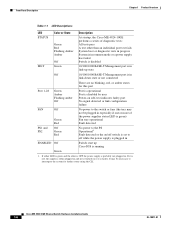
Cisco ME 4924-10GE Ethernet Switch Hardware Installation Guide 1-6 OL-10071-01 It may not be necessary to off while the power supply is ...Description Chapter 1 Product Overview Table 1-1 LED Descriptions LED Color or State Description STATUS Green Red Flashing Amber Amber Off At startup, the Cisco ME 4924-10GE performs a series of the power supplies status LED is green) Fan tray operational Fault detected PS1 and PS2 Off Green Red No power... failure FAN Off Green Red No power to the switch or fans (the tray may be plugged in link-up Cisco IOS is running Green 1.
Cisco ME 4924-10GE Ethernet Switch Hardware Installation Guide 1-6 OL-10071-01 It may not be necessary to off while the power supply is ...Description Chapter 1 Product Overview Table 1-1 LED Descriptions LED Color or State Description STATUS Green Red Flashing Amber Amber Off At startup, the Cisco ME 4924-10GE performs a series of the power supplies status LED is green) Fan tray operational Fault detected PS1 and PS2 Off Green Red No power... failure FAN Off Green Red No power to the switch or fans (the tray may be plugged in link-up Cisco IOS is running Green 1.

Hardware Installation Guide
Page 21
.... A power cord is necessary to the site AC power source. Note For environmental specifications, see Appendix A, "Technical Specifications." The Cisco 4924-10GE switch has two redundant internal 300 W AC or 300 W DC power supplies. The internal power supplies have individual power cords and ... Rear Panel Description The switch rear panel has two power bays anda field replaceable fan tray. (See Figure 1-4.) Figure 1-4 Cisco ME 4924-10GE Switch Rear Panel 1 2 3 Cisco ME 4924-10GE 154872 CON MGMT 25 26 ENABLED 27 28 29 ENABLED 30 4 5 6 7 8 1 Power supply PS1 on/off ...
.... A power cord is necessary to the site AC power source. Note For environmental specifications, see Appendix A, "Technical Specifications." The Cisco 4924-10GE switch has two redundant internal 300 W AC or 300 W DC power supplies. The internal power supplies have individual power cords and ... Rear Panel Description The switch rear panel has two power bays anda field replaceable fan tray. (See Figure 1-4.) Figure 1-4 Cisco ME 4924-10GE Switch Rear Panel 1 2 3 Cisco ME 4924-10GE 154872 CON MGMT 25 26 ENABLED 27 28 29 ENABLED 30 4 5 6 7 8 1 Power supply PS1 on/off ...
Hardware Installation Guide
Page 22
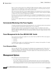
...requirements at all times. AC and DC supplies are operating normally, each provides from a remote management station. Power Management Modes The Cisco ME 4924-10GE switch supports the redundant power management mode. To create a partial configuration that you must use a power supply cord or have ... diagnosed by resolving adverse environmental conditions prior to cover the empty power bay. DC supplies should have an on the AC Cisco ME 4924-10GE switch power supplies; If conditions reach critical thresholds, the power supply might shut down to 100 percent of operation. If...
...requirements at all times. AC and DC supplies are operating normally, each provides from a remote management station. Power Management Modes The Cisco ME 4924-10GE switch supports the redundant power management mode. To create a partial configuration that you must use a power supply cord or have ... diagnosed by resolving adverse environmental conditions prior to cover the empty power bay. DC supplies should have an on the AC Cisco ME 4924-10GE switch power supplies; If conditions reach critical thresholds, the power supply might shut down to 100 percent of operation. If...

Hardware Installation Guide
Page 45
...power command indicate a power or other means of security. Connecting DC Power to the Cisco ME 4924-10GE Switch Follow these steps and warnings when connecting DC power to the Cisco 4924-10GE switch: Warning Before performing any of the building installation. Statement 1017 Warning This product ... Step 1 Step 2 Step 3 Prior to connecting the power supply to be provided as described in service. OL-10071-01 Cisco ME 4924-10GE Ethernet Switch Hardware Installation Guide 3-3 Statement 1045 Warning Hazardous voltage or energy may be accessed only through the use of a special...
...power command indicate a power or other means of security. Connecting DC Power to the Cisco ME 4924-10GE Switch Follow these steps and warnings when connecting DC power to the Cisco 4924-10GE switch: Warning Before performing any of the building installation. Statement 1017 Warning This product ... Step 1 Step 2 Step 3 Prior to connecting the power supply to be provided as described in service. OL-10071-01 Cisco ME 4924-10GE Ethernet Switch Hardware Installation Guide 3-3 Statement 1045 Warning Hazardous voltage or energy may be accessed only through the use of a special...


