

Hardware Installation Guide
Page 3
...Statement 1071-Warning Definition viii Related Publications xiv Obtaining Documentation xiv Cisco.com xiv Product Documentation DVD xv Ordering Documentation xv Documentation Feedback xv Cisco Product Security Overview xv Reporting Security Problems in Cisco Products xvi Product Alerts and Field Notices xvi Obtaining Technical ... 1-1 Software Features 1-2 Optical Support 1-3 Front Panel Description 1-3 Console Port 1-3 Management Port 1-4 SFP Module Ports 1-4 LEDs 1-4 Rear Panel Description 1-6 Power Supplies 1-7 CONTENTS Cisco ME 4924-10GE Ethernet Switch Hardware Installation Guide iii
...Statement 1071-Warning Definition viii Related Publications xiv Obtaining Documentation xiv Cisco.com xiv Product Documentation DVD xv Ordering Documentation xv Documentation Feedback xv Cisco Product Security Overview xv Reporting Security Problems in Cisco Products xvi Product Alerts and Field Notices xvi Obtaining Technical ... 1-1 Software Features 1-2 Optical Support 1-3 Front Panel Description 1-3 Console Port 1-3 Management Port 1-4 SFP Module Ports 1-4 LEDs 1-4 Rear Panel Description 1-6 Power Supplies 1-7 CONTENTS Cisco ME 4924-10GE Ethernet Switch Hardware Installation Guide iii
Hardware Installation Guide
Page 4
... Removing the 10-Gigabit Ethernet X2 Module 2-16 Module Maintenance Guidelines 2-16 Cleaning the Fiber-Optic Connectors 2-17 Where to Go Next 2-18 Connecting the Power Supply 3-1 Grounding Requirements 3-1 Connecting AC Power to the Cisco ME 4924-10GE Switch 3-2 Connecting DC Power to the Cisco ME 4924-10GE Switch 3-3 Cisco ME 4924-10GE Ethernet Switch Hardware Installation Guide iv OL-10071-01
... Removing the 10-Gigabit Ethernet X2 Module 2-16 Module Maintenance Guidelines 2-16 Cleaning the Fiber-Optic Connectors 2-17 Where to Go Next 2-18 Connecting the Power Supply 3-1 Grounding Requirements 3-1 Connecting AC Power to the Cisco ME 4924-10GE Switch 3-2 Connecting DC Power to the Cisco ME 4924-10GE Switch 3-3 Cisco ME 4924-10GE Ethernet Switch Hardware Installation Guide iv OL-10071-01
Hardware Installation Guide
Page 5
... 4-3 Getting Started 4-4 Problem Solving to the System Component Level 4-4 Identifying Startup Problems 4-4 LED Readings 4-5 Troubleshooting the Power Supply 4-6 Contacting Customer Service 4-6 Technical Specifications A-1 Connector and Cable Specifications B-1 Connector Specifications B-1 Connecting to 1000BASE-T Devices B-1...the Terminal-Emulation Software C-2 Connecting to a Power Source C-3 Entering the Initial Configuration Information C-4 IP Settings C-4 Performing the Initial Configuration C-4 Contents OL-10071-01 Cisco ME 4924-10GE Ethernet Switch Hardware Installation Guide v
... 4-3 Getting Started 4-4 Problem Solving to the System Component Level 4-4 Identifying Startup Problems 4-4 LED Readings 4-5 Troubleshooting the Power Supply 4-6 Contacting Customer Service 4-6 Technical Specifications A-1 Connector and Cable Specifications B-1 Connector Specifications B-1 Connecting to 1000BASE-T Devices B-1...the Terminal-Emulation Software C-2 Connecting to a Power Source C-3 Entering the Initial Configuration Information C-4 IP Settings C-4 Performing the Initial Configuration C-4 Contents OL-10071-01 Cisco ME 4924-10GE Ethernet Switch Hardware Installation Guide v

Hardware Installation Guide
Page 7
... the switch in a rack, on a wall, on the Cisco.com Product Documentation home page. Chapter 3, "Connecting the Power Supply," describes how to connect the AC and DC power supply units and how to identify and resolve some of the problems ...Cisco.com home page at Service and Support > Technical Documents. Chapter 2, "Switch Installation," has the procedures on how to power the switch, how to make port connections. Appendix A, "Technical Specifications," lists the physical and environmental specifications for installing the Cisco ME 4924-10GE Ethernet switch. OL-10071-01 Cisco ME 4924-10GE...
... the switch in a rack, on a wall, on the Cisco.com Product Documentation home page. Chapter 3, "Connecting the Power Supply," describes how to connect the AC and DC power supply units and how to identify and resolve some of the problems ...Cisco.com home page at Service and Support > Technical Documents. Chapter 2, "Switch Installation," has the procedures on how to power the switch, how to make port connections. Appendix A, "Technical Specifications," lists the physical and environmental specifications for installing the Cisco ME 4924-10GE Ethernet switch. OL-10071-01 Cisco ME 4924-10GE...
Hardware Installation Guide
Page 15
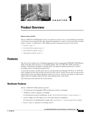
...service. A faulty fan tray may also replace a faulty power supply while the redundant supply provides uninterrupted power to the switch. The following sections describe the switch features. Hardware Features The Cisco ME 4924-10GE hardware provides: • 24 small form-factor pluggable (SFP...numbering, see the "Front Panel Description" section on installing power supply units, see Chapter 3, "Connecting the Power Supply." • Layer 2, Layer 3, and Layer 4 switching services OL-10071-01 Cisco ME 4924-10GE Ethernet Switch Hardware Installation Guide 1-1 A removable automatic variable...
...service. A faulty fan tray may also replace a faulty power supply while the redundant supply provides uninterrupted power to the switch. The following sections describe the switch features. Hardware Features The Cisco ME 4924-10GE hardware provides: • 24 small form-factor pluggable (SFP...numbering, see the "Front Panel Description" section on installing power supply units, see Chapter 3, "Connecting the Power Supply." • Layer 2, Layer 3, and Layer 4 switching services OL-10071-01 Cisco ME 4924-10GE Ethernet Switch Hardware Installation Guide 1-1 A removable automatic variable...
Hardware Installation Guide
Page 18
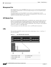
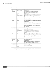
... STATUS 1 2 3 4 5 6 7 8 9 10 11 12 13 14 15 16 17 18 19 20 21 22 23 24 PS1 PS2 FAN STATUS 4 1 2 3 1 2 3 4 5 6 5 7 8 1 Power Supply 1 LED 2 Power Supply 2 LED 3 FAN LED 4 STATUS LED 5 Port LED Cisco ME 4924-10GE Ethernet Switch Hardware Installation Guide 1-4 154870 OL-10071-01 D o not connect the management port to this network, it is used (in...
... STATUS 1 2 3 4 5 6 7 8 9 10 11 12 13 14 15 16 17 18 19 20 21 22 23 24 PS1 PS2 FAN STATUS 4 1 2 3 1 2 3 4 5 6 5 7 8 1 Power Supply 1 LED 2 Power Supply 2 LED 3 FAN LED 4 STATUS LED 5 Port LED Cisco ME 4924-10GE Ethernet Switch Hardware Installation Guide 1-4 154870 OL-10071-01 D o not connect the management port to this network, it is used (in...
Hardware Installation Guide
Page 19
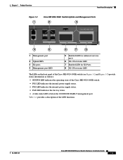
... Switch Hardware Installation Guide 1-5 Chapter 1 Product Overview Front Panel Description Figure 1-3 1 Cisco ME 4924-10GE Switch Uplinks and Management Ports 2 3 Cisco ME 4924-10GE 154872 CON MGMT 25 26 ENABLED 27 28 29 ENABLED 30 4 5 6 7 8 1 Management port 2 Uplink SFPs 3...indicates the operating state of the LED functions. Table 1-1 provides a description of the Cisco ME 4924-10GE switch. • PS1 LED indicates the internal power supply status. • PS2 LED indicates the internal power supply status. • FAN LED indicates the fan tray status. • A link ...
... Switch Hardware Installation Guide 1-5 Chapter 1 Product Overview Front Panel Description Figure 1-3 1 Cisco ME 4924-10GE Switch Uplinks and Management Ports 2 3 Cisco ME 4924-10GE 154872 CON MGMT 25 26 ENABLED 27 28 29 ENABLED 30 4 5 6 7 8 1 Management port 2 Uplink SFPs 3...indicates the operating state of the LED functions. Table 1-1 provides a description of the Cisco ME 4924-10GE switch. • PS1 LED indicates the internal power supply status. • PS2 LED indicates the internal power supply status. • FAN LED indicates the fan tray status. • A link ...
Hardware Installation Guide
Page 20
... Color or State Description STATUS Green Red Flashing Amber Amber Off At startup, the Cisco ME 4924-10GE performs a series of the power supplies status LED is green) Fan tray operational Fault detected PS1 and PS2 Off Green Red No power to the PS Operational1 Fault detected or the on or it is running Green 1. ... switch or fans (the tray may be plugged in and not switched on /off while the power supply is plugged in ENABLED Off Switch start up Cisco IOS is faulty. If it is red, the supply is either LED is green and the other than an individual port test fails System boot or...
... Color or State Description STATUS Green Red Flashing Amber Amber Off At startup, the Cisco ME 4924-10GE performs a series of the power supplies status LED is green) Fan tray operational Fault detected PS1 and PS2 Off Green Red No power to the PS Operational1 Fault detected or the on or it is running Green 1. ... switch or fans (the tray may be plugged in and not switched on /off while the power supply is plugged in ENABLED Off Switch start up Cisco IOS is faulty. If it is red, the supply is either LED is green and the other than an individual port test fails System boot or...

Hardware Installation Guide
Page 21
... chassis components. Note For environmental specifications, see Appendix A, "Technical Specifications." The Cisco 4924-10GE switch has two redundant internal 300 W AC or 300 W DC power supplies. The system should not be left operating without a fan tray for the Cisco ME 4924-10GE switch, see Appendix A, "Technical Specifications." A power cord is drawn in from the sides of the chassis. The...
... chassis components. Note For environmental specifications, see Appendix A, "Technical Specifications." The Cisco 4924-10GE switch has two redundant internal 300 W AC or 300 W DC power supplies. The system should not be left operating without a fan tray for the Cisco ME 4924-10GE switch, see Appendix A, "Technical Specifications." A power cord is drawn in from the sides of the chassis. The...
Hardware Installation Guide
Page 22
... the AC Cisco ME 4924-10GE switch power supplies; Each power supply monitors its input status. Power Management for the Cisco ME 4924-10GE Switch You can maintain normal system operation by resolving adverse environmental conditions prior to loss of the Power Supplies Using the environmental monitoring and reporting functions, you always connect both power supplies are interchangeable. For safety reasons, the AC power supply needs to...
... the AC Cisco ME 4924-10GE switch power supplies; Each power supply monitors its input status. Power Management for the Cisco ME 4924-10GE Switch You can maintain normal system operation by resolving adverse environmental conditions prior to loss of the Power Supplies Using the environmental monitoring and reporting functions, you always connect both power supplies are interchangeable. For safety reasons, the AC power supply needs to...

Hardware Installation Guide
Page 27
...regulatory statements, see the Regulatory Compliance and Safety Information for Installation Warning This unit might have more than one power supply connection. Refer to intrabuilding or unexposed wiring or cabling. Statement 1040 Warning When installing or replacing the unit,...parts inside. Statement 1028 Warning Only trained and qualified personnel should be removed to your Cisco representative or reseller for damage. OL-10071-01 Cisco ME 4924-10GE Ethernet Switch Hardware Installation Guide 2-3 Installation Guidelines Installation instructions and cabling distances vary from...
...regulatory statements, see the Regulatory Compliance and Safety Information for Installation Warning This unit might have more than one power supply connection. Refer to intrabuilding or unexposed wiring or cabling. Statement 1040 Warning When installing or replacing the unit,...parts inside. Statement 1028 Warning Only trained and qualified personnel should be removed to your Cisco representative or reseller for damage. OL-10071-01 Cisco ME 4924-10GE Ethernet Switch Hardware Installation Guide 2-3 Installation Guidelines Installation instructions and cabling distances vary from...
Hardware Installation Guide
Page 28
...=) containing that the switch passes POST. Follow these items: • Cisco ME 4924-10GE Ethernet Switch Getting Started Guide • Regulatory Compliance and Safety Information for the Cisco ME 4924-10GE Ethernet Switch • AC power supply (installed) or a DC power supply (installed with ground lug installed) • AC power cord (AC-powered switches) • One fan tray • One grounding lug...
...=) containing that the switch passes POST. Follow these items: • Cisco ME 4924-10GE Ethernet Switch Getting Started Guide • Regulatory Compliance and Safety Information for the Cisco ME 4924-10GE Ethernet Switch • AC power supply (installed) or a DC power supply (installed with ground lug installed) • AC power cord (AC-powered switches) • One fan tray • One grounding lug...
Hardware Installation Guide
Page 29
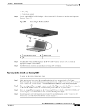
..., or attach an appropriate adapter to the terminal. Secure the power cord with the power cord retainer. OL-10071-01 Cisco ME 4924-10GE Ethernet Switch Hardware Installation Guide 2-5 Start the terminal-emulation program if you are using a DC power supply, see the "Connecting AC Power to the Cisco ME 4924-10GE Switch" section on connecting to the switch console port...
..., or attach an appropriate adapter to the terminal. Secure the power cord with the power cord retainer. OL-10071-01 Cisco ME 4924-10GE Ethernet Switch Hardware Installation Guide 2-5 Start the terminal-emulation program if you are using a DC power supply, see the "Connecting AC Power to the Cisco ME 4924-10GE Switch" section on connecting to the switch console port...
Hardware Installation Guide
Page 43
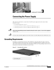
...; Grounding Requirements, page 3-1 • Connecting AC Power to the Cisco ME 4924-10GE Switch, page 3-2 • Connecting DC Power to the Cisco ME 4924-10GE Switch, page 3-3 Warning Only trained and qualified personnel should be used. Grounding Requirements Grounding is recommended on the right side of the chassis, and either one power supply in your switch, always cover the other...
...; Grounding Requirements, page 3-1 • Connecting AC Power to the Cisco ME 4924-10GE Switch, page 3-2 • Connecting DC Power to the Cisco ME 4924-10GE Switch, page 3-3 Warning Only trained and qualified personnel should be used. Grounding Requirements Grounding is recommended on the right side of the chassis, and either one power supply in your switch, always cover the other...
Hardware Installation Guide
Page 44
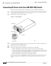
.... Connecting AC Power to the Cisco ME 4924-10GE Switch Chapter 3 Connecting the Power Supply Connecting AC Power to the Cisco ME 4924-10GE Switch Follow these steps and warnings when connecting power to the Cisco ME 4924-10GE switch: Step 1 Step 2 Prior to connecting the power supply to the switch. Plug the power cords into the power supplies. For more information on different circuits. Cisco ME 4924-10GE Ethernet Switch Hardware...
.... Connecting AC Power to the Cisco ME 4924-10GE Switch Chapter 3 Connecting the Power Supply Connecting AC Power to the Cisco ME 4924-10GE Switch Follow these steps and warnings when connecting power to the Cisco ME 4924-10GE switch: Step 1 Step 2 Prior to connecting the power supply to the switch. Plug the power cords into the power supplies. For more information on different circuits. Cisco ME 4924-10GE Ethernet Switch Hardware...

Hardware Installation Guide
Page 45
... Step 1 Step 2 Step 3 Prior to connecting the power supply to a power source, ensure that power is intended for troubleshooting information. Connect the power supply ground terminal to the Cisco ME 4924-10GE Switch If the LEDs or show power command indicate a power or other means of the building installation. Chapter 3 Connecting the Power Supply Connecting DC Power to earth ground. Statement 1045 Warning Hazardous...
... Step 1 Step 2 Step 3 Prior to connecting the power supply to a power source, ensure that power is intended for troubleshooting information. Connect the power supply ground terminal to the Cisco ME 4924-10GE Switch If the LEDs or show power command indicate a power or other means of the building installation. Chapter 3 Connecting the Power Supply Connecting DC Power to earth ground. Statement 1045 Warning Hazardous...
Hardware Installation Guide
Page 46
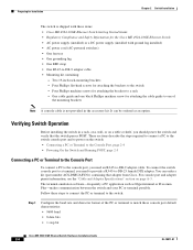
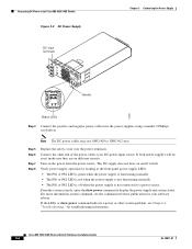
.... For more information on /off when the power supply is off switch. Note The DC power cables may use AWG #10 to the Cisco ME 4924-10GE Switch Figure 3-3 DC Power Supply DC input terminals Chapter 3 Connecting the Power Supply Handle 120697 Status LEDs Step 4 Connect the positive and negative power cables into the power supplies using a number 2 Phillips screwdriver. Turn on different...
.... For more information on /off when the power supply is off switch. Note The DC power cables may use AWG #10 to the Cisco ME 4924-10GE Switch Figure 3-3 DC Power Supply DC input terminals Chapter 3 Connecting the Power Supply Handle 120697 Status LEDs Step 4 Connect the positive and negative power cables into the power supplies using a number 2 Phillips screwdriver. Turn on different...
Hardware Installation Guide
Page 47
... the switch LEDs, see the "LEDs" section on self-test (POST), port-connectivity problems, and overall switch performance. If one of the power supplies is complete and the switch has passed, the STATUS LED turns green. The switch may not be red. Refer to ensure that the switch ...page 4-1 • Diagnosing Problems, page 4-2 • Troubleshooting the Hardware Components, page 4-3 • Contacting Customer Service, page 4-6 Understanding POST Results When the switch powers on page 1-4. OL-10071-01 Cisco ME 4924-10GE Ethernet Switch Hardware Installation Guide 4-1
... the switch LEDs, see the "LEDs" section on self-test (POST), port-connectivity problems, and overall switch performance. If one of the power supplies is complete and the switch has passed, the STATUS LED turns green. The switch may not be red. Refer to ensure that the switch ...page 4-1 • Diagnosing Problems, page 4-2 • Troubleshooting the Hardware Components, page 4-3 • Contacting Customer Service, page 4-6 Understanding POST Results When the switch powers on page 1-4. OL-10071-01 Cisco ME 4924-10GE Ethernet Switch Hardware Installation Guide 4-1
Hardware Installation Guide
Page 49
...Cisco-approved SFP. The SFP module might be a fatal error. The SFP module does not snap into the port. Inspect for information on the management console Amber STATUS LED The switch port is placed in this chapter to the System Component Level, page 4-4 • Identifying Startup Problems, page 4-4 • Troubleshooting the Power Supply... to 9600 baud. OL-10071-01 Cisco ME 4924-10GE Ethernet Switch Hardware Installation Guide 4-3 Troubleshooting the Hardware Components This chapter describes how to troubleshoot the Cisco ME 4924-10GE-10GE switch hardware and contains these sections: ...
...Cisco-approved SFP. The SFP module might be a fatal error. The SFP module does not snap into the port. Inspect for information on the management console Amber STATUS LED The switch port is placed in this chapter to the System Component Level, page 4-4 • Identifying Startup Problems, page 4-4 • Troubleshooting the Power Supply... to 9600 baud. OL-10071-01 Cisco ME 4924-10GE Ethernet Switch Hardware Installation Guide 4-3 Troubleshooting the Hardware Components This chapter describes how to troubleshoot the Cisco ME 4924-10GE-10GE switch hardware and contains these sections: ...
Hardware Installation Guide
Page 50
... to the Cisco ME 4924-10GE, follow these steps: Step 1 Step 2 Step 3 Step 4 Flip the power switches to the on position (AC powered systems only ). Troubleshooting the Hardware Components Chapter 4 Troubleshooting Getting Started When the initial system boot is complete, verify the following subsystems: • Power supply-Includes the power supply and power supply cooling. (See the "Troubleshooting the Power Supply" section on...
... to the Cisco ME 4924-10GE, follow these steps: Step 1 Step 2 Step 3 Step 4 Flip the power switches to the on position (AC powered systems only ). Troubleshooting the Hardware Components Chapter 4 Troubleshooting Getting Started When the initial system boot is complete, verify the following subsystems: • Power supply-Includes the power supply and power supply cooling. (See the "Troubleshooting the Power Supply" section on...


