Cisco PWR 800 WW1 - HW ROUTERS L/M Support and Manuals
Get Help and Manuals for this Cisco item

View All Support Options Below
Free Cisco PWR 800 WW1 manuals!
Problems with Cisco PWR 800 WW1?
Ask a Question
Free Cisco PWR 800 WW1 manuals!
Problems with Cisco PWR 800 WW1?
Ask a Question
Popular Cisco PWR 800 WW1 Manual Pages
Hardware Installation Guide - Page 1

Cisco 800 Series Routers Hardware Installation Guide
Corporate Headquarters Cisco Systems, Inc. 170 West Tasman Drive San Jose, CA 95134-1706 USA http://www.cisco.com Tel: 408 526-4000
800 553-NETS (6387) Fax: 408 526-4100
Customer Order Number: DOC-785373= Text Part Number: 78-5373-04
Hardware Installation Guide - Page 6
... PC 2-17 Connecting the Power Supply 2-18
Mounting Your Router 2-18 Mounting on a Table 2-18 Mounting on a Wall 2-19
Verifying Installation 2-20 Where to Go from Here 2-22
Troubleshooting 3-1 Problems During First Startup 3-2 Problems After First Startup 3-3 Problems After Router Is Running 3-5 When Contacting Your Cisco Reseller 3-7
ISDN and IDSL Concepts A-1
Specifications and Cables B-1 System...
Hardware Installation Guide - Page 18
... Ethernet network device.
Cisco 800 Series Routers Hardware Installation Guide
1-4
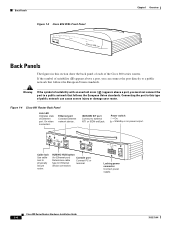
78-5373-04 Figure 1-4 Cisco 801 Router Back Panel...Power switch l = On.
= Standby or no power output.
11666
LINK
HUB NO HUB
ETHERNET
10 BASE T
Cisco 801
CONSOLE
ISDN S/T
Cable lock Use cable lock to external NT1 or ISDN wall jack. device connection.
Locking power connector Connect power supply...
Hardware Installation Guide - Page 19
....
11668
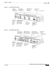
Cable lock Use cable lock to physically secure router.
PHONE
1 2
Locking power connector Connect power supply.
78-5373-04
Cisco 800 Series Routers Hardware Installation Guide
1-5 ISDN BRI S/T port Connect to ISDN wall jack. Power switch l = On.
= Standby or no power output. Console port Connect PC or terminal. ISDN BRI U port Connect to external NT1 or ISDN wall jack...
Hardware Installation Guide - Page 20
... output.
11669
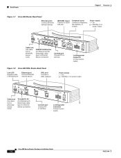
Cable lock Use cable lock to physically secure router. Locking power connector Connect power supply.
30771
Cisco 800 Series Routers Hardware Installation Guide
1-6
78-5373-04
Power switch l = On.
= Standby or no power output. Telephone ports Connect to IDSL wall jack.
Figure 1-8 Cisco 802 IDSL Router Back Panel
Link LED Indicates state of Ethernet port.
HUB NO HUB...
Hardware Installation Guide - Page 21
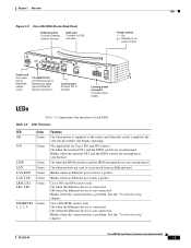
... only.
Blinks when the connection has a problem.
Blinks when an Ethernet port receives a packet. Off when the Ethernet device is connected. See the "Troubleshooting" chapter.
78-5373-04
Cisco 800 Series Routers Hardware Installation Guide
1-7 IDSL port Connect to physically secure router. Locking power connector Connect power supply.
Cisco 804 IDSL routers only.
On when the...
Hardware Installation Guide - Page 26
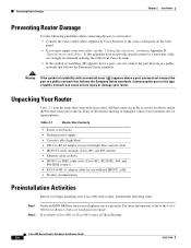
... information, refer to your customer service representative. If any of public network can connect the port directly to a public network that follows the European Union standards. Warning
If the symbol of suitability ( ) appears above a port, you have a Cisco 801 or Cisco 803 router, do the following:
Cisco 800 Series Routers Hardware Installation Guide
2-4
78-5373-04 If this...
Hardware Installation Guide - Page 40
...8226; Table or other horizontal surface • Wall or other end of the following guidelines:
2-18
Cisco 800 Series Routers Hardware Installation Guide
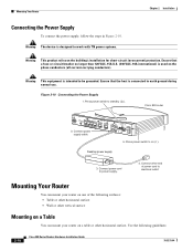
78-5373-04 Figure 2-10 Connecting the Power Supply 1. Connect power supply cable. Press power switch to power supply.
4.
Warning The device is used on ( ). Connect other vertical surface
Mounting on a Table
You can mount...
Hardware Installation Guide - Page 41
...
Cisco 800 Series Routers Hardware Installation Guide
2-19 If the screws are located on the bottom of router
11671
When mounting the router, the following conditions must be easily visible.
• The back panel must provide the screws. The last page of the network cable connections could pull the router from the connector on the power supply...
Hardware Installation Guide - Page 42
...
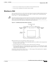
cm)
Screw
Maximum distance 6 ft (18 m)
11672
Chapter 2 Installation
Front panel
Mounting brackets 2. If the LEDs are not on horizontal surface. The LINK LED is on Wall
1.
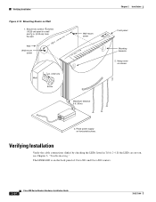
Verifying Installation
Figure 2-12 Mounting Router on the back panel of Cisco 801 and Cisco 802 routers.
2-20
Cisco 800 Series Routers Hardware Installation Guide
78-5373-04 Hang router on screws.
3.
Hardware Installation Guide - Page 46
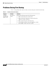
...Problem
No power to and from the power
supply are off. Cisco 800 Series Routers Hardware Installation Guide
3-2
78-5373-04 Solutions Perform the following steps in the following order: • Make sure that the power switch is ON. • Make sure that could occur after you turn on the power switch for the first time.
Problems During First Startup
Chapter 3 Troubleshooting
Problems...
Hardware Installation Guide - Page 55
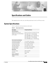
... for the Cisco 800 series routers. Table B-1 System Specifications
Description Physical Dimensions Dimensions (H x W x D) Weight (does not include desktop power supply)
Environmental Operating Ranges Nonoperating temperature Nonoperating humidity Nonoperating altitude Operating temperature Operating humidity Operating altitude Router Power AC input voltage Frequency Power consumption Telephone...
Hardware Installation Guide - Page 67
..., hazard vii
D
damage electrostatic discharge (ESD) 2-3 router, preventing 2-4
D channel A-1 digital telephone 2-14 DRAM, adding 1-2
E
electrostatic discharge (ESD), preventing 2-3 Ethernet
cable specifications B-7 cable types 2-6 devices, connecting 2-6 port described 1-2 port illustrated 1-4 to 1-7 European Union standards 2-4
Cisco 800 Series Routers Hardware Installation Guide
IN-1
Hardware Installation Guide - Page 68
...L
LEDs
IN-2
Cisco 800 Series Routers Hardware Installation Guide
described 1-7 illustrated 1-3 to 1-6 locking power connector, illustrated 1-4 to 1-7
M
modem, connecting 2-15 mounting the router 2-18
N
network device button settings 2-6 to 2-7 NT1 feature 1-2
P
panels, illustrated 1-4 to 1-7 PC, connecting 2-9, 2-17 port connector pinouts B-2 to B-6 ports for specific routers 1-3 power
problems...
Hardware Installation Guide - Page 69
...
connecting 2-14, 2-15 ports
described 1-2 illustrated 1-5, 1-6 temperature specifications B-1 terminal, connecting 2-17 TO HUB/TO PC button illustrated 1-6 to 1-7 settings 2-6 to 2-20 warnings, installation 2-2 weight specifications B-1 workstation, connecting 2-9
U
U interface A-1 United Kingdom master sockets 2-16
78-5373-04
Cisco 800 Series Routers Hardware Installation Guide
IN-3
Cisco PWR 800 WW1 Reviews
We have not received any reviews for Cisco yet.