
Hardware Installation Guide
Page 6
...Digital Telephone 2-14 Connecting an Analog Telephone, Fax, or Modem 2-15 Connecting a Terminal or PC 2-17 Connecting the Power Supply 2-18 Mounting Your Router 2-18 Mounting on a Table 2-18 Mounting on a Wall 2-19 Verifying Installation 2-20 Where to Go from Here 2-...22 Troubleshooting 3-1 Problems During First Startup 3-2 Problems After First Startup 3-3 Problems After Router Is Running 3-5 When Contacting Your Cisco Reseller 3-7 ISDN and IDSL Concepts A-1 Specifications and Cables B-1 System Specifications B-1 Port Connector Pinouts B-2 Cabling Specifications B-6 ...
...Digital Telephone 2-14 Connecting an Analog Telephone, Fax, or Modem 2-15 Connecting a Terminal or PC 2-17 Connecting the Power Supply 2-18 Mounting Your Router 2-18 Mounting on a Table 2-18 Mounting on a Wall 2-19 Verifying Installation 2-20 Where to Go from Here 2-...22 Troubleshooting 3-1 Problems During First Startup 3-2 Problems After First Startup 3-3 Problems After Router Is Running 3-5 When Contacting Your Cisco Reseller 3-7 ISDN and IDSL Concepts A-1 Specifications and Cables B-1 System Specifications B-1 Port Connector Pinouts B-2 Cabling Specifications B-6 ...
Hardware Installation Guide
Page 18
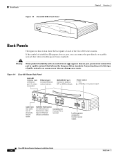
... Connecting the port to this section show the back panel of each of the Cisco 800 series routers. On when connected. Back Panels Figure 1-3 Cisco 804 IDSL Front Panel IDSL ETHERNET IDSL Chapter 1 Overview 30770 Back Panels The ...figures in this type of public network can connect the port directly to a public network that follows the European Union standards. Figure 1-4 Cisco 801 Router Back Panel Link LED Indicates state of Ethernet port. Locking power connector Connect power supply...
... Connecting the port to this section show the back panel of each of the Cisco 800 series routers. On when connected. Back Panels Figure 1-3 Cisco 804 IDSL Front Panel IDSL ETHERNET IDSL Chapter 1 Overview 30770 Back Panels The ...figures in this type of public network can connect the port directly to a public network that follows the European Union standards. Figure 1-4 Cisco 801 Router Back Panel Link LED Indicates state of Ethernet port. Locking power connector Connect power supply...
Hardware Installation Guide
Page 19
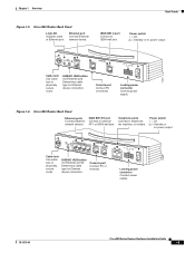
.... 11668 Cable lock Use cable lock to physically secure router. Console port Connect PC or terminal. PHONE 1 2 Locking power connector Connect power supply. 78-5373-04 Cisco 800 Series Routers Hardware Installation Guide 1-5 Ethernet port Connect Ethernet network device. Locking power connector Connect power supply. 11667 Figure 1-6 Cisco 803 Router Back Panel Ethernet ports Connect Ethernet network devices. ISDN BRI S/T port Connect...
.... 11668 Cable lock Use cable lock to physically secure router. Console port Connect PC or terminal. PHONE 1 2 Locking power connector Connect power supply. 78-5373-04 Cisco 800 Series Routers Hardware Installation Guide 1-5 Ethernet port Connect Ethernet network device. Locking power connector Connect power supply. 11667 Figure 1-6 Cisco 803 Router Back Panel Ethernet ports Connect Ethernet network devices. ISDN BRI S/T port Connect...
Hardware Installation Guide
Page 20
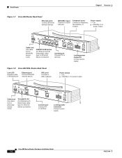
... Connect to telephone, fax machine, or modem. Power switch l = On. = Standby or no power output. Cisco 804 CONSOLE ISDN U Console port Connect PC or terminal. Power switch l = On. = Standby or no power output. 11669 Cable lock Use cable lock to physically secure router. Locking power connector Connect power supply. 30771 Cisco 800 Series Routers Hardware Installation Guide 1-6 78-5373-04 Back Panels...
... Connect to telephone, fax machine, or modem. Power switch l = On. = Standby or no power output. Cisco 804 CONSOLE ISDN U Console port Connect PC or terminal. Power switch l = On. = Standby or no power output. 11669 Cable lock Use cable lock to physically secure router. Locking power connector Connect power supply. 30771 Cisco 800 Series Routers Hardware Installation Guide 1-6 78-5373-04 Back Panels...
Hardware Installation Guide
Page 21
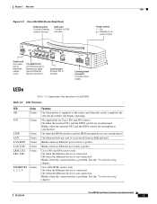
... Use cable lock to IDSL wall jack. IDSL port Connect to physically secure router. Locking power connector Connect power supply. LEDs Table 1-3 summarizes the function of each LED. Blinks when an Ethernet port receives a packet. Off when the Ethernet device is not connected. See the "Troubleshooting" chapter. 78-5373-04 Cisco 800 Series Routers Hardware Installation Guide 1-7
... Use cable lock to IDSL wall jack. IDSL port Connect to physically secure router. Locking power connector Connect power supply. LEDs Table 1-3 summarizes the function of each LED. Blinks when an Ethernet port receives a packet. Off when the Ethernet device is not connected. See the "Troubleshooting" chapter. 78-5373-04 Cisco 800 Series Routers Hardware Installation Guide 1-7
Hardware Installation Guide
Page 26
... network that come with your router. Table 2-1 Router Box Contents • Power cord (black) • Desktop power supply • Console cable (light blue) • DB-9-to-RJ-45 adapter for use with red ISDN U cable • Product documentation Preinstallation Activities Before you have a Cisco 801 or Cisco 803 router, do the following: Cisco 800 Series Routers Hardware Installation Guide 2-4 78-5373...
... network that come with your router. Table 2-1 Router Box Contents • Power cord (black) • Desktop power supply • Console cable (light blue) • DB-9-to-RJ-45 adapter for use with red ISDN U cable • Product documentation Preinstallation Activities Before you have a Cisco 801 or Cisco 803 router, do the following: Cisco 800 Series Routers Hardware Installation Guide 2-4 78-5373...
Hardware Installation Guide
Page 32
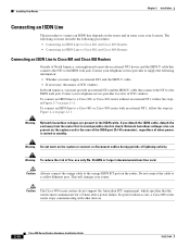
Contact your telephone service provider to supply the following procedures: • Connecting an ISDN Line to Cisco 801 and Cisco 803 Routers • Connecting an ISDN Line to Cisco 802 and Cisco 804 Routers Connecting an ISDN Line to Cisco 801 and Cisco 803 Routers Outside of fire, use only No.... ISDN cable, detach the end away from the router first to a yellow Ethernet port. If you must communicate for a list of lightning activity. Warning Do not work on the router. If a power failure occurs, a Cisco 800 series router stops communicating with an external NT1, follow the steps...
Contact your telephone service provider to supply the following procedures: • Connecting an ISDN Line to Cisco 801 and Cisco 803 Routers • Connecting an ISDN Line to Cisco 802 and Cisco 804 Routers Connecting an ISDN Line to Cisco 801 and Cisco 803 Routers Outside of fire, use only No.... ISDN cable, detach the end away from the router first to a yellow Ethernet port. If you must communicate for a list of lightning activity. Warning Do not work on the router. If a power failure occurs, a Cisco 800 series router stops communicating with an external NT1, follow the steps...
Hardware Installation Guide
Page 40
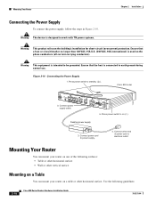
... a table or other horizontal surface. Desktop power supply 3. Ensure that the host is intended to power supply. 4. Warning This equipment is connected to electrical outlet. Cisco 803 CONSOLE ISDN S/T PHONE 1 2 5. Connect power cord to be grounded. Mounting Your Router You can mount your router on one of the following guidelines: 2-18 Cisco 800 Series Routers Hardware Installation Guide 78-5373-04...
... a table or other horizontal surface. Desktop power supply 3. Ensure that the host is intended to power supply. 4. Warning This equipment is connected to electrical outlet. Cisco 803 CONSOLE ISDN S/T PHONE 1 2 5. Connect power cord to be grounded. Mounting Your Router You can mount your router on one of the following guidelines: 2-18 Cisco 800 Series Routers Hardware Installation Guide 78-5373-04...
Hardware Installation Guide
Page 41
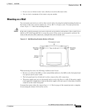
... drill bit) to secure the screws. If the screws are located on the router sides. • You can mount your router is not supported, it might place strain on the power supply cable and cause it to disconnect from the wall. You must provide the screws...power supply must rest on a horizontal surface such as the floor or a table. Figure 2-11 Wall-Mounting Brackets (Bottom of Router) Front panel of router Mounting bracket 7 5 8 in. (19.35 cm) Mounting bracket Bottom of this manual provides a template for measuring the distance between the screws. 78-5373-04 Cisco 800 Series Routers...
... drill bit) to secure the screws. If the screws are located on the router sides. • You can mount your router is not supported, it might place strain on the power supply cable and cause it to disconnect from the wall. You must provide the screws...power supply must rest on a horizontal surface such as the floor or a table. Figure 2-11 Wall-Mounting Brackets (Bottom of Router) Front panel of router Mounting bracket 7 5 8 in. (19.35 cm) Mounting bracket Bottom of this manual provides a template for measuring the distance between the screws. 78-5373-04 Cisco 800 Series Routers...
Hardware Installation Guide
Page 42
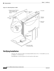
Verifying Installation Figure 2-12 Mounting Router on the back panel of Cisco 801 and Cisco 802 routers. 2-20 Cisco 800 Series Routers Hardware Installation Guide 78-5373-04 The LINK LED is on Wall 1. Place power supply on , see Chapter 3, "Troubleshooting." If the LEDs are not on horizontal surface. Secure two screws 7 5 8 inches (19.35 cm) apart in a wall and... the cable connections (links) by checking the LEDs listed in . (0.32 cm) Screw Maximum distance 6 ft (18 m) 11672 Chapter 2 Installation Front panel Mounting brackets 2. Hang router on screws. 3.
Verifying Installation Figure 2-12 Mounting Router on the back panel of Cisco 801 and Cisco 802 routers. 2-20 Cisco 800 Series Routers Hardware Installation Guide 78-5373-04 The LINK LED is on Wall 1. Place power supply on , see Chapter 3, "Troubleshooting." If the LEDs are not on horizontal surface. Secure two screws 7 5 8 inches (19.35 cm) apart in a wall and... the cable connections (links) by checking the LEDs listed in . (0.32 cm) Screw Maximum distance 6 ft (18 m) 11672 Chapter 2 Installation Front panel Mounting brackets 2. Hang router on screws. 3.
Hardware Installation Guide
Page 46
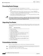
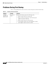
... the following steps in the following order: • Make sure that the power switch is ON. • Make sure that all connections to router. Cisco 800 Series Routers Hardware Installation Guide 3-2 78-5373-04 Contact your Cisco reseller. Problem No power to and from the power supply are off. Problems During First Startup Chapter 3 Troubleshooting Problems During First Startup...
... the following steps in the following order: • Make sure that the power switch is ON. • Make sure that all connections to router. Cisco 800 Series Routers Hardware Installation Guide 3-2 78-5373-04 Contact your Cisco reseller. Problem No power to and from the power supply are off. Problems During First Startup Chapter 3 Troubleshooting Problems During First Startup...

Hardware Installation Guide
Page 47
.... • Improperly set router HUB/NO HUB or TO...supply your own cable, make sure you have a Cisco 801 or 803 router in North America or in parts of Europe, you might need to connect the router... to an external NT1 and connect the NT1 to an ISDN wall jack. • If outside of North America, contact your Cisco... (On Cisco 801, Cisco 802, and 802 IDSL routers, the LINK...Cisco 800 Series Routers Hardware Installation Guide 3-3 Improperly connected cable. - Connect NT1 as described in the "Connecting an ISDN Line to Cisco 801 and Cisco 803 Routers...jack. On Cisco 803 and 804 routers, the LK...
.... • Improperly set router HUB/NO HUB or TO...supply your own cable, make sure you have a Cisco 801 or 803 router in North America or in parts of Europe, you might need to connect the router... to an external NT1 and connect the NT1 to an ISDN wall jack. • If outside of North America, contact your Cisco... (On Cisco 801, Cisco 802, and 802 IDSL routers, the LINK...Cisco 800 Series Routers Hardware Installation Guide 3-3 Improperly connected cable. - Connect NT1 as described in the "Connecting an ISDN Line to Cisco 801 and Cisco 803 Routers...jack. On Cisco 803 and 804 routers, the LK...
Hardware Installation Guide
Page 55
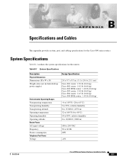
... power supply) Environmental Operating Ranges Nonoperating temperature Nonoperating humidity Nonoperating altitude Operating temperature Operating humidity Operating altitude Router Power AC input voltage Frequency Power consumption Telephone Port Power Voltage Design Specification 2.0 x 9.7 x 8.3 in. (5.1 x 24.6 x 21.1 cm) Cisco 801 router: 1.39 lb (0.63 kg) Cisco 802 router: 1.42 lb (0.64 kg) Cisco 802 IDSL router: 1.42 lb (0.64 kg) Cisco 803 router: 1.44 lb (0.65 kg) Cisco...
... power supply) Environmental Operating Ranges Nonoperating temperature Nonoperating humidity Nonoperating altitude Operating temperature Operating humidity Operating altitude Router Power AC input voltage Frequency Power consumption Telephone Port Power Voltage Design Specification 2.0 x 9.7 x 8.3 in. (5.1 x 24.6 x 21.1 cm) Cisco 801 router: 1.39 lb (0.63 kg) Cisco 802 router: 1.42 lb (0.64 kg) Cisco 802 IDSL router: 1.42 lb (0.64 kg) Cisco 803 router: 1.44 lb (0.65 kg) Cisco...
Hardware Installation Guide
Page 67
... power supply 2-18 server 2-9 telephones 2-14, 2-15 terminal or PC 2-17 workstation 2-9 console port description 1-2 illustrated 1-4 to 1-7 conventions, hazard vii D damage electrostatic discharge (ESD) 2-3 router, preventing 2-4 D channel A-1 digital telephone 2-14 DRAM, adding 1-2 E electrostatic discharge (ESD), preventing 2-3 Ethernet cable specifications B-7 cable types 2-6 devices, connecting 2-6 port described 1-2 port illustrated 1-4 to 1-7 European Union standards 2-4 Cisco 800 Series Routers Hardware...
... power supply 2-18 server 2-9 telephones 2-14, 2-15 terminal or PC 2-17 workstation 2-9 console port description 1-2 illustrated 1-4 to 1-7 conventions, hazard vii D damage electrostatic discharge (ESD) 2-3 router, preventing 2-4 D channel A-1 digital telephone 2-14 DRAM, adding 1-2 E electrostatic discharge (ESD), preventing 2-3 Ethernet cable specifications B-7 cable types 2-6 devices, connecting 2-6 port described 1-2 port illustrated 1-4 to 1-7 European Union standards 2-4 Cisco 800 Series Routers Hardware...
Hardware Installation Guide
Page 68
to 1-7 preinstallation activities 2-4 R router concepts A-1 damage, preventing 2-4 features 1-2 ports 1-3 unpacking 2-4, ?? Index F fax, ...Cisco 800 Series Routers Hardware Installation Guide described 1-7 illustrated 1-3 to 1-6 locking power connector, illustrated 1-4 to 1-7 M modem, connecting 2-15 mounting the router 2-18 N network device button settings 2-6 to 2-7 NT1 feature 1-2 P panels, illustrated 1-4 to 1-7 PC, connecting 2-9, 2-17 port connector pinouts B-2 to B-6 ports for specific routers 1-3 power problems 3-2 specifications B-1 verifying 2-20 power supply connecting 2-18 power...
to 1-7 preinstallation activities 2-4 R router concepts A-1 damage, preventing 2-4 features 1-2 ports 1-3 unpacking 2-4, ?? Index F fax, ...Cisco 800 Series Routers Hardware Installation Guide described 1-7 illustrated 1-3 to 1-6 locking power connector, illustrated 1-4 to 1-7 M modem, connecting 2-15 mounting the router 2-18 N network device button settings 2-6 to 2-7 NT1 feature 1-2 P panels, illustrated 1-4 to 1-7 PC, connecting 2-9, 2-17 port connector pinouts B-2 to B-6 ports for specific routers 1-3 power problems 3-2 specifications B-1 verifying 2-20 power supply connecting 2-18 power...


