

Installation Guide
Page 6
... Specifications A-1 Port Pinouts A-2 Ethernet Port A-2 Serial Configuration Port A-3 Power Connector A-4 Common Port Assignments A-4 Terminal Communications B-1 Establishing a Terminal Connection B-1 Troubleshooting the Terminal Connection B-3 TPAD Support B-4 Downloading Software B-5 Troubleshooting Software Downloads B-7 Saving a Configuration B-8 Loading a Configuration B-9 Provisioning the ISDN BRI Line C-1 Data and Voice C-1 North America Switch Types C-3 National ISDN-1 C-3 vi Cisco 700 Series Router Installation...
... Specifications A-1 Port Pinouts A-2 Ethernet Port A-2 Serial Configuration Port A-3 Power Connector A-4 Common Port Assignments A-4 Terminal Communications B-1 Establishing a Terminal Connection B-1 Troubleshooting the Terminal Connection B-3 TPAD Support B-4 Downloading Software B-5 Troubleshooting Software Downloads B-7 Saving a Configuration B-8 Loading a Configuration B-9 Provisioning the ISDN BRI Line C-1 Data and Voice C-1 North America Switch Types C-3 National ISDN-1 C-3 vi Cisco 700 Series Router Installation...
Installation Guide
Page 25
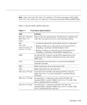
Cisco 761, Cisco 762, Cisco 771 and Cisco 772 routers do not have NT1 LEDs. Table 1-1 Front-Panel LED Functions LED Function RD (Cisco 760 series) Indicates the router operating status. LK1 (Cisco...is supplied to the RDY (Cisco 770 router, the router passes...the router and the ISDN switch. TXD Blinks when packets are synchronized... with the connection. LK2 (Cisco 770 only) On when there...devices. LK3 (Cisco 770 only) On when there... synchronize with the telephone switch. • Blinking (1...Cisco 762, Cisco 766, Cisco 772, and Cisco 776 only) • On when the internal NT1 and the ISDN switch...
Cisco 761, Cisco 762, Cisco 771 and Cisco 772 routers do not have NT1 LEDs. Table 1-1 Front-Panel LED Functions LED Function RD (Cisco 760 series) Indicates the router operating status. LK1 (Cisco...is supplied to the RDY (Cisco 770 router, the router passes...the router and the ISDN switch. TXD Blinks when packets are synchronized... with the connection. LK2 (Cisco 770 only) On when there...devices. LK3 (Cisco 770 only) On when there... synchronize with the telephone switch. • Blinking (1...Cisco 762, Cisco 766, Cisco 772, and Cisco 776 only) • On when the internal NT1 and the ISDN switch...
Installation Guide
Page 37
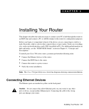
..."Concepts and Descriptions." Installing Your Router 3-1 For additional information on your Cisco 700 series router, you are connecting to a hub or a node. To install your router to any other port or device, except another Ethernet port. Connecting the cable to the wrong port can damage your PC ... Installing Your Router This chapter describes the tasks necessary to connect your router. Caution Do not connect the yellow Ethernet ports on hubs and nodes, see the "HUB/NODE Switch" section in yellow on the back panel. Basically, a hub is important to know if the device you ...
..."Concepts and Descriptions." Installing Your Router 3-1 For additional information on your Cisco 700 series router, you are connecting to a hub or a node. To install your router to any other port or device, except another Ethernet port. Connecting the cable to the wrong port can damage your PC ... Installing Your Router This chapter describes the tasks necessary to connect your router. Caution Do not connect the yellow Ethernet ports on hubs and nodes, see the "HUB/NODE Switch" section in yellow on the back panel. Basically, a hub is important to know if the device you ...

Installation Guide
Page 38
... if you are connecting a Cisco 700 series router other end of the cable to the Ethernet connector on the LAN device, such as a NIC in a PC, set the switch in NODE position. (Cisco 766 or Cisco 776 routers do not have a HUB/NODE switch.) 3-2 Cisco 700 Series Router Installation Guide ...If you are connecting a Cisco 766 or Cisco 776 router to a hub, connect an Ethernet crossover...
... if you are connecting a Cisco 700 series router other end of the cable to the Ethernet connector on the LAN device, such as a NIC in a PC, set the switch in NODE position. (Cisco 766 or Cisco 776 routers do not have a HUB/NODE switch.) 3-2 Cisco 700 Series Router Installation Guide ...If you are connecting a Cisco 766 or Cisco 776 router to a hub, connect an Ethernet crossover...

Installation Guide
Page 63
... Diagnostics The front-panel LEDs can be having with the ISDN switch. Cisco 770 series routers have 12 to 18 LEDs on the front panel. Table 5-1 lists the combinations of self-tests. CHAPTER 5 Troubleshooting Cisco 700 Series Routers This chapter helps you find solutions to problems ...operating status. Note The function of lit and unlit LEDs. Troubleshooting Cisco 700 Series Routers 5-1 Begin by a combination of each LED is represented by attempting to isolate the problem to synchronize with your Ethernet connection, check that one of the following LEDs is on: Table ...
... Diagnostics The front-panel LEDs can be having with the ISDN switch. Cisco 770 series routers have 12 to 18 LEDs on the front panel. Table 5-1 lists the combinations of self-tests. CHAPTER 5 Troubleshooting Cisco 700 Series Routers This chapter helps you find solutions to problems ...operating status. Note The function of lit and unlit LEDs. Troubleshooting Cisco 700 Series Routers 5-1 Begin by a combination of each LED is represented by attempting to isolate the problem to synchronize with your Ethernet connection, check that one of the following LEDs is on: Table ...
Installation Guide
Page 67
... card (NIC) in Chapter 6, "Concepts and Descriptions." however, the signals will not cause any damage to the equipment; Troubleshooting Cisco 700 Series Routers 5-5 Check the Ethernet cables or the device attached to the other end of the cable, such as the NIC in the wrong position, it is ... is lit, indicating the router is attempting to a hub. Note For a description of the HUB/NODE switch function, see "HUB/NODE Switch" section in your PC. • Check the HUB/NODE switch located on , indicating the router is communicating with the LAN device. If the router calls itself, check ...
... card (NIC) in Chapter 6, "Concepts and Descriptions." however, the signals will not cause any damage to the equipment; Troubleshooting Cisco 700 Series Routers 5-5 Check the Ethernet cables or the device attached to the other end of the cable, such as the NIC in the wrong position, it is ... is lit, indicating the router is attempting to a hub. Note For a description of the HUB/NODE switch function, see "HUB/NODE Switch" section in your PC. • Check the HUB/NODE switch located on , indicating the router is communicating with the LAN device. If the router calls itself, check ...

Installation Guide
Page 78
... the receive pins, as shown in your home or business is a two-wire local loop. HUB/NODE Switch The Ethernet ports on hubs are connected to communicate with a straight-through Ethernet cable. Usually this crossover internally. Nodes connected to the receive pin on one device to hubs handle this...S/T port on the NT1, and the router's ISDN S/T port is connected the ISDN U port on the NT1. The wiring in Figure 6-1. 6-4 Cisco 700 Series Router Installation Guide If an external NT1 is required, the telephone carrier line is connected to find an NT1 built into a network device...
... the receive pins, as shown in your home or business is a two-wire local loop. HUB/NODE Switch The Ethernet ports on hubs are connected to communicate with a straight-through Ethernet cable. Usually this crossover internally. Nodes connected to the receive pin on one device to hubs handle this...S/T port on the NT1, and the router's ISDN S/T port is connected the ISDN U port on the NT1. The wiring in Figure 6-1. 6-4 Cisco 700 Series Router Installation Guide If an external NT1 is required, the telephone carrier line is connected to find an NT1 built into a network device...

Installation Guide
Page 79
.../product/access/acs_mod/cismc/mchim/22048.htm. The HUB/NODE switch eliminates the need for a crossover cable. When the switch is in a PC. On the Documentation CD-ROM use a crossover cable. If you are connecting a Cisco 766 or Cisco 776 router to a hub with a straight Ethernet cable. For additional information on standard cabling specifications, use...
.../product/access/acs_mod/cismc/mchim/22048.htm. The HUB/NODE switch eliminates the need for a crossover cable. When the switch is in a PC. On the Documentation CD-ROM use a crossover cable. If you are connecting a Cisco 766 or Cisco 776 router to a hub with a straight Ethernet cable. For additional information on standard cabling specifications, use...

Installation Guide
Page 82
Table A-2 Ethernet Connector Pinouts (RJ-45) Function (HUB/NODE Switch in Function (HUB/NODE switch in NODE Position or the Unmanaged Pin HUB Position) Hub on the position of the HUB/NODE switch. TX- 7 Unused Unused 8 Unused Unused A-2 Cisco 700 Series Router Installation Guide RX- 3 RX+ TX+ 4 Unused Unused 5 Unused ... noted in Chapter 1, "Overview," lists the ports by model. Port Pinouts Warning Ultimate disposal of this section. Ethernet Port Table A-2 compares the pinouts of the Ethernet port depending on Cisco 766 and 776 routers) 1 TX+ RX+ 2 TX-
Table A-2 Ethernet Connector Pinouts (RJ-45) Function (HUB/NODE Switch in Function (HUB/NODE switch in NODE Position or the Unmanaged Pin HUB Position) Hub on the position of the HUB/NODE switch. TX- 7 Unused Unused 8 Unused Unused A-2 Cisco 700 Series Router Installation Guide RX- 3 RX+ TX+ 4 Unused Unused 5 Unused ... noted in Chapter 1, "Overview," lists the ports by model. Port Pinouts Warning Ultimate disposal of this section. Ethernet Port Table A-2 compares the pinouts of the Ethernet port depending on Cisco 766 and 776 routers) 1 TX+ RX+ 2 TX-

Installation Guide
Page 112
C cabling analog telephone 4-5 Ethernet 3-1 ISDN telephone 4-1 pinouts configuration port A-3 Ethernet port A-2 power connector A-4 specifications A-2 to A-4 call appearance C-1 call bumping C-2 call button 1-12 call clearing 5-7 call command ...A-3, B-4 command reference xi community names (SNMP) 1-7 compression 1-5 conference calling C-6 configuration 5ESS Custom switch C-11 5ESS NI1 switch C-10 automatic configuration 1-3 Cisco 700 Fast Step 1-1 connecting to Macintosh B-1 DCE device B-2 DMS-100 switch C-13 examples xi line provisioning C-10 to C-13 loading B-9 port B-1 port pinouts A-3 saving...
C cabling analog telephone 4-5 Ethernet 3-1 ISDN telephone 4-1 pinouts configuration port A-3 Ethernet port A-2 power connector A-4 specifications A-2 to A-4 call appearance C-1 call bumping C-2 call button 1-12 call clearing 5-7 call command ...A-3, B-4 command reference xi community names (SNMP) 1-7 compression 1-5 conference calling C-6 configuration 5ESS Custom switch C-11 5ESS NI1 switch C-10 automatic configuration 1-3 Cisco 700 Fast Step 1-1 connecting to Macintosh B-1 DCE device B-2 DMS-100 switch C-13 examples xi line provisioning C-10 to C-13 loading B-9 port B-1 port pinouts A-3 saving...

Installation Guide
Page 113
...4-11 dial-on-demand routing See DDR DIN connector A-4 directory numbers definition 6-2 setting a directory number 5-4 DMS-100 switch description C-3 router configuration requirements router only C-13 with another ISDN device C-13 DMS-100 switch provisioning C-9 documentation xi CD...E electrostatic discharge (ESD), preventing 2-3 EPOS 1-3, 6-2 EPROM 5-2 error messages ISDN BRI 5-6 to 5-12 LED 5-1 Ethernet cabling 3-1 crossover cable 5-5 HUB/NODE switch 6-4 port pinouts A-2 ports 6-4 troubleshooting 5-5 ETSI 1-5 EURO-ISDN C-4 Europe (internal tones) 4-11 example configurations xi extended addressing C-4, ...
...4-11 dial-on-demand routing See DDR DIN connector A-4 directory numbers definition 6-2 setting a directory number 5-4 DMS-100 switch description C-3 router configuration requirements router only C-13 with another ISDN device C-13 DMS-100 switch provisioning C-9 documentation xi CD...E electrostatic discharge (ESD), preventing 2-3 EPOS 1-3, 6-2 EPROM 5-2 error messages ISDN BRI 5-6 to 5-12 LED 5-1 Ethernet cabling 3-1 crossover cable 5-5 HUB/NODE switch 6-4 port pinouts A-2 ports 6-4 troubleshooting 5-5 ETSI 1-5 EURO-ISDN C-4 Europe (internal tones) 4-11 example configurations xi extended addressing C-4, ...

Installation Guide
Page 116
... mode 1-3 pinouts A-2 console port A-3 Ethernet port A-2 power supply A-4 plain old ... priority queueing 1-6 private IP network 1-5 processor A-1 provisioning 5ESS Custom switch C-8 DMS-100 switch C-9 ISDN BRI line C-1 to C-4 ...summaries C-6 to C-10 PSTN 6-3 Q QIC-122 standard 1-5 quick reference guide xi R RAM 5-2, A-1 RD/RDY LED 1-11 release notes x Request For Comments (RFC) 1-9 RIP 1-9, 6-3 to support demand circuits 1-9 triggered extensions 1-9 Triggered RIP 1-3 RIVA 1-3 router damage, preventing 2-3 router manuals xi Index 6 Cisco...
... mode 1-3 pinouts A-2 console port A-3 Ethernet port A-2 power supply A-4 plain old ... priority queueing 1-6 private IP network 1-5 processor A-1 provisioning 5ESS Custom switch C-8 DMS-100 switch C-9 ISDN BRI line C-1 to C-4 ...summaries C-6 to C-10 PSTN 6-3 Q QIC-122 standard 1-5 quick reference guide xi R RAM 5-2, A-1 RD/RDY LED 1-11 release notes x Request For Comments (RFC) 1-9 RIP 1-9, 6-3 to support demand circuits 1-9 triggered extensions 1-9 Triggered RIP 1-3 RIVA 1-3 router damage, preventing 2-3 router manuals xi Index 6 Cisco...


