Quick Start Guide
Page 1
Quick Start Guide Cisco Small Business SLM2048, SLM2024, SLM248G, SLM248P, SLM224G, SLM224P Smart Switch Package Contents • Smart Switch • Power Cord • Rubber feet • Quick Start Guide • Mounting Hardware • Product CD-ROM
Quick Start Guide Cisco Small Business SLM2048, SLM2024, SLM248G, SLM248P, SLM224G, SLM224P Smart Switch Package Contents • Smart Switch • Power Cord • Rubber feet • Quick Start Guide • Mounting Hardware • Product CD-ROM
Quick Start Guide
Page 2
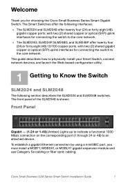
To establish a gigabit Ethernet connection by using a miniGBIC port, you for connecting the switch to the core network. Welcome Thank you must install a MGBT1, MGBSX1, or MGBLH1 gigabit expansion module and use Category 5e cabling or fiber optic cabling. The front panel of the SLM2048 is shown. Cisco Small Business SLM Series Smart Switch Installation Guide 1 This guide describes how to physically install your Smart Switch, connect network devices, and launch the Web-based configuration utility. 1 Getting to Know the Switch SLM2024...
To establish a gigabit Ethernet connection by using a miniGBIC port, you for connecting the switch to the core network. Welcome Thank you must install a MGBT1, MGBSX1, or MGBLH1 gigabit expansion module and use Category 5e cabling or fiber optic cabling. The front panel of the SLM2048 is shown. Cisco Small Business SLM Series Smart Switch Installation Guide 1 This guide describes how to physically install your Smart Switch, connect network devices, and launch the Web-based configuration utility. 1 Getting to Know the Switch SLM2024...
Quick Start Guide
Page 3
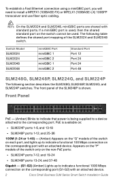
... Panel PoE - (Amber) Blinks to indicate that power is used, then the shared standard port on the switch cannot be used. NOTE On the SLM2024 and SLM2048, miniGBIC ports are shared with an attached device. PoE is shown. To establish a Fast Ethernet connection using a miniGBIC port, you will need to indicate a functional 1000 Mbps connection on the corresponding port (G1-G2) with an attached device. 2 Cisco Small Business SLM Series Smart Switch Installation Guide...
... Panel PoE - (Amber) Blinks to indicate that power is used, then the shared standard port on the switch cannot be used. NOTE On the SLM2024 and SLM2048, miniGBIC ports are shared with an attached device. PoE is shown. To establish a Fast Ethernet connection using a miniGBIC port, you will need to indicate a functional 1000 Mbps connection on the corresponding port (G1-G2) with an attached device. 2 Cisco Small Business SLM Series Smart Switch Installation Guide...
Quick Start Guide
Page 4
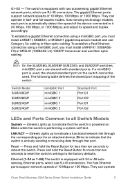
... autosensing gigabit Ethernet network ports, which use RJ-45 connectors. Switch Model SLM248G/P SLM248G/P SLM224G/P SLM224G/P miniGBIC Port miniGBIC 1 miniGBIC 2 miniGBIC 1 miniGBIC 2 Standard Port Port G1 Port G2 Port G1 Port G2 LEDs and Ports Common to all Switch Models System - (Green) Lights up to the factory defaults. If a miniGBIC port is powered on the switch cannot be used , the shared standard port on . Press and hold the Reset Button for less than ten seconds to reset the switch's settings to...
... autosensing gigabit Ethernet network ports, which use RJ-45 connectors. Switch Model SLM248G/P SLM248G/P SLM224G/P SLM224G/P miniGBIC Port miniGBIC 1 miniGBIC 2 miniGBIC 1 miniGBIC 2 Standard Port Port G1 Port G2 Port G1 Port G2 LEDs and Ports Common to all Switch Models System - (Green) Lights up to the factory defaults. If a miniGBIC port is powered on the switch cannot be used , the shared standard port on . Press and hold the Reset Button for less than ten seconds to reset the switch's settings to...
Quick Start Guide
Page 5
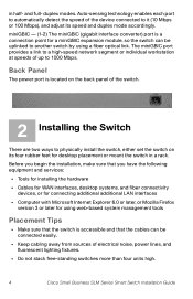
... physically install the switch, either set the switch on its speed and duplex mode accordingly. Back Panel The power port is accessible and that the switch is located on the back panel of the device connected to another switch by using a fiber optical link. Auto-sensing technology enables each port to automatically detect the speed of the switch. 2 Installing the Switch There are two ways to 1000 Mbps. and full- miniGBIC - (1-2) The miniGBIC (gigabit interface converter) port is a connection point...
... physically install the switch, either set the switch on its speed and duplex mode accordingly. Back Panel The power port is accessible and that the switch is located on the back panel of the device connected to another switch by using a fiber optical link. Auto-sensing technology enables each port to automatically detect the speed of the switch. 2 Installing the Switch There are two ways to 1000 Mbps. and full- miniGBIC - (1-2) The miniGBIC (gigabit interface converter) port is a connection point...
Quick Start Guide
Page 6
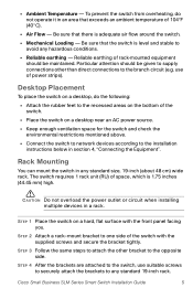
... installing multiple devices in any standard 19-inch rack. STEP 4 After the brackets are attached to the switch, use of the switch. • Place the switch on a desktop near an AC power source. • Keep enough ventilation space for the switch and check the environmental restrictions mentioned above. • Connect the switch to network devices according to the recessed areas on a hard, flat surface with the supplied...
... installing multiple devices in any standard 19-inch rack. STEP 4 After the brackets are attached to the switch, use of the switch. • Place the switch on a desktop near an AC power source. • Keep enough ventilation space for the switch and check the environmental restrictions mentioned above. • Connect the switch to network devices according to the recessed areas on a hard, flat surface with the supplied...
Quick Start Guide
Page 7
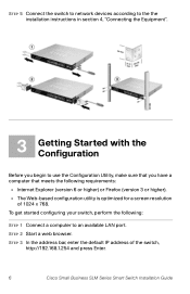
STEP 5 Connect the switch to network devices according to the the installation instructions in section 4, "Connecting the Equipment". 3 Getting Started with the Configuration Before you have a computer that you begin to an available LAN port. STEP 2 Start a web browser. To get started configuring your switch, perform the following: STEP 1 Connect a computer to use the Configuration Utility, make sure that meets the following requirements: • Internet Explorer (version 6 or higher) or Firefox (version 3 or higher). •...
STEP 5 Connect the switch to network devices according to the the installation instructions in section 4, "Connecting the Equipment". 3 Getting Started with the Configuration Before you have a computer that you begin to an available LAN port. STEP 2 Start a web browser. To get started configuring your switch, perform the following: STEP 1 Connect a computer to use the Configuration Utility, make sure that meets the following requirements: • Internet Explorer (version 6 or higher) or Firefox (version 3 or higher). •...
Quick Start Guide
Page 8
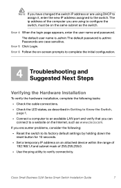
... user name and password. The ip address of 255.255.255.0. • Use the ping utility to the switch. The default password is admin. If you encounter problems, consider the following tasks: • Check the cable connections. • Check the LED states, as described in Getting to Know the Switch, page 1. • Connect a computer to an available LAN port and verify that you can connect to its factory default settings by holding down the reset button...
... user name and password. The ip address of 255.255.255.0. • Use the ping utility to the switch. The default password is admin. If you encounter problems, consider the following tasks: • Check the cable connections. • Check the LED states, as described in Getting to Know the Switch, page 1. • Connect a computer to an available LAN port and verify that you can connect to its factory default settings by holding down the reset button...

Quick Start Guide
Page 9
... Smart Switch Administration Guide. Check for the latest version of software to ensure your current configuration settings from unauthorized access. • Visit the software downloads area at http://tools.cisco.com/support/ downloads and navigate to start using your switch by using a different computer. Consider taking some hardware problems if the second computer also fails to establish a link, please contact technical support for detailed configuration of the switch. • Change the default password of the firmware. • Review additional documentation...
... Smart Switch Administration Guide. Check for the latest version of software to ensure your current configuration settings from unauthorized access. • Visit the software downloads area at http://tools.cisco.com/support/ downloads and navigate to start using your switch by using a different computer. Consider taking some hardware problems if the second computer also fails to establish a link, please contact technical support for detailed configuration of the switch. • Change the default password of the firmware. • Review additional documentation...
Quick Start Guide
Page 10
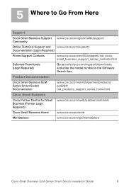
... Home www.cisco.com/smb Marketplace www.cisco.com/go /smallbizsupport Community Online Technical Support and www.cisco.com/support Documentation (Login Required) Phone Support Contacts www.cisco.com/en/US/support/tsd_cisco_ small_business_support_center_contacts.html Software Downloads (Login Required) Go to Go From Here Support Cisco Small Business Support www.cisco.com/go /marketplace Cisco Small Business SLM Series Smart Switch Installation Guide 9 5 Where to tools.cisco.com/support/downloads, and enter the model number in the Software Search...
... Home www.cisco.com/smb Marketplace www.cisco.com/go /smallbizsupport Community Online Technical Support and www.cisco.com/support Documentation (Login Required) Phone Support Contacts www.cisco.com/en/US/support/tsd_cisco_ small_business_support_center_contacts.html Software Downloads (Login Required) Go to Go From Here Support Cisco Small Business Support www.cisco.com/go /marketplace Cisco Small Business SLM Series Smart Switch Installation Guide 9 5 Where to tools.cisco.com/support/downloads, and enter the model number in the Software Search...
Quick Start Guide
Page 12
...; 2009 Cisco Systems, Inc. The use of the word partner does not imply a partnership relationship between Cisco and any other trademarks mentioned in the United States and certain other countries. Americas Headquarters Cisco Systems, Inc. 170 West Tasman Drive San Jose, CA 95134-1706 USA http://www.cisco.com Tel...: 408 526-4000 800 553-NETS (6387) Fax: 408 527-0883 Cisco, Cisco Systems, the Cisco logo, and the Cisco Systems logo are the property of their respective owners. and/or its affiliates in this document or Website are registered trademarks ...
...; 2009 Cisco Systems, Inc. The use of the word partner does not imply a partnership relationship between Cisco and any other trademarks mentioned in the United States and certain other countries. Americas Headquarters Cisco Systems, Inc. 170 West Tasman Drive San Jose, CA 95134-1706 USA http://www.cisco.com Tel...: 408 526-4000 800 553-NETS (6387) Fax: 408 527-0883 Cisco, Cisco Systems, the Cisco logo, and the Cisco Systems logo are the property of their respective owners. and/or its affiliates in this document or Website are registered trademarks ...


