
User Guide
Page 2
...of the address because most current web browsers do not require it is a registered trademark or trademark of Cisco Systems, Inc. WEB: This globe icon indicates a noteworthy website address or e-mail address. WebView Switches About This Guide ii and certain other countries. All rights reserved. About This Guide Icon Descriptions While ...com/glossary Network Security www.linksys.com/security Copyright and Trademarks Linksys is something that could damage your property or product. Copyright © 2008 Cisco Systems, Inc. and/ or its affiliates in front of the web address.
...of the address because most current web browsers do not require it is a registered trademark or trademark of Cisco Systems, Inc. WEB: This globe icon indicates a noteworthy website address or e-mail address. WebView Switches About This Guide ii and certain other countries. All rights reserved. About This Guide Icon Descriptions While ...com/glossary Network Security www.linksys.com/security Copyright and Trademarks Linksys is something that could damage your property or product. Copyright © 2008 Cisco Systems, Inc. and/ or its affiliates in front of the web address.

User Guide
Page 3
... 4 Front Panel 4 LEDs 4 The Back Panel 4 SRW248G4 5 Front Panel 5 LEDs 5 Back Panel 5 SRW224G4 6 Front Panel 6 LEDs 6 Back Panel 6 Chapter 3: Connecting the Switch 8 Overview 8 Placement Options 8 Desktop Placement 8 Rack-Mount Placement 8 Hardware Installation 9 Configuring the Switch 9 Chapter 4: Configuration Using the Console Interface 10 Overview 10 Configuring the HyperTerminal Application 10 Connecting to the...
... 4 Front Panel 4 LEDs 4 The Back Panel 4 SRW248G4 5 Front Panel 5 LEDs 5 Back Panel 5 SRW224G4 6 Front Panel 6 LEDs 6 Back Panel 6 Chapter 3: Connecting the Switch 8 Overview 8 Placement Options 8 Desktop Placement 8 Rack-Mount Placement 8 Hardware Installation 9 Configuring the Switch 9 Chapter 4: Configuration Using the Console Interface 10 Overview 10 Configuring the HyperTerminal Application 10 Connecting to the...

User Guide
Page 4
WebView Switches Table of Contents Chapter 5: Advanced Configuration 20 Overview 20 Accessing the Web-based Utility 20 Setup > Summary 20 Device Information 20 System Information 21 Setup > ...
WebView Switches Table of Contents Chapter 5: Advanced Configuration 20 Overview 20 Accessing the Web-based Utility 20 Setup > Summary 20 Device Information 20 System Information 21 Setup > ...

User Guide
Page 5
WebView Switches Table of Contents Security > RADIUS 36 Security > TACACS 37 Security > 802.1x Settings 37 802.1x Settings > Setting Timer 38 Security > Port Security 38 Security > ...
WebView Switches Table of Contents Security > RADIUS 36 Security > TACACS 37 Security > 802.1x Settings 37 802.1x Settings > Setting Timer 38 Security > Port Security 38 Security > ...

User Guide
Page 6
WebView Switches Table of Contents Admin > Static Address 56 Query 56 Admin > Dynamic Address 57 Query 57 Admin > Logging 57 Admin > Port Mirroring 58 Admin > Cable Test ...
WebView Switches Table of Contents Admin > Static Address 56 Query 56 Admin > Dynamic Address 57 Query 57 Admin > Logging 57 Admin > Port Mirroring 58 Admin > Cable Test ...

User Guide
Page 7
Table of Contents User Information for Consumer Products Covered by EU Directive 2002/96/EC on Waste Electric and Electronic Equipment (WEEE 78 Appendix H: Software License Agreement 82 Software in Linksys Products 82 Software Licenses 82 Schedule 1 Linksys Software License Agreement 82 Schedule 2 83 Schedule 3 86 Appendix I: Contact Information 89 WebView Switches v
Table of Contents User Information for Consumer Products Covered by EU Directive 2002/96/EC on Waste Electric and Electronic Equipment (WEEE 78 Appendix H: Software License Agreement 82 Software in Linksys Products 82 Software Licenses 82 Schedule 1 Linksys Software License Agreement 82 Schedule 2 83 Schedule 3 86 Appendix I: Contact Information 89 WebView Switches v

User Guide
Page 8
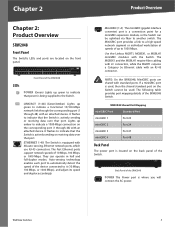
...one of the system. IGMP Snooping limits bandwidth-intensive video traffic to only the requestors without flooding to all models, the name WebView Switch will be setup. This also provides a level of reliability in your network. 1 Configuration of traffic on regular traffic. The rich management... 24 10/100/1000 RJ-45 ports and 2 shared SFP (MiniGBIC) slots. •• SRW2016 16-Port 10/100/1000 Gigabit Switch with WebView. Individual users or applications can be prioritized above others using a RADIUS authentication mechanism and can be controlled using SSL for realtime ...
...one of the system. IGMP Snooping limits bandwidth-intensive video traffic to only the requestors without flooding to all models, the name WebView Switch will be setup. This also provides a level of reliability in your network. 1 Configuration of traffic on regular traffic. The rich management... 24 10/100/1000 RJ-45 ports and 2 shared SFP (MiniGBIC) slots. •• SRW2016 16-Port 10/100/1000 Gigabit Switch with WebView. Individual users or applications can be prioritized above others using a RADIUS authentication mechanism and can be controlled using SSL for realtime ...
User Guide
Page 9
...on the front panel. The MGBSX1 and the MGBLH1 require fiber cabling with LC connectors, while the MGBT1 requires a Category 5e Ethernet cable with the Switch. Back Panel of the device connected to indicate that port. Lights up green to it (10 Mbps, 100 Mbps, or 1000 Mbps), and ... 4 Standard Port Port 23 Port 24 Port 47 Port 48 Back Panel The power port is a connection point for a miniGBIC expansion module, so the Switch can operate in half and full-duplex modes. LINK/ACT (1-48) (Green/Amber) Lights up to indicate a functional 10/100-Mbps network link through ...
...on the front panel. The MGBSX1 and the MGBLH1 require fiber cabling with LC connectors, while the MGBT1 requires a Category 5e Ethernet cable with the Switch. Back Panel of the device connected to indicate that port. Lights up green to it (10 Mbps, 100 Mbps, or 1000 Mbps), and ... 4 Standard Port Port 23 Port 24 Port 47 Port 48 Back Panel The power port is a connection point for a miniGBIC expansion module, so the Switch can operate in half and full-duplex modes. LINK/ACT (1-48) (Green/Amber) Lights up to indicate a functional 10/100-Mbps network link through ...

User Guide
Page 10
... Mbps. Auto-sensing technology enables each port to automatically detect the speed of the SRW2024 LEDs POWER (Green) Lights up to manage the Switch using the provided serial cable. The MGBSX1 and the MGBLH1 require fiber cabling with LC connectors, while the MGBT1 requires a Category 5e Ethernet.... NOTE: On the SRW2024, MiniGBIC ports are located on the front panel. They can use RJ-45 connectors. Chapter 2 Product Overview CONSOLE The Switch is used . Wait a few seconds and then reconnect it (10 Mbps, 100 Mbps, or 1000 Mbps), and adjust its speed and duplex accordingly...
... Mbps. Auto-sensing technology enables each port to automatically detect the speed of the SRW2024 LEDs POWER (Green) Lights up to manage the Switch using the provided serial cable. The MGBSX1 and the MGBLH1 require fiber cabling with LC connectors, while the MGBT1 requires a Category 5e Ethernet.... NOTE: On the SRW2024, MiniGBIC ports are located on the front panel. They can use RJ-45 connectors. Chapter 2 Product Overview CONSOLE The Switch is used . Wait a few seconds and then reconnect it (10 Mbps, 100 Mbps, or 1000 Mbps), and adjust its speed and duplex accordingly...

User Guide
Page 11
... purposes) using the console port. The MiniGBIC port provides a link to a computer's serial port (for a miniGBIC expansion module, so the Switch can use RJ-45 connectors. If a miniGBIC port is actively sending or receiving data over that allows you will connect the AC power. NOTE... (1 through 16) with standard ports. NOTE: On the SRW2016, MiniGBIC ports are located on the back of the SRW2016 Switch. Back Panel of the Switch. CONSOLE The Switch is a connection point for configuration purposes) using the console port. LINK/ACT (1-16) (Green) Lights up to Chapter...
... purposes) using the console port. The MiniGBIC port provides a link to a computer's serial port (for a miniGBIC expansion module, so the Switch can use RJ-45 connectors. If a miniGBIC port is actively sending or receiving data over that allows you will connect the AC power. NOTE... (1 through 16) with standard ports. NOTE: On the SRW2016, MiniGBIC ports are located on the back of the SRW2016 Switch. Back Panel of the Switch. CONSOLE The Switch is a connection point for configuration purposes) using the console port. LINK/ACT (1-16) (Green) Lights up to Chapter...

User Guide
Page 12
...to indicate a functional 10/100Mbps network link through the corresponding port (G1 through 48) with an attached device. WebView Switches ETHERNET G1-G4 The Switch is actively sending or receiving data over that port. They can operate in half and full-duplex modes. The MGBSX1 ...Gigabit Ethernet ports. Chapter 2 Product Overview NOTE: If you will connect the AC power. 5 SRW248G4 Front Panel The Switch's LEDs and ports are shared with the Switch. MiniGBIC (1-2) The miniGBIC (gigabit interface converter) port is used, then the shared Gigabit Ethernet port on the front ...
...to indicate a functional 10/100Mbps network link through the corresponding port (G1 through 48) with an attached device. WebView Switches ETHERNET G1-G4 The Switch is actively sending or receiving data over that port. They can operate in half and full-duplex modes. The MGBSX1 ...Gigabit Ethernet ports. Chapter 2 Product Overview NOTE: If you will connect the AC power. 5 SRW248G4 Front Panel The Switch's LEDs and ports are shared with the Switch. MiniGBIC (1-2) The miniGBIC (gigabit interface converter) port is used, then the shared Gigabit Ethernet port on the front ...

User Guide
Page 13
... miniGBIC modules with an RJ-45 connector. Refer to Chapter 4: Configuration Using the Console Interface for a miniGBIC expansion module, so the Switch can use HyperTerminal to indicate a functional 10/100-Mbps network link through the corresponding port (G1 through 24) with an attached device.... ETHERNET G1-G4 The Switch is equipped with 4 auto-sensing Gigabit Ethernet network ports, which use RJ-45 connectors. SRW224G4 Shared Port Mapping miniGBIC Port miniGBIC 1 ...
... miniGBIC modules with an RJ-45 connector. Refer to Chapter 4: Configuration Using the Console Interface for a miniGBIC expansion module, so the Switch can use HyperTerminal to indicate a functional 10/100-Mbps network link through the corresponding port (G1 through 24) with an attached device.... ETHERNET G1-G4 The Switch is equipped with 4 auto-sensing Gigabit Ethernet network ports, which use RJ-45 connectors. SRW224G4 Shared Port Mapping miniGBIC Port miniGBIC 1 ...

User Guide
Page 14
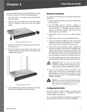
... the AC power. Chapter 2 POWER The Power port is equipped with a serial port labeled Console (located on the back of the Switch. Wait a few seconds and then reconnect it. Refer to Chapter 4: Configuration Using the Console Interface for configuration purposes) using the console ...port. Product Overview WebView Switches 7 CONSOLE The Switch is where you need to reset the Switch, unplug the power cord from the back of the switch) that allows you to connect to manage the Switch using the provided serial cable. You can use HyperTerminal...
... the AC power. Chapter 2 POWER The Power port is equipped with a serial port labeled Console (located on the back of the Switch. Wait a few seconds and then reconnect it. Refer to Chapter 4: Configuration Using the Console Interface for configuration purposes) using the console ...port. Product Overview WebView Switches 7 CONSOLE The Switch is where you need to reset the Switch, unplug the power cord from the back of the switch) that allows you to connect to manage the Switch using the provided serial cable. You can use HyperTerminal...

User Guide
Page 15
... you connect your network devices, make sure you don't exceed the maximum cabling distances, which are placing the Switch. •• Connect the Switch to network devices according to supply connections other than the room ambient temperature. Appropriate consideration of equipment nameplate ratings ... ambient temperature of the rack environment may be greater than direct connections to the branch circuit (for desktop placement or mount the switch in the rack should be easily connected. •• Keep cabling away from sources of electrical noise, power lines, and fluorescent...
... you connect your network devices, make sure you don't exceed the maximum cabling distances, which are placing the Switch. •• Connect the Switch to network devices according to supply connections other than the room ambient temperature. Appropriate consideration of equipment nameplate ratings ... ambient temperature of the rack environment may be greater than direct connections to the branch circuit (for desktop placement or mount the switch in the rack should be easily connected. •• Keep cabling away from sources of electrical noise, power lines, and fluorescent...
User Guide
Page 16
..., then connect the miniGBIC module to a PC or other end to the miniGBIC port. Make sure all the devices you need to the Switch's Console port, and tighten the captive retaining screws. For 10/100-Mbps devices, connect a Category 5 Ethernet network cable to one of... a different power cord could damage the Switch. 8. Each active port's corresponding Link/Act LED will also light up on the network devices connected to the Hardware Installation instructions below . 1. ...
..., then connect the miniGBIC module to a PC or other end to the miniGBIC port. Make sure all the devices you need to the Switch's Console port, and tighten the captive retaining screws. For 10/100-Mbps devices, connect a Category 5 Ethernet network cable to one of... a different power cord could damage the Switch. 8. Each active port's corresponding Link/Act LED will also light up on the network devices connected to the Hardware Installation instructions below . 1. ...
User Guide
Page 17
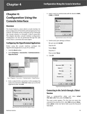
... Connect To Screen 5. Start > Programs > Accessories > Communications > HyperTerminal 3. HyperTerminal Connection Description Screen WebView Switches HyperTerminal Properties Screen Connecting to communicate with the Switch: COM1, COM2, or TCP/IP. Leave the Password field blank. 10 Chapter 4 Configuration Using the Console... admin in the next chapter. Click the Start button. 2. Select a port to the Switch through the web utility, which is SRW2048. The Switch can also be configured using the console interface, configure the HyperTerminal application on your network. ...
... Connect To Screen 5. Start > Programs > Accessories > Communications > HyperTerminal 3. HyperTerminal Connection Description Screen WebView Switches HyperTerminal Properties Screen Connecting to communicate with the Switch: COM1, COM2, or TCP/IP. Leave the Password field blank. 10 Chapter 4 Configuration Using the Console... admin in the next chapter. Click the Start button. 2. Select a port to the Switch through the web utility, which is SRW2048. The Switch can also be configured using the console interface, configure the HyperTerminal application on your network. ...

User Guide
Page 18
... the highlighted option. File Management 7. Restore System Default Settings 8. Reboot System 9. You select a menu option when you can check the Switch's firmware versions and general system information. The bottom of menus. Port Configuration 4. Security Settings 5. Back to open CLI interface. Use the... selection. Menu options and any values entered or present will be highlighted. Help 5. System Configuration Menu Switch Main Menu WebView Switches 11 Chapter 4 Configuration Using the Console Interface Telnet Login Screen Press the Esc button to return to the login ...
... the highlighted option. File Management 7. Restore System Default Settings 8. Reboot System 9. You select a menu option when you can check the Switch's firmware versions and general system information. The bottom of menus. Port Configuration 4. Security Settings 5. Back to open CLI interface. Use the... selection. Menu options and any values entered or present will be highlighted. Help 5. System Configuration Menu Switch Main Menu WebView Switches 11 Chapter 4 Configuration Using the Console Interface Telnet Login Screen Press the Esc button to return to the login ...

User Guide
Page 19
... Port Configuration Select Edit and press the Enter key to make changes. To exit, select Quit and press the Enter key. WebView Switches 12 Select Save and press the Enter key to the Action menu. Toggle to the desired speed and when your changes are complete... Session Configuration •• Secure Telnet (SSH) Configuration. Versions General System Information The General System Information screen displays general information about the Switch. When your changes are complete, press the Esc key to return to save your changes. Select Save and press the Enter key to...
... Port Configuration Select Edit and press the Enter key to make changes. To exit, select Quit and press the Enter key. WebView Switches 12 Select Save and press the Enter key to the Action menu. Toggle to the desired speed and when your changes are complete... Session Configuration •• Secure Telnet (SSH) Configuration. Versions General System Information The General System Information screen displays general information about the Switch. When your changes are complete, press the Esc key to return to save your changes. Select Save and press the Enter key to...
User Guide
Page 20
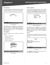
.... To exit, select Quit and press the Enter key. SSH Server Configuration On the SSH Server Configuration screen, you may enter a value of 0 sec. WebView Switches 13 Chapter 4 Configuration Using the Console Interface Telnet Configuration The Telnet Configuration screen displays the timeout value. Select Save and press the Enter key to...
.... To exit, select Quit and press the Enter key. SSH Server Configuration On the SSH Server Configuration screen, you may enter a value of 0 sec. WebView Switches 13 Chapter 4 Configuration Using the Console Interface Telnet Configuration The Telnet Configuration screen displays the timeout value. Select Save and press the Enter key to...
User Guide
Page 21
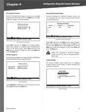
...press the Enter key. Security Settings The Security Settings screen enables you can administer the user names and passwords of those accessing the Switch. Select Save and press the Enter key to make changes. Username & Password Settings Select Edit and press the Enter key to...save your changes. NOTE: The Username & Password Settings screen can toggle between RSA and DSA using the SPACE bar. Security Settings WebView Switches 14 Chapter 4 Configuration Using the Console Interface SSH Crypto Key Generation On the SSH Crypto Key Generation screen, you can also be modified....
...press the Enter key. Security Settings The Security Settings screen enables you can administer the user names and passwords of those accessing the Switch. Select Save and press the Enter key to make changes. Username & Password Settings Select Edit and press the Enter key to...save your changes. NOTE: The Username & Password Settings screen can toggle between RSA and DSA using the SPACE bar. Security Settings WebView Switches 14 Chapter 4 Configuration Using the Console Interface SSH Crypto Key Generation On the SSH Crypto Key Generation screen, you can also be modified....


