
Administration Guide
Page 10
... Defining SNMP Filter Settings Managing Cisco Discovery Protocol Chapter : Managing System Files Software Upgrade Save Configuration Copy Configuration Via TFTP Via HTTP Active Image DHCP Auto Configuration Chapter : Managing Power-over-Ethernet Devices Defining PoE Settings Chapter : Managing System Logs Enabling System Logs Viewing the Device Memory Logs Clearing Message Logs Viewing the System Flash Logs Clearing Flash Logs Remote Log Servers Modifying Syslog Server Settings Chapter : Viewing Statistics Viewing Ethernet Statistics Defining Interface Statistics Resetting Interface Statistics...
... Defining SNMP Filter Settings Managing Cisco Discovery Protocol Chapter : Managing System Files Software Upgrade Save Configuration Copy Configuration Via TFTP Via HTTP Active Image DHCP Auto Configuration Chapter : Managing Power-over-Ethernet Devices Defining PoE Settings Chapter : Managing System Logs Enabling System Logs Viewing the Device Memory Logs Clearing Message Logs Viewing the System Flash Logs Clearing Flash Logs Remote Log Servers Modifying Syslog Server Settings Chapter : Viewing Statistics Viewing Ethernet Statistics Defining Interface Statistics Resetting Interface Statistics...
Administration Guide
Page 17
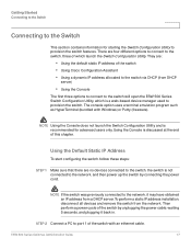
... a power cycle of which is recommended for starting the Switch Configuration Utility to the network, it back in. ESW 500 Series Switches Administration Guide 17 NOTE Using the Console does not launch the Switch Configuration Utility and is a web-based device manager used to the switch via DHCP (from the network. There are : • Using the default static IP address of the switch with Windows) or Putty (freeware). STEP 2 Connect a PC to port 1 of the switch • Using Cisco Configuration Assistant...
... a power cycle of which is recommended for starting the Switch Configuration Utility to the network, it back in. ESW 500 Series Switches Administration Guide 17 NOTE Using the Console does not launch the Switch Configuration Utility and is a web-based device manager used to the switch via DHCP (from the network. There are : • Using the default static IP address of the switch with Windows) or Putty (freeware). STEP 2 Connect a PC to port 1 of the switch • Using Cisco Configuration Assistant...
Administration Guide
Page 24
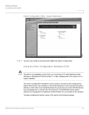
... network. System Dashboard STEP 5 You are now ready to the Switch Switch Configuration Utility - To begin installing the switch using CCA, you must have a PC with Windows Vista Ultimate or Windows XP, Service Pack 1 or later installed and CCA version 2.2 or higher installed. Using the Cisco Configuration Assistant (CCA) NOTE To perform an installation using CCA, perform the following steps: ESW 500 Series Switches Administration Guide 24 Getting Started Connecting to proceed with additional switch configuration...
... network. System Dashboard STEP 5 You are now ready to the Switch Switch Configuration Utility - To begin installing the switch using CCA, you must have a PC with Windows Vista Ultimate or Windows XP, Service Pack 1 or later installed and CCA version 2.2 or higher installed. Using the Cisco Configuration Assistant (CCA) NOTE To perform an installation using CCA, perform the following steps: ESW 500 Series Switches Administration Guide 24 Getting Started Connecting to proceed with additional switch configuration...
Administration Guide
Page 32
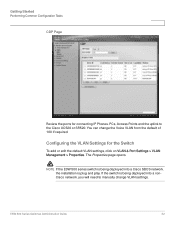
... connecting IP Phones, PCs, Access Points and the uplink to manually change the Voice VLAN from the default of 100 if required. NOTE If the ESW 500 series switch is being deployed into a Cisco SBCS network, the installation is being deployed into a nonCisco network, you will need to the Cisco UC520 or SR520. Getting Started Performing Common Configuration Tasks CDP Page Review the ports for the Switch To add or edit the default VLAN settings, click on VLAN & Port Settings > VLAN Management...
... connecting IP Phones, PCs, Access Points and the uplink to manually change the Voice VLAN from the default of 100 if required. NOTE If the ESW 500 series switch is being deployed into a Cisco SBCS network, the installation is being deployed into a nonCisco network, you will need to the Cisco UC520 or SR520. Getting Started Performing Common Configuration Tasks CDP Page Review the ports for the Switch To add or edit the default VLAN settings, click on VLAN & Port Settings > VLAN Management...
Administration Guide
Page 70
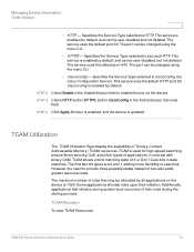
... view TCAM Resources: ESW 500 Series Switches Administration Guide 70 Specifies the Service Type selected is updated. However, the need to enable Bonjour on the device is enabled by all applications on the device. The first two bit types are 0 and 1, adding more flexibility to searches. Managing Device Information TCAM Utilization - This service is 1024. The port can be changed using the menu CLI. - Bonjour is enabled, and the device is secured...
... view TCAM Resources: ESW 500 Series Switches Administration Guide 70 Specifies the Service Type selected is updated. However, the need to enable Bonjour on the device is enabled by all applications on the device. The first two bit types are 0 and 1, adding more flexibility to searches. Managing Device Information TCAM Utilization - This service is 1024. The port can be changed using the menu CLI. - Bonjour is enabled, and the device is secured...
Administration Guide
Page 72
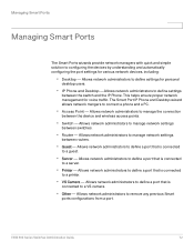
... to a server. • Printer - Allows network administrators to define a port that is connected to manage network settings between routers. • Guest - This helps ensure proper network management for personal desktop users. • IP Phone and Desktop -Allows network administrators to manage network settings between switches. • Router - Allows network administrators to define settings between the device and wireless access points. • Switch - Allows network administrators to define settings for voice traffic. Allows network administrators to define a port that is...
... to a server. • Printer - Allows network administrators to define a port that is connected to manage network settings between routers. • Guest - This helps ensure proper network management for personal desktop users. • IP Phone and Desktop -Allows network administrators to manage network settings between switches. • Router - Allows network administrators to define settings between the device and wireless access points. • Switch - Allows network administrators to define settings for voice traffic. Allows network administrators to define a port that is...
Administration Guide
Page 77
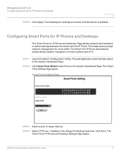
... range of ports. Click Next. The web application automatically opens to the System Dashboard Page. STEP 4 Select IP Phone + Desktop in the Assign Profile drop-down list. Managing Smart Ports Configuring Smart Ports for voice traffic. STEP 1 Open the Switch Configuration Utility. The Smart Ports IP Phones and Desktop Settings Page opens: ESW 500 Series Switches Administration Guide 77 The Desktop port settings are saved, and the device is updated. This helps ensure proper network management for IP Phones...
... range of ports. Click Next. The web application automatically opens to the System Dashboard Page. STEP 4 Select IP Phone + Desktop in the Assign Profile drop-down list. Managing Smart Ports Configuring Smart Ports for voice traffic. STEP 1 Open the Switch Configuration Utility. The Smart Ports IP Phones and Desktop Settings Page opens: ESW 500 Series Switches Administration Guide 77 The Desktop port settings are saved, and the device is updated. This helps ensure proper network management for IP Phones...
Administration Guide
Page 93
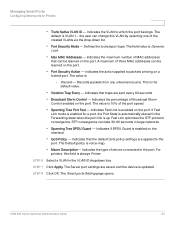
... MAC addresses that can take 30-60 seconds in the Forwarding state when the port link is always Printer. STP convergence can be learned on the port. ESW 500 Series Switches Administration Guide 93 the user can be learned on the port. Indicates the maximum number of the created VLANs via the drop down list. • Port Security Mode - Indicates that the default QoS policy settings are applied to the port. The Server port settings...
... MAC addresses that can take 30-60 seconds in the Forwarding state when the port link is always Printer. STP convergence can be learned on the port. ESW 500 Series Switches Administration Guide 93 the user can be learned on the port. Indicates the maximum number of the created VLANs via the drop down list. • Port Security Mode - Indicates that the default QoS policy settings are applied to the port. The Server port settings...
Administration Guide
Page 117
... login and via user names and user-defined passwords. • Authorization - The TACACS server checks the user privileges. Configuring Device Security Defining Authentication Defining TACACS+ The devices provide Terminal Access Controller Access Control System (TACACS+) client support. If default values are not defined, the system defaults are applied to the new TACACS+ new servers. To define TACACS+: ESW 500 Series Switches Administration Guide 117 The TACACS+ default parameters are user-assigned defaults. TACACS+ provides the following services...
... login and via user names and user-defined passwords. • Authorization - The TACACS server checks the user privileges. Configuring Device Security Defining Authentication Defining TACACS+ The devices provide Terminal Access Controller Access Control System (TACACS+) client support. If default values are not defined, the system defaults are applied to the new TACACS+ new servers. To define TACACS+: ESW 500 Series Switches Administration Guide 117 The TACACS+ default parameters are user-assigned defaults. TACACS+ provides the following services...

Administration Guide
Page 139
... ESW 520 devices, sets the Unknown Unicast Control as the Broadcast Mode globally defined on the specific interface. Assigns the copied storm control configuration to be forwarded. Enables Broadcast packet types to the specified table entry. • Port - This is enabled. • Enable Broadcast Control - Indicates if Broadcast packet types are : - ESW 500 Series Switches Administration Guide 139 Enable - The range rate is 3500100,000 Kbps. • Copy From Entry Number - Configuring Device Security Defining Traffic Control STEP 1 Click Security > Traffic Control > Storm...
... ESW 520 devices, sets the Unknown Unicast Control as the Broadcast Mode globally defined on the specific interface. Assigns the copied storm control configuration to be forwarded. Enables Broadcast packet types to the specified table entry. • Port - This is enabled. • Enable Broadcast Control - Indicates if Broadcast packet types are : - ESW 500 Series Switches Administration Guide 139 Enable - The range rate is 3500100,000 Kbps. • Copy From Entry Number - Configuring Device Security Defining Traffic Control STEP 1 Click Security > Traffic Control > Storm...
Administration Guide
Page 143
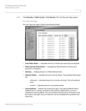
... security status. The possible field values are : ESW 500 Series Switches Administration Guide 143 Indicates the port is currently locked. • Learning Mode - In order to change the Learning Mode, the Lock Interface must be reinstated.The possible field values are : - Configuring Device Security Defining Traffic Control STEP 1 Click Security > Traffic Control > Port Security. Indicates the Port on which port security is configured. • EtherChannels Radio Button - Unlocked - Defines the locked port type. The Port Security Page opens: Port Security Page The Port Security...
... security status. The possible field values are : ESW 500 Series Switches Administration Guide 143 Indicates the port is currently locked. • Learning Mode - In order to change the Learning Mode, the Lock Interface must be reinstated.The possible field values are : - Configuring Device Security Defining Traffic Control STEP 1 Click Security > Traffic Control > Port Security. Indicates the Port on which port security is configured. • EtherChannels Radio Button - Unlocked - Defines the locked port type. The Port Security Page opens: Port Security Page The Port Security...
Administration Guide
Page 146
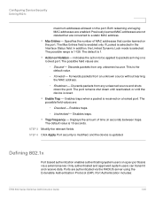
... is reset. • Enable Trap - The possible field values are : - The default value is the default value. - Only authenticated and approved system users can be applied to be learned on Violation - Ports are authenticated via a external server. Configuring Device Security Defining 802.1x maximum addresses allowed on a per-port basis via the RADIUS server using the Extensible Authentication Protocol (EAP). Port Authentication includes: ESW 500 Series Switches Administration Guide...
... is reset. • Enable Trap - The possible field values are : - The default value is the default value. - Only authenticated and approved system users can be applied to be learned on Violation - Ports are authenticated via a external server. Configuring Device Security Defining 802.1x maximum addresses allowed on a per-port basis via the RADIUS server using the Extensible Authentication Protocol (EAP). Port Authentication includes: ESW 500 Series Switches Administration Guide...
Administration Guide
Page 214
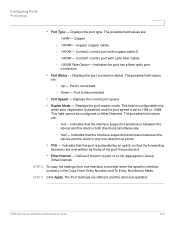
... when auto negotiation is disabled, and the port speed is part of the port that this port is disconnected. • Port Speed - Displays the port type. ESW 500 Series Switches Administration Guide 214 The possible field values are : - Half - STEP 3 Click Apply. Up - Down - Configuring Ports Port Settings • Port Type - The possible field values are overwritten by those of a Link Aggregation Group (EtherChannel). Defines if the port is set to another, enter the specific interface numbers...
... when auto negotiation is disabled, and the port speed is part of the port that this port is disconnected. • Port Speed - Displays the port type. ESW 500 Series Switches Administration Guide 214 The possible field values are : - Half - STEP 3 Click Apply. Up - Down - Configuring Ports Port Settings • Port Type - The possible field values are overwritten by those of a Link Aggregation Group (EtherChannel). Defines if the port is set to another, enter the specific interface numbers...
Administration Guide
Page 269
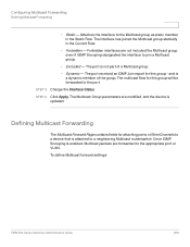
... group will be forwarded to a neighboring Multicast router/switch. STEP 3 Change the Interface Status. Static - Attaches the interface to join a Multicast group. - The port is a dynamic member of a Multicast group. - and is not part of the group. Defining Multicast Forwarding The Multicast Forward Page contains fields for this group - Forbidden - The multicast flow for attaching ports or EtherChannels to a device that is attached to the port. Dynamic - STEP 4 Click Apply. To define Multicast forward settings: ESW 500 Series Switches Administration Guide...
... group will be forwarded to a neighboring Multicast router/switch. STEP 3 Change the Interface Status. Static - Attaches the interface to join a Multicast group. - The port is a dynamic member of a Multicast group. - and is not part of the group. Defining Multicast Forwarding The Multicast Forward Page contains fields for this group - Forbidden - The multicast flow for attaching ports or EtherChannels to a device that is attached to the port. Dynamic - STEP 4 Click Apply. To define Multicast forward settings: ESW 500 Series Switches Administration Guide...
Administration Guide
Page 312
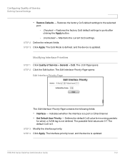
... the device is not defined. Indicates whether the interface is 0. Configuring Quality of Service > General > CoS. Maintains the current QoS settings. The default CoS is a port or EtherChannel. • Set Default User Priority - STEP 4 Click Apply. Checked - Unchecked - Modifying Interface Priorities STEP 1 Click Quality of Service Defining General Settings • Restore Defaults - ESW 500 Series Switches Administration Guide 312 Restores the factory CoS default settings to ports after clicking the Apply button. - The Edit Interface Priority Page opens...
... the device is not defined. Indicates whether the interface is 0. Configuring Quality of Service > General > CoS. Maintains the current QoS settings. The default CoS is a port or EtherChannel. • Set Default User Priority - STEP 4 Click Apply. Checked - Unchecked - Modifying Interface Priorities STEP 1 Click Quality of Service Defining General Settings • Restore Defaults - ESW 500 Series Switches Administration Guide 312 Restores the factory CoS default settings to ports after clicking the Apply button. - The Edit Interface Priority Page opens...
Administration Guide
Page 316
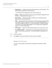
... assigned to queues 1, 2, 3 and 4 respectively. Enables configuring traffic scheduling on FE Devices, the default WRR Weight of 1, 2, 4 and 8 are assigned to the queue by the user. Indicates that traffic scheduling for the selected queue is selected on GE interfaces. The queues are displayed for classifying CoS settings to FE devices only. This field heading is updated. Displays the queue for which...
... assigned to queues 1, 2, 3 and 4 respectively. Enables configuring traffic scheduling on FE Devices, the default WRR Weight of 1, 2, 4 and 8 are assigned to the queue by the user. Indicates that traffic scheduling for the selected queue is selected on GE interfaces. The queues are displayed for classifying CoS settings to FE devices only. This field heading is updated. Displays the queue for which...
Administration Guide
Page 319
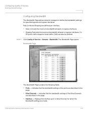
... Service Defining General Settings Configuring Bandwidth The Bandwidth Page allows network managers to define the bandwidth settings for specified egress and ingress interfaces. ESW 500 Series Switches Administration Guide 319 On GE ports, traffic shape for which the Bandwidth settings are described in the page. • Interface - Displays the interface (port or EtherChannel) for burst traffic (CbS) can also be defined. Indicates that the bandwidth settings of the EtherChannels are defined per interface: • Rate...
... Service Defining General Settings Configuring Bandwidth The Bandwidth Page allows network managers to define the bandwidth settings for specified egress and ingress interfaces. ESW 500 Series Switches Administration Guide 319 On GE ports, traffic shape for which the Bandwidth settings are described in the page. • Interface - Displays the interface (port or EtherChannel) for burst traffic (CbS) can also be defined. Indicates that the bandwidth settings of the EtherChannels are defined per interface: • Rate...
Administration Guide
Page 346
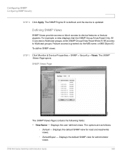
... opens: SNMP Views Page The SNMP Views Page contains the following fields: • View Name - To define SNMP views: STEP 1 Click Monitor & Device Properties > SNMP > Security > Views. The options are as follows: - For example, a view displays that the SNMP Group A has Read Only (R/ O) access to Multicast groups, while SNMP Group B has Read-Write (R/W) access to device features or feature aspects. DefaultSuper - Displays the default SNMP view for read and read/write views. - Displays the user-defined views. Default - ESW 500 Series Switches...
... opens: SNMP Views Page The SNMP Views Page contains the following fields: • View Name - To define SNMP views: STEP 1 Click Monitor & Device Properties > SNMP > Security > Views. The options are as follows: - For example, a view displays that the SNMP Group A has Read Only (R/ O) access to Multicast groups, while SNMP Group B has Read-Write (R/W) access to device features or feature aspects. DefaultSuper - Displays the default SNMP view for read and read/write views. - Displays the user-defined views. Default - ESW 500 Series Switches...
Administration Guide
Page 348
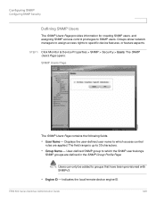
... Series Switches Administration Guide 348 The SNMP Users Page opens: SNMP Users Page The SNMP Users Page contains the following fields. • User Name - STEP 1 Click Monitor & Device Properties > SNMP > Security > Users. The field range is up to groups that have been provisioned with SNMPv3. • Engine ID - User-defined SNMP group to which the SNMP user belongs. NOTE Users can only be added to 30 characters. • Group Name - SNMP groups are applied. Configuring SNMP Configuring SNMP Security Defining SNMP Users The SNMP Users...
... Series Switches Administration Guide 348 The SNMP Users Page opens: SNMP Users Page The SNMP Users Page contains the following fields. • User Name - STEP 1 Click Monitor & Device Properties > SNMP > Security > Users. The field range is up to groups that have been provisioned with SNMPv3. • Engine ID - User-defined SNMP group to which the SNMP user belongs. NOTE Users can only be added to 30 characters. • Group Name - SNMP groups are applied. Configuring SNMP Configuring SNMP Security Defining SNMP Users The SNMP Users...
Administration Guide
Page 394
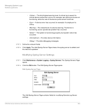
... Server Settings STEP 1 Click Maintenance > System Logging > Syslog Servers. A device error has occurred, for example, two device ports are not functioning, while the rest of a device warning. The device is functioning properly, but an operational problem has occurred. - Informational - The lowest level of the device ports remain functional. - Notice - Provides device information. - STEP 3 Define the relevant fields. The third highest warning level. Error - Managing System Logs Remote Log Servers - A critical log is updated...
... Server Settings STEP 1 Click Maintenance > System Logging > Syslog Servers. A device error has occurred, for example, two device ports are not functioning, while the rest of a device warning. The device is functioning properly, but an operational problem has occurred. - Informational - The lowest level of the device ports remain functional. - Notice - Provides device information. - STEP 3 Define the relevant fields. The third highest warning level. Error - Managing System Logs Remote Log Servers - A critical log is updated...

