
User Guide
Page 1
SRW224P ® A Division of Cisco Systems, Inc. 24-Port 10/100 + 2-Port Gigabit Switch with WebView and Power over Ethernet User Guide WIRED Model No.
SRW224P ® A Division of Cisco Systems, Inc. 24-Port 10/100 + 2-Port Gigabit Switch with WebView and Power over Ethernet User Guide WIRED Model No.
User Guide
Page 2
...addition to these symbols, there are trademarks or registered trademarks of interest and is a note of their respective holders. Copyright © 2005 Cisco Systems, Inc. All rights reserved. WARNING: This product contains chemicals, including lead, known to while using the Switch. Linksys is something you ...designed to make understanding networking with a reminder about something that are subject to cause cancer, and birth defects or other countries. SRW224P-UG-51008 KL This question mark provides you with the Switch easier than ever. and/or its affiliates in the "Table of...
...addition to these symbols, there are trademarks or registered trademarks of interest and is a note of their respective holders. Copyright © 2005 Cisco Systems, Inc. All rights reserved. WARNING: This product contains chemicals, including lead, known to while using the Switch. Linksys is something you ...designed to make understanding networking with a reminder about something that are subject to cause cancer, and birth defects or other countries. SRW224P-UG-51008 KL This question mark provides you with the Switch easier than ever. and/or its affiliates in the "Table of...
User Guide
Page 3
... the Console Interface 10 Overview 10 Configuring the Switch through the Console Interface 11 Chapter 5: Configuring the Switch through the Web Utility 24 Overview 24 System Information 25 IP Config 31 Switch Config 33 QoS 43 DiffServ 50 Security 56 SNTP 65 Statistics 66 PoE 68 Spanning Tree 71 SNMP 75...
... the Console Interface 10 Overview 10 Configuring the Switch through the Console Interface 11 Chapter 5: Configuring the Switch through the Web Utility 24 Overview 24 System Information 25 IP Config 31 Switch Config 33 QoS 43 DiffServ 50 Security 56 SNTP 65 Statistics 66 PoE 68 Spanning Tree 71 SNMP 75...

User Guide
Page 5
...Description 10 Figure 4-3: Password Screen 10 Figure 4-4: COM1 Properties 11 Figure 4-5: Login 11 Figure 4-6: Switch Main Menu 12 Figure 4-7: System Configuration Menu 12 Figure 4-8: System Information 13 Figure 4-9: Versions 13 Figure 4-10: General Information 13 Figure 4-11: Serial Port Configuration 14 Figure 4-12: CPU Performance ... 4-17: SNMP 17 Figure 4-18: Network Configuration/PING 17 Figure 4-19: File Management 18 Figure 4-20: Restore System Default Settings 19 Figure 4-21: Reboot System 19 Figure 4-22: Back to Main Menu 20 Figure 4-23: Port Status 21
...Description 10 Figure 4-3: Password Screen 10 Figure 4-4: COM1 Properties 11 Figure 4-5: Login 11 Figure 4-6: Switch Main Menu 12 Figure 4-7: System Configuration Menu 12 Figure 4-8: System Information 13 Figure 4-9: Versions 13 Figure 4-10: General Information 13 Figure 4-11: Serial Port Configuration 14 Figure 4-12: CPU Performance ... 4-17: SNMP 17 Figure 4-18: Network Configuration/PING 17 Figure 4-19: File Management 18 Figure 4-20: Restore System Default Settings 19 Figure 4-21: Reboot System 19 Figure 4-22: Back to Main Menu 20 Figure 4-23: Port Status 21

User Guide
Page 7
... 5-34: DiffServ Class Map - Setting Rules 54 Figure 5-38: DiffServ - Diffserv Service Policy 55 Figure 5-39: Security - Adding/Editing MAC ACL 59 Figure 5-43: Security - System Password 64 Figure 5-51: SNTP - Global Settings 65 Figure 5-52: Statistics - RMON Statistics 67 Figure 5-55: PoE - Power Port Config 69 Figure 5-57: PoE - Information...
... 5-34: DiffServ Class Map - Setting Rules 54 Figure 5-38: DiffServ - Diffserv Service Policy 55 Figure 5-39: Security - Adding/Editing MAC ACL 59 Figure 5-43: Security - System Password 64 Figure 5-51: SNTP - Global Settings 65 Figure 5-52: Statistics - RMON Statistics 67 Figure 5-55: PoE - Power Port Config 69 Figure 5-57: PoE - Information...

User Guide
Page 11
... that port. A green LED indicates a powered device is being supplied to the Switch. 24-Port 10/100 + 2-Port Gigabit Switch with an attached device. LEDs System Link/Act PoE Speed Figure 2-1: Front Panel A green LED indicates that power is connected to Know the Switch The Front Panel A green LED indicates a link...
... that port. A green LED indicates a powered device is being supplied to the Switch. 24-Port 10/100 + 2-Port Gigabit Switch with an attached device. LEDs System Link/Act PoE Speed Figure 2-1: Front Panel A green LED indicates that power is connected to Know the Switch The Front Panel A green LED indicates a link...

User Guide
Page 12
... Ethernet Ports LAN (1-24) The LAN ports connect to protect the Switch, is located on the back panel. They link to high-speed network peripheral system or clients at speeds of up to Know the Switch The Back Panel Figure 2-3: Side Panel 4 24-Port 10/100 + 2-Port Gigabit Switch with two...
... Ethernet Ports LAN (1-24) The LAN ports connect to protect the Switch, is located on the back panel. They link to high-speed network peripheral system or clients at speeds of up to Know the Switch The Back Panel Figure 2-3: Side Panel 4 24-Port 10/100 + 2-Port Gigabit Switch with two...

User Guide
Page 20
... to Main Menu. User and Password Settings 4. Chapter 4: Configuration using the Console Interface Configuring the Switch through the Console Interface Figure 4-6: Switch Main Menu Figure 4-7: System Configuration Menu 12 Management Settings 3. 24-Port 10/100 + 2-Port Gigabit Switch with Webview and Power over Ethernet Switch Main Menu The Main Menu screen...
... to Main Menu. User and Password Settings 4. Chapter 4: Configuration using the Console Interface Configuring the Switch through the Console Interface Figure 4-6: Switch Main Menu Figure 4-7: System Configuration Menu 12 Management Settings 3. 24-Port 10/100 + 2-Port Gigabit Switch with Webview and Power over Ethernet Switch Main Menu The Main Menu screen...
User Guide
Page 21
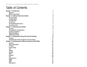
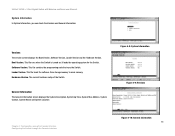
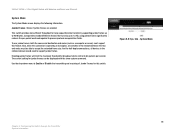
...from storage memory to main memory. General Information The General Information screen displays the System Description, System Up Time, System Mac Address, System Contact, System Name and System Location Figure 4-8: System Information Figure 4-9: Versions Chapter 4: Configuration using the Console Interface Configuring the Switch .../100 + 2-Port Gigabit Switch with Webview and Power over Ethernet System Information In System Information, you can check the Versions and General Information. It loads the operating system for the Switch. The current hardware setup of the Switch. This...
...from storage memory to main memory. General Information The General Information screen displays the System Description, System Up Time, System Mac Address, System Contact, System Name and System Location Figure 4-8: System Information Figure 4-9: Versions Chapter 4: Configuration using the Console Interface Configuring the Switch .../100 + 2-Port Gigabit Switch with Webview and Power over Ethernet System Information In System Information, you can check the Versions and General Information. It loads the operating system for the Switch. The current hardware setup of the Switch. This...

User Guide
Page 27
... To restore the Switch back to reboot the Switch, select Reboot System and press Enter. Figure 4-20: Restore System Default Settings Reboot System If you would like to the factory default settings, select Restore System Default Setting and press Enter. Figure 4-21: Reboot System 19 Chapter 4: Configuration using the Console Interface Configuring the Switch through...
... To restore the Switch back to reboot the Switch, select Reboot System and press Enter. Figure 4-20: Restore System Default Settings Reboot System If you would like to the factory default settings, select Restore System Default Setting and press Enter. Figure 4-21: Reboot System 19 Chapter 4: Configuration using the Console Interface Configuring the Switch through...

User Guide
Page 30
... 10/100 + 2-Port Gigabit Switch with Webview and Power over Ethernet PoE Configuration The PoE Main Menu screen displays three menu choices: System PoE Configuration, Port PoE Status and Port PoE Configuration. For example, when a device is automatically restored. Chapter 4: Configuration using the Console...the Switch through the Console Interface Figure 4-25: PoE Main Menu Figure 4-26: Power Configuration Figure 4-27: Power Port Status 22 System PoE Configuration The Power Configuration screen allows you to some low-priority ports and later the power demands on the Switch. When a...
... 10/100 + 2-Port Gigabit Switch with Webview and Power over Ethernet PoE Configuration The PoE Main Menu screen displays three menu choices: System PoE Configuration, Port PoE Status and Port PoE Configuration. For example, when a device is automatically restored. Chapter 4: Configuration using the Console...the Switch through the Console Interface Figure 4-25: PoE Main Menu Figure 4-26: Power Configuration Figure 4-27: Power Port Status 22 System PoE Configuration The Power Configuration screen allows you to some low-priority ports and later the power demands on the Switch. When a...

User Guide
Page 32
... will appear. The first time you configure and manage the Switch. Click the OK button. There are 14 tabs that appears displays the System Description screen for the Sys.Info tab. Figure 5-1: Address Field The first screen that run across the top of the screen: Sys.Info... Password Screen Chapter 5: Configuring the Switch through the Web Utility Overview Open your web browser and enter 192.168.1.254 into the address field. System Description 24 24-Port 10/100 + 2-Port Gigabit Switch with Webview and Power over Ethernet Chapter 5: Configuring the Switch through the Web Utility ...
... will appear. The first time you configure and manage the Switch. Click the OK button. There are 14 tabs that appears displays the System Description screen for the Sys.Info tab. Figure 5-1: Address Field The first screen that run across the top of the screen: Sys.Info... Password Screen Chapter 5: Configuring the Switch through the Web Utility Overview Open your web browser and enter 192.168.1.254 into the address field. System Description 24 24-Port 10/100 + 2-Port Gigabit Switch with Webview and Power over Ethernet Chapter 5: Configuring the Switch through the Web Utility ...

User Guide
Page 33
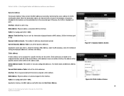
...The IP Address assigned to the following screens. • System Description • System Mode • Forwarding Database • Time Synchronization • CPU Performance • Logout System Description The System Description screen displays the following information. System Location. Assign a name to 255 characters long. 24...has been up to 255 characters long. Software version. The current hardware version is displayed. System name. Assign a name to the switch system, up to 255 characters long. Click the Submit button after you have verified that the ...
...The IP Address assigned to the following screens. • System Description • System Mode • Forwarding Database • Time Synchronization • CPU Performance • Logout System Description The System Description screen displays the following information. System Location. Assign a name to 255 characters long. 24...has been up to 255 characters long. Software version. The current hardware version is displayed. System name. Assign a name to the switch system, up to 255 characters long. Click the Submit button after you have verified that the ...
User Guide
Page 34
...threshold for broadcast storm control to 64 packets per -packet overhead required to process protocol encapsulation fields. System Mode 26 Chapter 5: Configuring the Switch through the Web Utility System Information To use jumbo frames, both the source and destination end nodes (such as a computer or... server) must be displayed with Webview and Power over Ethernet System Mode The System Mode screen displays the following information. The current setting for half-duplex connections, all switches in the collision domain would need...
...threshold for broadcast storm control to 64 packets per -packet overhead required to process protocol encapsulation fields. System Mode 26 Chapter 5: Configuring the Switch through the Web Utility System Information To use jumbo frames, both the source and destination end nodes (such as a computer or... server) must be displayed with Webview and Power over Ethernet System Mode The System Mode screen displays the following information. The current setting for half-duplex connections, all switches in the collision domain would need...

User Guide
Page 35
... changes. All the addresses learned by entering the number of time. Click Submit to a specific port. 27 Chapter 5: Configuring the Switch through the Web Utility System Information 24-Port 10/100 + 2-Port Gigabit Switch with Webview and Power over Ethernet Forwarding Database The Forwarding Database screen displays the following information. Forwarding...
... changes. All the addresses learned by entering the number of time. Click Submit to a specific port. 27 Chapter 5: Configuring the Switch through the Web Utility System Information 24-Port 10/100 + 2-Port Gigabit Switch with Webview and Power over Ethernet Forwarding Database The Forwarding Database screen displays the following information. Forwarding...
User Guide
Page 36
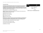
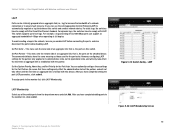
... to the address table. MAC Address. Physical address associated with the device assigned a static address. Interface. VLAN. Chapter 5: Configuring the Switch through the Web Utility System Information Figure 5-7: Dynamic Address Screen Figure 5-8: Static Address Screen 28 Otherwise, the traffic is flooded to all the static addresses. Dynamic Address Counts. Lists all...
... to the address table. MAC Address. Physical address associated with the device assigned a static address. Interface. VLAN. Chapter 5: Configuring the Switch through the Web Utility System Information Figure 5-7: Dynamic Address Screen Figure 5-8: Static Address Screen 28 Otherwise, the traffic is flooded to all the static addresses. Dynamic Address Counts. Lists all...
User Guide
Page 37
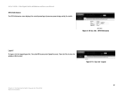
...it . Displays the current time. SNTP uses Coordinated Universal Time (or UTC, formerly Greenwich Mean Time, or GMT) based on the switch enables the system log to be specified in the configured sequence. Figure 5-9: Sys. Info - If the clock is east (after) or west (before) of UTC... server to record meaningful dates and times for the clock. Time Synchronization Screen 29 Chapter 5: Configuring the Switch through the Web Utility System Information Set the Direction by choosing the Before-UTC or After-UTC. Set the name, hours and minutes using the text fields. ...
...it . Displays the current time. SNTP uses Coordinated Universal Time (or UTC, formerly Greenwich Mean Time, or GMT) based on the switch enables the system log to be specified in the configured sequence. Figure 5-9: Sys. Info - If the clock is east (after) or west (before) of UTC... server to record meaningful dates and times for the clock. Time Synchronization Screen 29 Chapter 5: Configuring the Switch through the Web Utility System Information Set the Direction by choosing the Before-UTC or After-UTC. Set the name, hours and minutes using the text fields. ...
User Guide
Page 38
Figure 5-10: Sys. Info - Info - Then click OK to proceed or Cancel to cancel. Then click Yes to close the window or No to cancel. CPU Performance Logout To logout, click the Logout hyper-link. Logout 30 Chapter 5: Configuring the Switch through the Web Utility System Information Figure 5-11: Sys. 24-Port 10/100 + 2-Port Gigabit Switch with Webview and Power over Ethernet CPU Performance The CPU Performance screen displays the current percentage of processor power being used by the switch.
Figure 5-10: Sys. Info - Info - Then click OK to proceed or Cancel to cancel. Then click Yes to close the window or No to cancel. CPU Performance Logout To logout, click the Logout hyper-link. Logout 30 Chapter 5: Configuring the Switch through the Web Utility System Information Figure 5-11: Sys. 24-Port 10/100 + 2-Port Gigabit Switch with Webview and Power over Ethernet CPU Performance The CPU Performance screen displays the current percentage of processor power being used by the switch.

User Guide
Page 44
... information for each port. Tagging Information. Lists all VLANs, click the Show All radio button. VLAN type. This displays the amount of time since this system. Shows if this VLAN was created (that can be defined. Shows how this VLAN is enabled or disabled. Shows the tagging information for each VLAN..., but communicate as videoconferencing). 24-Port 10/100 + 2-Port Gigabit Switch with Webview and Power over Ethernet VLAN A VLAN is a group of ports that is, System Up Time).
... information for each port. Tagging Information. Lists all VLANs, click the Show All radio button. VLAN type. This displays the amount of time since this system. Shows if this VLAN was created (that can be defined. Shows how this VLAN is enabled or disabled. Shows the tagging information for each VLAN..., but communicate as videoconferencing). 24-Port 10/100 + 2-Port Gigabit Switch with Webview and Power over Ethernet VLAN A VLAN is a group of ports that is, System Up Time).
User Guide
Page 50
... to its administrative state, not its operational state, and will not take effect the next time an aggregate link is formed with the Cisco EtherChannel standard. However, configuring LACP settings for the Port Partner. (Be aware that these settings for the partner only applies to ensure fault... attributes have to automatically negotiate a lag link between this device.) After you can support an aggregate bandwidth of an aggregate link; Set the System Priority, Admin Key, and Port Priority for the port actor. For example, a lag consisting of two 1000 Mbps ports can use the Link...
... to its administrative state, not its operational state, and will not take effect the next time an aggregate link is formed with the Cisco EtherChannel standard. However, configuring LACP settings for the Port Partner. (Be aware that these settings for the partner only applies to ensure fault... attributes have to automatically negotiate a lag link between this device.) After you can support an aggregate bandwidth of an aggregate link; Set the System Priority, Admin Key, and Port Priority for the port actor. For example, a lag consisting of two 1000 Mbps ports can use the Link...