

Hardware Installation Guide
Page 24
... for the chassis grounding that is provided by the Telcordia specifications for central office use. Figure 1-1 Cisco uBR7111 and Cisco uBR7111E Universal Broadband Router-Rear Panel View 4 3 2 1 116834 5 I DS0 RF DS0 10 11 9 ACT ACT LNK FE 0/0 FE 0/1 1 SLOT 0 SLOT 1 US0 PWR CONS SYS AUX RDY EN uBR7114 7 8 6 5 1 ESD receptacle 2 Modular port adapter 3 Fixed Fast Ethernet...
... for the chassis grounding that is provided by the Telcordia specifications for central office use. Figure 1-1 Cisco uBR7111 and Cisco uBR7111E Universal Broadband Router-Rear Panel View 4 3 2 1 116834 5 I DS0 RF DS0 10 11 9 ACT ACT LNK FE 0/0 FE 0/1 1 SLOT 0 SLOT 1 US0 PWR CONS SYS AUX RDY EN uBR7114 7 8 6 5 1 ESD receptacle 2 Modular port adapter 3 Fixed Fast Ethernet...

Hardware Installation Guide
Page 28
...No No No No No No No No No Cisco uBR7100 Series and Cisco uBR7100E Series Universal Broadband Router Hardware Installation Guide 1-8 OL-5916-01 Table 1-1 lists and describes the port adapters supported by Cisco uBR7100 series routers. Field-Replaceable Units Figure 1-4 Port Adapter Locking ...Tabs Locked Unlocked Chapter 1 Product Overview 36092 5 I DS0 RF DS0 US3 ACT ACT LNK FE 0/0 FE 0/1 1 US2 SLOT 0 SLOT 1 US1 US0 PWR CONS SYS AUX RDY EN...
...No No No No No No No No No Cisco uBR7100 Series and Cisco uBR7100E Series Universal Broadband Router Hardware Installation Guide 1-8 OL-5916-01 Table 1-1 lists and describes the port adapters supported by Cisco uBR7100 series routers. Field-Replaceable Units Figure 1-4 Port Adapter Locking ...Tabs Locked Unlocked Chapter 1 Product Overview 36092 5 I DS0 RF DS0 US3 ACT ACT LNK FE 0/0 FE 0/1 1 US2 SLOT 0 SLOT 1 US1 US0 PWR CONS SYS AUX RDY EN...

Hardware Installation Guide
Page 33
... Numbering-Cisco uBR7100 Series PCMCIA Card slots (covered) Slot 3 Slot 0 Functional Overview 37634 5 I DS0 RF DS0 US3 ACT ACT LNK FE 0/0 FE 0/1 1 US2 SLOT 0 SLOT 1 US1 US0 PWR CONS SYS AUX RDY EN uBR7114 Slot 1 Note The slots for each interface is omitted: Router# show...specific interface, use the show interfaces command. The following example, most of the status information for each interface in a Cisco uBR7100 series router. In the following example shows how the show interfaces type slot/port. To display information about all interfaces, use the...
... Numbering-Cisco uBR7100 Series PCMCIA Card slots (covered) Slot 3 Slot 0 Functional Overview 37634 5 I DS0 RF DS0 US3 ACT ACT LNK FE 0/0 FE 0/1 1 US2 SLOT 0 SLOT 1 US1 US0 PWR CONS SYS AUX RDY EN uBR7114 Slot 1 Note The slots for each interface is omitted: Router# show...specific interface, use the show interfaces command. The following example, most of the status information for each interface in a Cisco uBR7100 series router. In the following example shows how the show interfaces type slot/port. To display information about all interfaces, use the...

Hardware Installation Guide
Page 39
... 1-7 Cisco uBR7111 System LEDS ACT ACT Active Active Link Link LNK LNK 21 PWR Power Sys Rdy SYS RDY 37403 5 I DS0 RF RF DS0 RF DS0 DS0 DS0 ACT ACT LNK FE 0/0 FE 0/1 1 SLOT 0 SLOT 1 US0 PWR CONS SYS AUX RDY EN uBR7114 EN Card Enable US0 U0 Enable Figure 1-8 Cisco uBR7114 ... SYS AUX RDY EN uBR7114 DS0 DS0 US3 U3 Enable US2 U2 Enable EN Card Enable US0 U0 Enable US1 U1 Enable OL-5916-01 Cisco uBR7100 Series and Cisco uBR7100E Series Universal Broadband Router Hardware Installation Guide 1-19 Caution To prevent system errors and problems, use the CPU reset ...
... 1-7 Cisco uBR7111 System LEDS ACT ACT Active Active Link Link LNK LNK 21 PWR Power Sys Rdy SYS RDY 37403 5 I DS0 RF RF DS0 RF DS0 DS0 DS0 ACT ACT LNK FE 0/0 FE 0/1 1 SLOT 0 SLOT 1 US0 PWR CONS SYS AUX RDY EN uBR7114 EN Card Enable US0 U0 Enable Figure 1-8 Cisco uBR7114 ... SYS AUX RDY EN uBR7114 DS0 DS0 US3 U3 Enable US2 U2 Enable EN Card Enable US0 U0 Enable US1 U1 Enable OL-5916-01 Cisco uBR7100 Series and Cisco uBR7100E Series Universal Broadband Router Hardware Installation Guide 1-19 Caution To prevent system errors and problems, use the CPU reset ...

Hardware Installation Guide
Page 40
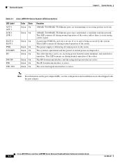
... accessed by the system. The PCMCIA card slot (0 or 1) is in use and is active. 1-20 Cisco uBR7100 Series and Cisco uBR7100E Series Universal Broadband Router Hardware Installation Guide OL-5916-01 The RF downstream interface and the integrated upconverter are transmitting or receiving packets (...an incoming carrier signal. Functional Overview Chapter 1 Product Overview Table 1-5 Cisco uBR7100 Series System LED Descriptions LED Label ACT 0 ACT 1 LNK 0 LNK 1 SLOT 0 SLOT 1 PWR SYS RDY EN DS0 RF DS0 US0-US3 Color State Green On Function 10BASE-T/100BASE-TX Ethernet ports are active...
... accessed by the system. The PCMCIA card slot (0 or 1) is in use and is active. 1-20 Cisco uBR7100 Series and Cisco uBR7100E Series Universal Broadband Router Hardware Installation Guide OL-5916-01 The RF downstream interface and the integrated upconverter are transmitting or receiving packets (...an incoming carrier signal. Functional Overview Chapter 1 Product Overview Table 1-5 Cisco uBR7100 Series System LED Descriptions LED Label ACT 0 ACT 1 LNK 0 LNK 1 SLOT 0 SLOT 1 PWR SYS RDY EN DS0 RF DS0 US0-US3 Color State Green On Function 10BASE-T/100BASE-TX Ethernet ports are active...

Hardware Installation Guide
Page 61
...and Cisco uBR7100E Series Universal Broadband Router Hardware Installation Guide 3-7 Figure 3-8 Attaching the Cable-Management Bracket to the Chassis (Cisco uBR7114 chassis) Chassis grounding receptacles Screws 35825 5 I DS0 RF DS0 US3 ACT ACT LNK FE 0/0 FE 0/1 1 US2 SLOT 0 SLOT 1 US1 US0 PWR... of the grounding wire to the appropriate grounding point at your site to the Cisco uBR7114 or Cisco uBR7114E chassis; Attach the cable-management bracket to the two grounding receptacles that the two flanges on page 3-5. the Cisco uBR7111 or Cisco uBR7111E chassis is identical.
...and Cisco uBR7100E Series Universal Broadband Router Hardware Installation Guide 3-7 Figure 3-8 Attaching the Cable-Management Bracket to the Chassis (Cisco uBR7114 chassis) Chassis grounding receptacles Screws 35825 5 I DS0 RF DS0 US3 ACT ACT LNK FE 0/0 FE 0/1 1 US2 SLOT 0 SLOT 1 US1 US0 PWR... of the grounding wire to the appropriate grounding point at your site to the Cisco uBR7114 or Cisco uBR7114E chassis; Attach the cable-management bracket to the two grounding receptacles that the two flanges on page 3-5. the Cisco uBR7111 or Cisco uBR7111E chassis is identical.

Hardware Installation Guide
Page 62
... DS0 RF DS0 US3 DS0 RF DS0 US3 ACT ACT LNK FE 0/0 FE 0/1 1 US2 SLOT 0 SLOT 1 US1 US0 PWR CONS SYS AUX RDY EN uBR7114 US2 US1 US0 Upstream ports Downstream port (to your port adapter. When detaching cables, detach the end away from the unit first. Use ... adapter separately as follows: • DS0 RF outputs the downstream after it has been processed by the Cisco uBR7100 series integrated upconverter. The cables required to connect the router to the unit is not recommended for both the upstream and downstream ports. Statement 1001 Warning Hazardous network ...
... DS0 RF DS0 US3 DS0 RF DS0 US3 ACT ACT LNK FE 0/0 FE 0/1 1 US2 SLOT 0 SLOT 1 US1 US0 PWR CONS SYS AUX RDY EN uBR7114 US2 US1 US0 Upstream ports Downstream port (to your port adapter. When detaching cables, detach the end away from the unit first. Use ... adapter separately as follows: • DS0 RF outputs the downstream after it has been processed by the Cisco uBR7100 series integrated upconverter. The cables required to connect the router to the unit is not recommended for both the upstream and downstream ports. Statement 1001 Warning Hazardous network ...

Hardware Installation Guide
Page 63
...PC or other Ethernet device. • Use Category 5 UTP straight-through Ethernet cable OL-5916-01 Cisco uBR7100 Series and Cisco uBR7100E Series Universal Broadband Router Hardware Installation Guide 3-9 Each Fast Ethernet port has an RJ-45 connector that the Ethernet hub is ...35826 5 I DS0 RF DS0 US3 ACT ACT LNK FE 0/0 FE 0/1 1 US2 SLOT 0 SLOT 1 US1 US0 PWR CONS SYS AUX RDY EN uBR7114 10BASE-T/100BASE-TX ports Fast Ethernet 0/0 (RJ-45) Cisco uBR7100 series router Ethernet hub 8 7 6 5 4 3 2 1 Straight-through cables when connecting 100BASE-TX to a hub....
...PC or other Ethernet device. • Use Category 5 UTP straight-through Ethernet cable OL-5916-01 Cisco uBR7100 Series and Cisco uBR7100E Series Universal Broadband Router Hardware Installation Guide 3-9 Each Fast Ethernet port has an RJ-45 connector that the Ethernet hub is ...35826 5 I DS0 RF DS0 US3 ACT ACT LNK FE 0/0 FE 0/1 1 US2 SLOT 0 SLOT 1 US1 US0 PWR CONS SYS AUX RDY EN uBR7114 10BASE-T/100BASE-TX ports Fast Ethernet 0/0 (RJ-45) Cisco uBR7100 series router Ethernet hub 8 7 6 5 4 3 2 1 Straight-through cables when connecting 100BASE-TX to a hub....

Hardware Installation Guide
Page 64
....) Figure 3-11 Connecting the Console Terminal 35827 5 I DS0 RF DS0 US3 ACT ACT LNK FE 0/0 FE 0/1 1 US2 SLOT 0 SLOT 1 US1 US0 PWR CONS SYS AUX RDY EN uBR7114 Console port (RJ-45) Cisco uBR7100 series router PC (laptop) RJ-45-to-RJ-45 rollover cable RJ-45-to-DB-9 adapter (labeled TERMINAL) 3-10...
....) Figure 3-11 Connecting the Console Terminal 35827 5 I DS0 RF DS0 US3 ACT ACT LNK FE 0/0 FE 0/1 1 US2 SLOT 0 SLOT 1 US1 US0 PWR CONS SYS AUX RDY EN uBR7114 Console port (RJ-45) Cisco uBR7100 series router PC (laptop) RJ-45-to-RJ-45 rollover cable RJ-45-to-DB-9 adapter (labeled TERMINAL) 3-10...

Hardware Installation Guide
Page 65
... are typical). Configure the modem for auto-answer, and for either hardware or software flow control. OL-5916-01 Cisco uBR7100 Series and Cisco uBR7100E Series Universal Broadband Router Hardware Installation Guide 3-11 Connecting a Modem to the Auxiliary Port You can use the following procedure: Step 1 Connect... to the auxiliary port on the router. (See Figure 3-12.) Figure 3-12 Connecting a Modem to the Auxiliary Port 35828 5 I DS0 RF DS0 US3 RJ-45-to-RJ-45 rollover cable ACT ACT LNK FE 0/0 FE 0/1 1 US2 SLOT 0 SLOT 1 US1 US0 PWR CONS SYS AUX RDY EN...
... are typical). Configure the modem for auto-answer, and for either hardware or software flow control. OL-5916-01 Cisco uBR7100 Series and Cisco uBR7100E Series Universal Broadband Router Hardware Installation Guide 3-11 Connecting a Modem to the Auxiliary Port You can use the following procedure: Step 1 Connect... to the auxiliary port on the router. (See Figure 3-12.) Figure 3-12 Connecting a Modem to the Auxiliary Port 35828 5 I DS0 RF DS0 US3 RJ-45-to-RJ-45 rollover cable ACT ACT LNK FE 0/0 FE 0/1 1 US2 SLOT 0 SLOT 1 US1 US0 PWR CONS SYS AUX RDY EN...

Hardware Installation Guide
Page 66
... DS0 RF DS0 US3 ACT ACT LNK FE 0/0 FE 0/1 1 US2 SLOT 0 SLOT 1 US1 US0 PWR CONS SYS AUX RDY EN uBR7114 Note For information on the back of the router. (See Figure 3-13.) Connect the other end of the power cord to the power connector on ... on the power supply specifications, see Chapter 4, "System Startup." 3-12 Cisco uBR7100 Series and Cisco uBR7100E Series Universal Broadband Router Hardware Installation Guide OL-5916-01 Cisco uBR7100 series routers have one end of the router, check that provide power factor correction and regulated outputs. Warning Do not touch...
... DS0 RF DS0 US3 ACT ACT LNK FE 0/0 FE 0/1 1 US2 SLOT 0 SLOT 1 US1 US0 PWR CONS SYS AUX RDY EN uBR7114 Note For information on the back of the router. (See Figure 3-13.) Connect the other end of the power cord to the power connector on ... on the power supply specifications, see Chapter 4, "System Startup." 3-12 Cisco uBR7100 Series and Cisco uBR7100E Series Universal Broadband Router Hardware Installation Guide OL-5916-01 Cisco uBR7100 series routers have one end of the router, check that provide power factor correction and regulated outputs. Warning Do not touch...

Hardware Installation Guide
Page 69
...The LEDs indicate the status of the interface LEDs do not go on until you to check the status of your service representative. Figure 4-1 Cisco uBR7111 System LEDS ACT ACT Active Active Link Link LNK LNK 21 PWR Power Sys Rdy SYS RDY 37403 5 I DS0 RF RF DS0 RF ... CONS SYS AUX RDY EN uBR7114 DS0 DS0 US3 U3 Enable US2 U2 Enable EN Card Enable US0 U0 Enable US1 U1 Enable OL-5916-01 Cisco uBR7100 Series and Cisco uBR7100E Series Universal Broadband Router Hardware Installation Guide 4-3 The CPU reset button that you have configured them. Chapter 4 System Startup ...
...The LEDs indicate the status of the interface LEDs do not go on until you to check the status of your service representative. Figure 4-1 Cisco uBR7111 System LEDS ACT ACT Active Active Link Link LNK LNK 21 PWR Power Sys Rdy SYS RDY 37403 5 I DS0 RF RF DS0 RF ... CONS SYS AUX RDY EN uBR7114 DS0 DS0 US3 U3 Enable US2 U2 Enable EN Card Enable US0 U0 Enable US1 U1 Enable OL-5916-01 Cisco uBR7100 Series and Cisco uBR7100E Series Universal Broadband Router Hardware Installation Guide 4-3 The CPU reset button that you have configured them. Chapter 4 System Startup ...
Hardware Installation Guide
Page 70
... Series and Cisco uBR7100E Series Universal Broadband Router Hardware Installation Guide 4-4 OL-5916-01 Starting the System Chapter 4 System Startup Table 4-1 Cisco uBR7100 Series System LED Descriptions LED Label ACT 0 ACT 1 LNK 0 LNK 1 SLOT 0 SLOT 1 PWR SYS RDY EN DS0 RF DS0 US0-US3 Color State Green On Function 10BASE-T/100BASE-TX Ethernet ports...
... Series and Cisco uBR7100E Series Universal Broadband Router Hardware Installation Guide 4-4 OL-5916-01 Starting the System Chapter 4 System Startup Table 4-1 Cisco uBR7100 Series System LED Descriptions LED Label ACT 0 ACT 1 LNK 0 LNK 1 SLOT 0 SLOT 1 PWR SYS RDY EN DS0 RF DS0 US0-US3 Color State Green On Function 10BASE-T/100BASE-TX Ethernet ports...
Hardware Installation Guide
Page 72
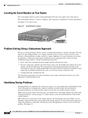
...sections help you isolate a problem to the appropriate troubleshooting section. Cisco uBR7100 Series and Cisco uBR7100E Series Universal Broadband Router Hardware Installation Guide 5-2 OL-5916-01 Troubleshooting Overview Chapter 5 ...Troubleshooting the Installation Locating the Serial Number on Your Router The serial number label is located on the input/output (I DS0 RF DS0 US3 ACT ACT LNK FE 0/0 FE 0/1 1 US2 SLOT 0 SLOT 1 US1 US0...
...sections help you isolate a problem to the appropriate troubleshooting section. Cisco uBR7100 Series and Cisco uBR7100E Series Universal Broadband Router Hardware Installation Guide 5-2 OL-5916-01 Troubleshooting Overview Chapter 5 ...Troubleshooting the Installation Locating the Serial Number on Your Router The serial number label is located on the input/output (I DS0 RF DS0 US3 ACT ACT LNK FE 0/0 FE 0/1 1 US2 SLOT 0 SLOT 1 US1 US0...
Hardware Installation Guide
Page 82
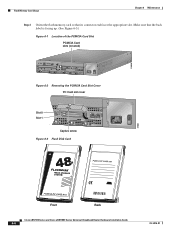
... Card Slot PCMCIA Card slots (covered) 116836 5 I DS0 RF DS0 US3 ACT ACT LNK FE 0/0 FE 0/1 1 US2 SLOT 0 SLOT 1 US1 US0 PWR CONS SYS AUX RDY EN uBR7114 Figure 6-2 Removing the PCMCIA Card Slot Cover PC Card slot cover Slot 0 Slot 1 ACT ACT LNK FE 0/0 ...FE 0/1 1 US2 SLOT 0 SLOT 1 US1 US0 Captive screw Figure 6-3 Flash Disk Card PWR CONS SYS AUX RDY EN uBR7114 37638 37853 Front Back Cisco uBR7100 Series and Cisco uBR7100E Series Universal Broadband Router Hardware Installation Guide 6-6 OL-5916-01 Make sure that its connector end ...
... Card Slot PCMCIA Card slots (covered) 116836 5 I DS0 RF DS0 US3 ACT ACT LNK FE 0/0 FE 0/1 1 US2 SLOT 0 SLOT 1 US1 US0 PWR CONS SYS AUX RDY EN uBR7114 Figure 6-2 Removing the PCMCIA Card Slot Cover PC Card slot cover Slot 0 Slot 1 ACT ACT LNK FE 0/0 ...FE 0/1 1 US2 SLOT 0 SLOT 1 US1 US0 Captive screw Figure 6-3 Flash Disk Card PWR CONS SYS AUX RDY EN uBR7114 37638 37853 Front Back Cisco uBR7100 Series and Cisco uBR7100E Series Universal Broadband Router Hardware Installation Guide 6-6 OL-5916-01 Make sure that its connector end ...