

Hardware Installation Guide
Page 3
... a Service Request 18 Definitions of Service Request Severity 19 Obtaining Additional Publications and Information 19 Product Overview 1 Product Description 1 Cisco uBR7100 Series Models 2 Cisco uBR7111 and Cisco uBR7111E 2 Cisco uBR7114 and Cisco uBR7114E 2 Cisco uBR7100 Series Router Operational Features 2 Cisco uBR7100 Series Routers Physical Description 3 Fixed Interface Units 6 Ethernet/Fast Ethernet LAN Interface 6 RF Cable Interface 6 Field-Replaceable Units 7 Port Adapters...
... a Service Request 18 Definitions of Service Request Severity 19 Obtaining Additional Publications and Information 19 Product Overview 1 Product Description 1 Cisco uBR7100 Series Models 2 Cisco uBR7111 and Cisco uBR7111E 2 Cisco uBR7114 and Cisco uBR7114E 2 Cisco uBR7100 Series Router Operational Features 2 Cisco uBR7100 Series Routers Physical Description 3 Fixed Interface Units 6 Ethernet/Fast Ethernet LAN Interface 6 RF Cable Interface 6 Field-Replaceable Units 7 Port Adapters...

Hardware Installation Guide
Page 7
... this equipment. You should be allowed to all models of the Cisco uBR7100 series universal broadband router, including the Cisco uBR7111, Cisco uBR7111E, Cisco uBR7114, and Cisco uBR7114E routers. Purpose This installation guide explains the initial hardware installation and basic configuration procedures for installing the router hardware, starting up the router, and troubleshooting any problems that might occur during the installation...
... this equipment. You should be allowed to all models of the Cisco uBR7100 series universal broadband router, including the Cisco uBR7111, Cisco uBR7111E, Cisco uBR7114, and Cisco uBR7114E routers. Purpose This installation guide explains the initial hardware installation and basic configuration procedures for installing the router hardware, starting up the router, and troubleshooting any problems that might occur during the installation...

Hardware Installation Guide
Page 21
..., page 1-12 Note Unless otherwise indicated, the term Cisco uBR7100 series in the 5 to all models of the Cisco uBR7100 series universal broadband router, including the Cisco uBR7111, Cisco uBR7111E, Cisco uBR7114, and Cisco uBR7114E routers. OL-5916-01 Cisco uBR7100 Series and Cisco uBR7100E Series Universal Broadband Router Hardware Installation Guide 1-1 The Cisco uBR7100 series routers support two-way data and digitized voice connectivity...
..., page 1-12 Note Unless otherwise indicated, the term Cisco uBR7100 series in the 5 to all models of the Cisco uBR7100 series universal broadband router, including the Cisco uBR7111, Cisco uBR7111E, Cisco uBR7114, and Cisco uBR7114E routers. OL-5916-01 Cisco uBR7100 Series and Cisco uBR7100E Series Universal Broadband Router Hardware Installation Guide 1-1 The Cisco uBR7100 series routers support two-way data and digitized voice connectivity...

Hardware Installation Guide
Page 22
...-5916-01 The Cisco uBR7114 router supports DOCSIS cable plants, and the Cisco uBR7114E supports EuroDOCSIS cable plants. The Cisco uBR7111 router supports DOCSIS cable plants, and the Cisco uBR7111E supports EuroDOCSIS cable plants. The router contains a combination of operation. • Front to back airflow-Internal fans provide all necessary cooling. Cisco uBR7111 and Cisco uBR7111E The Cisco uBR7111 and Cisco uBR7111E universal broadband routers provide the following...
...-5916-01 The Cisco uBR7114 router supports DOCSIS cable plants, and the Cisco uBR7114E supports EuroDOCSIS cable plants. The Cisco uBR7111 router supports DOCSIS cable plants, and the Cisco uBR7111E supports EuroDOCSIS cable plants. The router contains a combination of operation. • Front to back airflow-Internal fans provide all necessary cooling. Cisco uBR7111 and Cisco uBR7111E The Cisco uBR7111 and Cisco uBR7111E universal broadband routers provide the following...

Hardware Installation Guide
Page 24
... AC power supply outlet. Figure 1-2 shows the rear panel of the Cisco uBR7111 and Cisco uBR7111E routers. Cisco uBR7100 Series and Cisco uBR7100E Series Universal Broadband Router Hardware Installation Guide 1-4 OL-5916-01 Figure 1-1 Cisco uBR7111 and Cisco uBR7111E Universal Broadband Router-Rear Panel View 4 3 2 1 116834 5 I DS0 RF DS0...grounding receptacles are shown in Figure 1-1 and Figure 1-2 are located at the back of the router. Cisco uBR7100 Series Routers Physical Description Chapter 1 Product Overview All interface connections and LEDs are for the chassis grounding ...
... AC power supply outlet. Figure 1-2 shows the rear panel of the Cisco uBR7111 and Cisco uBR7111E routers. Cisco uBR7100 Series and Cisco uBR7100E Series Universal Broadband Router Hardware Installation Guide 1-4 OL-5916-01 Figure 1-1 Cisco uBR7111 and Cisco uBR7111E Universal Broadband Router-Rear Panel View 4 3 2 1 116834 5 I DS0 RF DS0...grounding receptacles are shown in Figure 1-1 and Figure 1-2 are located at the back of the router. Cisco uBR7100 Series Routers Physical Description Chapter 1 Product Overview All interface connections and LEDs are for the chassis grounding ...

Hardware Installation Guide
Page 26
...downstream port and from one to 42 MHz upstream frequency range. Cisco uBR7100 Series and Cisco uBR7100E Series Universal Broadband Router Hardware Installation Guide 1-6 OL-5916-01 Note On the Cisco uBR7111E and Cisco uBR7114E routers, the DS0 connector is automatically muted when the DS0 RF port...100BASE-TX Fast Ethernet network. Each port uses an RJ-45 connector with two separately routable 100BASE-TX ports. On the Cisco uBR7111 and Cisco uBR7114 routers, the cable interface supports the North American DOCSIS channel plan, with a 6 MHz National Television Systems Committee (NTSC) ...
...downstream port and from one to 42 MHz upstream frequency range. Cisco uBR7100 Series and Cisco uBR7100E Series Universal Broadband Router Hardware Installation Guide 1-6 OL-5916-01 Note On the Cisco uBR7111E and Cisco uBR7114E routers, the DS0 connector is automatically muted when the DS0 RF port...100BASE-TX Fast Ethernet network. Each port uses an RJ-45 connector with two separately routable 100BASE-TX ports. On the Cisco uBR7111 and Cisco uBR7114 routers, the cable interface supports the North American DOCSIS channel plan, with a 6 MHz National Television Systems Committee (NTSC) ...

Hardware Installation Guide
Page 27
... and Cable-Management Kit, page 1-12 Port Adapters The Cisco uBR7100 series routers support a wide range of port adapters. Supported port adapters include: Ethernet, Fast Ethernet, Synchronous Serial, HSSI, ATM, and SONET interfaces, see Figure 1-4). The Cisco uBR7111 and Cisco uBR7111E routers support one time. Refer to the router and are locked into position by a locking tab and...
... and Cable-Management Kit, page 1-12 Port Adapters The Cisco uBR7100 series routers support a wide range of port adapters. Supported port adapters include: Ethernet, Fast Ethernet, Synchronous Serial, HSSI, ATM, and SONET interfaces, see Figure 1-4). The Cisco uBR7111 and Cisco uBR7111E routers support one time. Refer to the router and are locked into position by a locking tab and...
Hardware Installation Guide
Page 32
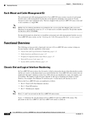
... the type of modular port adapter or fixed interface. Functional Overview The following sections provide a functional overview of Cisco uBR7100 series routers to install the rack-mount and cable-management brackets on the Cisco uBR7111 and Cisco uBR7111E routers is available separately. The kit is shipped with the capabilities of rack-mount brackets and a cable-management bracket...
... the type of modular port adapter or fixed interface. Functional Overview The following sections provide a functional overview of Cisco uBR7100 series routers to install the rack-mount and cable-management brackets on the Cisco uBR7111 and Cisco uBR7111E routers is available separately. The kit is shipped with the capabilities of rack-mount brackets and a cable-management bracket...

Hardware Installation Guide
Page 39
...To prevent system errors and problems, use the CPU reset button only at the direction of the router. The LEDs are shown in Figure 1-7 and Figure 1-8, and are described in Table 1-5. Figure 1-7 Cisco uBR7111 System LEDS ACT ACT Active Active Link Link LNK LNK 21 PWR Power Sys Rdy SYS RDY ...DS0 DS0 US3 U3 Enable US2 U2 Enable EN Card Enable US0 U0 Enable US1 U1 Enable OL-5916-01 Cisco uBR7100 Series and Cisco uBR7100E Series Universal Broadband Router Hardware Installation Guide 1-19 Chapter 1 Product Overview Functional Overview System LEDs and Reset Button The LEDs indicate the ...
...To prevent system errors and problems, use the CPU reset button only at the direction of the router. The LEDs are shown in Figure 1-7 and Figure 1-8, and are described in Table 1-5. Figure 1-7 Cisco uBR7111 System LEDS ACT ACT Active Active Link Link LNK LNK 21 PWR Power Sys Rdy SYS RDY ...DS0 DS0 US3 U3 Enable US2 U2 Enable EN Card Enable US0 U0 Enable US1 U1 Enable OL-5916-01 Cisco uBR7100 Series and Cisco uBR7100E Series Universal Broadband Router Hardware Installation Guide 1-19 Chapter 1 Product Overview Functional Overview System LEDs and Reset Button The LEDs indicate the ...

Hardware Installation Guide
Page 61
.... Figure 3-8 shows how to attach the cable-management brackets to the vacant receptacles. the Cisco uBR7111 or Cisco uBR7111E chassis is identical. Chapter 3 Installing Cisco uBR7100 Series Universal Broadband Routers Attaching the Cable-Management Bracket Step 7 Connect the opposite end of Cisco uBR7100 series chassis have two grounding receptacles. Ensure that were not used to the Chassis...
.... Figure 3-8 shows how to attach the cable-management brackets to the vacant receptacles. the Cisco uBR7111 or Cisco uBR7111E chassis is identical. Chapter 3 Installing Cisco uBR7100 Series Universal Broadband Routers Attaching the Cable-Management Bracket Step 7 Connect the opposite end of Cisco uBR7100 series chassis have two grounding receptacles. Ensure that were not used to the Chassis...

Hardware Installation Guide
Page 69
... operation of each interface, complete the first-time startup procedures and configuration, and then use the CPU reset button only at the direction of the router. Figure 4-1 Cisco uBR7111 System LEDS ACT ACT Active Active Link Link LNK LNK 21 PWR Power Sys Rdy SYS RDY 37403 5 I DS0 RF RF DS0 RF DS0... SYS AUX RDY EN uBR7114 DS0 DS0 US3 U3 Enable US2 U2 Enable EN Card Enable US0 U0 Enable US1 U1 Enable OL-5916-01 Cisco uBR7100 Series and Cisco uBR7100E Series Universal Broadband Router Hardware Installation Guide 4-3
... operation of each interface, complete the first-time startup procedures and configuration, and then use the CPU reset button only at the direction of the router. Figure 4-1 Cisco uBR7111 System LEDS ACT ACT Active Active Link Link LNK LNK 21 PWR Power Sys Rdy SYS RDY 37403 5 I DS0 RF RF DS0 RF DS0... SYS AUX RDY EN uBR7114 DS0 DS0 US3 U3 Enable US2 U2 Enable EN Card Enable US0 U0 Enable US1 U1 Enable OL-5916-01 Cisco uBR7100 Series and Cisco uBR7100E Series Universal Broadband Router Hardware Installation Guide 4-3

Hardware Installation Guide
Page 96
...page 1-8. CISP22:1997 Class B; CNS13438:1997 Class B EN61000-3-2:1995; Refer to +38 dBmV 1. Table A-2 Cisco uBR7100 Series Cable Interface Specifications Router Model Downstream Modulation Upstream Modulation IF Output1 uBR7111 64 QAM QPSK +35 to +43 dBmV uBR7114 64 QAM QPSK +35 to +43 dBmV... uBR7111E 64 QAM QPSK +33 to +38 dBmV uBR7114E 64 QAM QPSK +33 to Regulatory Compliance and Safety Information for the Cisco uBR7100 and Cisco uBR7100E Series Universal Broadband Routers for EuroDOCSIS operations Compliance marking CE, CSA, ...
...page 1-8. CISP22:1997 Class B; CNS13438:1997 Class B EN61000-3-2:1995; Refer to +38 dBmV 1. Table A-2 Cisco uBR7100 Series Cable Interface Specifications Router Model Downstream Modulation Upstream Modulation IF Output1 uBR7111 64 QAM QPSK +35 to +43 dBmV uBR7114 64 QAM QPSK +35 to +43 dBmV... uBR7111E 64 QAM QPSK +33 to +38 dBmV uBR7114E 64 QAM QPSK +33 to Regulatory Compliance and Safety Information for the Cisco uBR7100 and Cisco uBR7100E Series Universal Broadband Routers for EuroDOCSIS operations Compliance marking CE, CSA, ...

Hardware Installation Guide
Page 101
.... 5. These settings are baseline settings for cable system variations over time and temperature. OL-5916-01 Cisco uBR7100 Series and Cisco uBR7100E Series Universal Broadband Router Hardware Installation Guide A-7 Minimum settings are slightly different than the EuroDOCSIS settings to adjacent video signal -6 ...must be put through an external upconverter before use. Note The integrated upconverter output is enabled. Note On the Cisco uBR7111E and Cisco uBR7114E routers, the DS0 connector is automatically muted when the DS0 RF port is available on the downstream port labeled DS0...
.... 5. These settings are baseline settings for cable system variations over time and temperature. OL-5916-01 Cisco uBR7100 Series and Cisco uBR7100E Series Universal Broadband Router Hardware Installation Guide A-7 Minimum settings are slightly different than the EuroDOCSIS settings to adjacent video signal -6 ...must be put through an external upconverter before use. Note The integrated upconverter output is enabled. Note On the Cisco uBR7111E and Cisco uBR7114E routers, the DS0 connector is automatically muted when the DS0 RF port is available on the downstream port labeled DS0...