
Hardware Installation Guide
Page 19
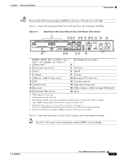
...in a 1905 or 1921. 5. Figure 1-3 shows the front panel of a Cisco 1941 wireless router with ports and LEDs. OL-19084-02 Cisco 1900 Series Hardware Installation 1-3 Figure 1-2 shows the back panel of the Cisco 1905 and Cisco 1921 Router (1921 shown) 1 EHWIC 1 FLASH 18 EHWIC 0 234 5 6... console) and 1-slot 0 (Right), slot 1 (Left), or 1 double wide2345 2 3 RJ-45 serial console port 4 AUX port 5 GE 0/1 7 S (Speed) 9 USB port-USB 2.0 Type-A port 11 PoE6 13 On/Off switch 6 GE 0/0 8 L (Link) 10 KensingtonTM security slot 12 Ground connector 14 Input power connection 15 Baud reset 17...
...in a 1905 or 1921. 5. Figure 1-3 shows the front panel of a Cisco 1941 wireless router with ports and LEDs. OL-19084-02 Cisco 1900 Series Hardware Installation 1-3 Figure 1-2 shows the back panel of the Cisco 1905 and Cisco 1921 Router (1921 shown) 1 EHWIC 1 FLASH 18 EHWIC 0 234 5 6... console) and 1-slot 0 (Right), slot 1 (Left), or 1 double wide2345 2 3 RJ-45 serial console port 4 AUX port 5 GE 0/1 7 S (Speed) 9 USB port-USB 2.0 Type-A port 11 PoE6 13 On/Off switch 6 GE 0/0 8 L (Link) 10 KensingtonTM security slot 12 Ground connector 14 Input power connection 15 Baud reset 17...

Hardware Installation Guide
Page 21
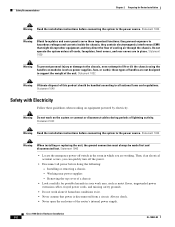
...19 20 21 22 EHWIC 1 DO NOT REMOVE DURING NETWORKING OPERATION CF 1 Cisco 1900 Series EHWIC 0 DO NOT REMOVE DURING CF 0 ISM/WLAN EN NETWORKING OPERATION AUX S L G E 0 / 0 EN CONSOLE GE 0/1 S L 1 USB 0 273452 16 15 14 13 12 11 10 9 8 7 6 5 4 3 2 1 USB ports-two USB 2.0 Type-A ports 1 (USB 0=Bottom) L (Link) 2 3 GE 0/1 4 S (... 13 HWIC slot 1 (EHWIC, HWIC, or WIC)-double wide4 15 CompactFlash 1 14 CF 1 16 KensingtonTM security slot 17 On/Off switch 18 Input power connection 19 AUX port 20 S (Speed) 21 GE 0/0 22 L (Link) 1. Internal Service Module (ISM). 4.
...19 20 21 22 EHWIC 1 DO NOT REMOVE DURING NETWORKING OPERATION CF 1 Cisco 1900 Series EHWIC 0 DO NOT REMOVE DURING CF 0 ISM/WLAN EN NETWORKING OPERATION AUX S L G E 0 / 0 EN CONSOLE GE 0/1 S L 1 USB 0 273452 16 15 14 13 12 11 10 9 8 7 6 5 4 3 2 1 USB ports-two USB 2.0 Type-A ports 1 (USB 0=Bottom) L (Link) 2 3 GE 0/1 4 S (... 13 HWIC slot 1 (EHWIC, HWIC, or WIC)-double wide4 15 CompactFlash 1 14 CF 1 16 KensingtonTM security slot 17 On/Off switch 18 Input power connection 19 AUX port 20 S (Speed) 21 GE 0/0 22 L (Link) 1. Internal Service Module (ISM). 4.

Hardware Installation Guide
Page 24
... One console port (RJ-45 connector). In addition to optional integrated switch modules. You will be prompted to install the driver. The Cisco 1905, and Cisco 1921 have a USB 5-pin mini Type-B port. The chassis cover should never be installed. Table 1-2 summarizes the optional modules: Cisco 1900 Series Hardware ...the internal power supply providing in-line power (802.3af-compliant Power-over-Ethernet (PoE) and Cisco standard inline power) to the RJ-45 Console port, the Cisco 1900 ISRs have an external feed for USB devices such as security tokens and flash memory. Table 1-1...
... One console port (RJ-45 connector). In addition to optional integrated switch modules. You will be prompted to install the driver. The Cisco 1905, and Cisco 1921 have a USB 5-pin mini Type-B port. The chassis cover should never be installed. Table 1-2 summarizes the optional modules: Cisco 1900 Series Hardware ...the internal power supply providing in-line power (802.3af-compliant Power-over-Ethernet (PoE) and Cisco standard inline power) to the RJ-45 Console port, the Cisco 1900 ISRs have an external feed for USB devices such as security tokens and flash memory. Table 1-1...
Hardware Installation Guide
Page 36
...connect or disconnect cables during periods of cooling air through the chassis. Removing the top cover of the router's internal power supply. Cisco 1900 Series Hardware Installation 2-2 OL-19084-02 Safety Recommendations Chapter 2 Preparing for possible hazards in place. Statement 1029 Warning To prevent ... the following: - Statement 1032 Warning Ultimate disposal of the unit. Then, if an electrical accident occurs, you can quickly turn off switch in the room in which you are in your work area, such as power supplies, fans, or cards); these guidelines when working...
...connect or disconnect cables during periods of cooling air through the chassis. Removing the top cover of the router's internal power supply. Cisco 1900 Series Hardware Installation 2-2 OL-19084-02 Safety Recommendations Chapter 2 Preparing for possible hazards in place. Statement 1029 Warning To prevent ... the following: - Statement 1032 Warning Ultimate disposal of the unit. Then, if an electrical accident occurs, you can quickly turn off switch in the room in which you are in your work area, such as power supplies, fans, or cards); these guidelines when working...

Hardware Installation Guide
Page 48
... Routers • Synchronous interface-Maximum baud rate is located on Cisco.com. Cisco 1900 Series Hardware Installation 3-6 OL-19084-01 Table 3-3 ISDN BRI Cable Specifications Specification Resistance (at 96 kHz) Capacitance (at 1 kHz) Impedance... Network Termination 1 (NT1), or a U interface that provide switched 56-kbps connections, or full or fractionalized T1 connections. To avoid electric shock, use caution when working near WAN ports. For more information on BRI WICs, refer to Cisco.com. Statement 23 Warning Hazardous network voltages are available that has...
... Routers • Synchronous interface-Maximum baud rate is located on Cisco.com. Cisco 1900 Series Hardware Installation 3-6 OL-19084-01 Table 3-3 ISDN BRI Cable Specifications Specification Resistance (at 96 kHz) Capacitance (at 1 kHz) Impedance... Network Termination 1 (NT1), or a U interface that provide switched 56-kbps connections, or full or fractionalized T1 connections. To avoid electric shock, use caution when working near WAN ports. For more information on BRI WICs, refer to Cisco.com. Statement 23 Warning Hazardous network voltages are available that has...

Hardware Installation Guide
Page 61
... Cable Gigabit Ethernet (GE) RJ-45, yellow Ethernet switch or hub. Table 4-1 WAN and LAN Connections Port or Connection Port Type, Color1 Connected to a PBX or any other equipment) Cisco serial (1T) Cisco Smart serial (2T) 60-pin D-sub, blue Cisco Smart compact connector, blue CSU/DSU and serial network ...NT1 device or PINX3 RJ-45 straight-through for device for Cisco 1900 series routers. Cisco serial transition cable that matches the signaling protocol (EIA/TIA-232, EIA/TIA-449, V.35, X.21, or EIA/TIA-530) and the serial port operating mode (DTE or DCE). RJ-14 straight-through . ...
... Cable Gigabit Ethernet (GE) RJ-45, yellow Ethernet switch or hub. Table 4-1 WAN and LAN Connections Port or Connection Port Type, Color1 Connected to a PBX or any other equipment) Cisco serial (1T) Cisco Smart serial (2T) 60-pin D-sub, blue Cisco Smart compact connector, blue CSU/DSU and serial network ...NT1 device or PINX3 RJ-45 straight-through for device for Cisco 1900 series routers. Cisco serial transition cable that matches the signaling protocol (EIA/TIA-232, EIA/TIA-449, V.35, X.21, or EIA/TIA-530) and the serial port operating mode (DTE or DCE). RJ-14 straight-through . ...

Hardware Installation Guide
Page 71
... screws from the DC circuit. Tighten the terminal screws to the OFF position, and tape the circuit-breaker switch in -lb (0.9 ± 0.05 N-m). OL-19084-02 Cisco 1900 Series Hardware Installation 4-23 Warning When stranded wiring is removed from the DC circuit, locate the circuit breaker... for the DC circuit, switch the circuit breaker to 8.0 ± 0.5 in the OFF position. Chapter 4 Installing and Connecting the Router Connecting Power Cisco 1900 Series Router Wiring Procedure for the wires and should clamp both the insulation and...
... screws from the DC circuit. Tighten the terminal screws to the OFF position, and tape the circuit-breaker switch in -lb (0.9 ± 0.05 N-m). OL-19084-02 Cisco 1900 Series Hardware Installation 4-23 Warning When stranded wiring is removed from the DC circuit, locate the circuit breaker... for the DC circuit, switch the circuit breaker to 8.0 ± 0.5 in the OFF position. Chapter 4 Installing and Connecting the Router Connecting Power Cisco 1900 Series Router Wiring Procedure for the wires and should clamp both the insulation and...
Hardware Installation Guide
Page 73
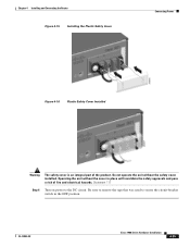
.... Statement 117 Step 6 Turn on power to secure the circuit-breaker switch in place will invalidate the safety approvals and pose a risk of the product. Do not operate the unit without the cover in the OFF position. OL-19084-02 Cisco 1900 Series Hardware Installation 4-25 Chapter 4 Installing and Connecting the Router Figure...
.... Statement 117 Step 6 Turn on power to secure the circuit-breaker switch in place will invalidate the safety approvals and pose a risk of the product. Do not operate the unit without the cover in the OFF position. OL-19084-02 Cisco 1900 Series Hardware Installation 4-25 Chapter 4 Installing and Connecting the Router Figure...

Hardware Installation Guide
Page 76
... see Changing the Configuration Register Settings. Procedure Step 1 Move the power switch to verify the router has performed the initialization and self-test. Cisco 1900 Series Hardware Installation 5-2 OL-19084-02 Powering Up the Cisco Router To power up your Cisco router, follow this time are interpreted as described in the "Checklist Before... 5 Configuring the Router • You have a PC with a terminal emulation program (HyperTerminal or equivalent) that your PC is ready to the console port. It takes a few minutes for the Ethernet and serial interfaces.
... see Changing the Configuration Register Settings. Procedure Step 1 Move the power switch to verify the router has performed the initialization and self-test. Cisco 1900 Series Hardware Installation 5-2 OL-19084-02 Powering Up the Cisco Router To power up your Cisco router, follow this time are interpreted as described in the "Checklist Before... 5 Configuring the Router • You have a PC with a terminal emulation program (HyperTerminal or equivalent) that your PC is ready to the console port. It takes a few minutes for the Ethernet and serial interfaces.


