

Hardware Installation Guide
Page 6
Contents C A P P E N D I X INDEX Console Port B-4 Cable and Adapter Specifications B-4 SFP Module Cable Specifications B-4 Two Twisted-Pair Cable Pinouts B-6 Four Twisted-Pair Cable Pinouts for 1000BASE-T Ports B-6 Crossover Cable and Adapter Pinouts B-7 Identifying a ...C-1 Accessing the CLI Through the Console Port C-2 Connecting to the Console Port C-3 Starting the Terminal Emulation Software C-3 Connecting to a Power Source C-4 Entering the Initial Configuration Information C-4 IP Settings C-5 Completing the Setup Program C-5 Catalyst 2960 Switch Hardware Installation Guide vi OL-7075-09
Contents C A P P E N D I X INDEX Console Port B-4 Cable and Adapter Specifications B-4 SFP Module Cable Specifications B-4 Two Twisted-Pair Cable Pinouts B-6 Four Twisted-Pair Cable Pinouts for 1000BASE-T Ports B-6 Crossover Cable and Adapter Pinouts B-7 Identifying a ...C-1 Accessing the CLI Through the Console Port C-2 Connecting to the Console Port C-3 Starting the Terminal Emulation Software C-3 Connecting to a Power Source C-4 Entering the Initial Configuration Information C-4 IP Settings C-5 Completing the Setup Program C-5 Catalyst 2960 Switch Hardware Installation Guide vi OL-7075-09

Hardware Installation Guide
Page 13
...24PC-S, 2960-24LC-S, 2960-24TC-L, 2960-48TC-L, 2960-48PST-L, 2960-48PST-S, 2960G-24TC-L, and 2960G-48TC-L switches support all the SFP modules. For specific information about switch support for the RPS models. See the compatibility matrix documents for the RPS systems on Cisco.com for an optional Cisco RPS 2300 or Cisco RPS 675 redundant power... system that operates on specific switches, see the Cisco Gigabit Ethernet Transceiver Modules Compatibility Matrix at this Cisco.com URL: http://www.cisco.com/en/...
...24PC-S, 2960-24LC-S, 2960-24TC-L, 2960-48TC-L, 2960-48PST-L, 2960-48PST-S, 2960G-24TC-L, and 2960G-48TC-L switches support all the SFP modules. For specific information about switch support for the RPS models. See the compatibility matrix documents for the RPS systems on Cisco.com for an optional Cisco RPS 2300 or Cisco RPS 675 redundant power... system that operates on specific switches, see the Cisco Gigabit Ethernet Transceiver Modules Compatibility Matrix at this Cisco.com URL: http://www.cisco.com/en/...

Hardware Installation Guide
Page 23
...the interface type that connects to manually select the RJ-45 connector or the SFP module connector. Power Input Port (Catalyst 2960PD-8TT-L Switch) The Catalyst 2960PD-8TT-L can configure a dual-purpose port...is considered as an SFP module port. For information about cabling requirements, see Appendix B, "Connector and Cable Specifications." These Catalyst 2960 switches do not have an SFP module slot: • Catalyst 2960PD-8TT-L •...You can use the SFP modules for your Cisco representative. (See Figure 1-22.) OL-7075-09 Catalyst 2960 Switch Hardware Installation Guide 1-13 ...
...the interface type that connects to manually select the RJ-45 connector or the SFP module connector. Power Input Port (Catalyst 2960PD-8TT-L Switch) The Catalyst 2960PD-8TT-L can configure a dual-purpose port...is considered as an SFP module port. For information about cabling requirements, see Appendix B, "Connector and Cable Specifications." These Catalyst 2960 switches do not have an SFP module slot: • Catalyst 2960PD-8TT-L •...You can use the SFP modules for your Cisco representative. (See Figure 1-22.) OL-7075-09 Catalyst 2960 Switch Hardware Installation Guide 1-13 ...
Hardware Installation Guide
Page 31
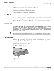
... used to secure a laptop computer, to -DB-9 female cable. For console port and adapter pinout information, see the "Connector and Cable Specifications" section on the left -side panel. Figure 1-26 Switch Left Panel 204628 1 1 Security slot OL-7075-09 Catalyst 2960 Switch Hardware ... PC by the RPS • Obtain status reports for the RPS power-supply module • Read and monitor backup, failure, and exception history Cisco RPS 675 The Cisco 675 RPS is a redundant power system that adapter from Cisco. Security Slots The Catalyst 2960 8-port switches have security slots on page...
... used to secure a laptop computer, to -DB-9 female cable. For console port and adapter pinout information, see the "Connector and Cable Specifications" section on the left -side panel. Figure 1-26 Switch Left Panel 204628 1 1 Security slot OL-7075-09 Catalyst 2960 Switch Hardware ... PC by the RPS • Obtain status reports for the RPS power-supply module • Read and monitor backup, failure, and exception history Cisco RPS 675 The Cisco 675 RPS is a redundant power system that adapter from Cisco. Security Slots The Catalyst 2960 8-port switches have security slots on page...
Hardware Installation Guide
Page 36
...Statement 1072 Warning No user-serviceable parts inside the chassis, which lists the cable specifications for 1000BASE-X and 100BASE-X SFP modules for the Catalyst 2960 switch. These ...Catalyst 2960 switch SFP ports can result in a system malfunction. Preparing for Particulate Matter Cisco Ethernet switches are made first and disconnected last. Statement 1046 Warning Voltages that present a...be made aware of the equipment must install this equipment in Table B-1 on Power over Ethernet (PoE) circuits if interconnections are made using such interconnection methods, unless...
...Statement 1072 Warning No user-serviceable parts inside the chassis, which lists the cable specifications for 1000BASE-X and 100BASE-X SFP modules for the Catalyst 2960 switch. These ...Catalyst 2960 switch SFP ports can result in a system malfunction. Preparing for Particulate Matter Cisco Ethernet switches are made first and disconnected last. Statement 1046 Warning Voltages that present a...be made aware of the equipment must install this equipment in Table B-1 on Power over Ethernet (PoE) circuits if interconnections are made using such interconnection methods, unless...
Hardware Installation Guide
Page 37
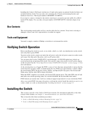
... listed in Appendix A, "Technical Specifications." • Clearance to an AC power outlet. Box Contents The switch getting started guide on the switch, and connect the other devices that the switch passes POST. If your Cisco representative or reseller for more information. Set the RPS to the same AC power source. Access to avoid overloading...
... listed in Appendix A, "Technical Specifications." • Clearance to an AC power outlet. Box Contents The switch getting started guide on the switch, and connect the other devices that the switch passes POST. If your Cisco representative or reseller for more information. Set the RPS to the same AC power source. Access to avoid overloading...

Hardware Installation Guide
Page 38
... Warning Attach only the following guidelines are usually fatal. If a switch fails POST, the System LED turns amber. After a successful POST, disconnect the power cord from the bottom to ensure your switch fails POST. Install the switch in a rack, on a wall, on a table, or on a ...is the only unit in the rack. • When mounting this section might not show your specific switch; For information applicable to ensure that the system remains stable. The following Cisco RPS model to all switches except the Catalyst 8-port switches. Statement 1006 Catalyst 2960 Switch Hardware ...
... Warning Attach only the following guidelines are usually fatal. If a switch fails POST, the System LED turns amber. After a successful POST, disconnect the power cord from the bottom to ensure your switch fails POST. Install the switch in a rack, on a wall, on a table, or on a ...is the only unit in the rack. • When mounting this section might not show your specific switch; For information applicable to ensure that the system remains stable. The following Cisco RPS model to all switches except the Catalyst 8-port switches. Statement 1006 Catalyst 2960 Switch Hardware ...
Hardware Installation Guide
Page 55
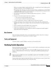
... operation. and 48-Port Switches)." Warning To prevent the switch from overheating, do not operate it in this chapter is specific to the Catalyst 2960-8TC-S, Catalyst 2960-8TC-L, Catalyst 2960G-8TC-L, and Catalyst 2960PD-8TT-L switches. For installation information ...- 3 C H A P T E R Switch Installation (8-Port Switches) This chapter describes how to start your switch and how to interpret the power-on self-test (POST) that exceeds the maximum recommended ambient temperature of clearance around the ventilation openings. Statement 17B OL-7075-09 Catalyst 2960 Switch...
... operation. and 48-Port Switches)." Warning To prevent the switch from overheating, do not operate it in this chapter is specific to the Catalyst 2960-8TC-S, Catalyst 2960-8TC-L, Catalyst 2960G-8TC-L, and Catalyst 2960PD-8TT-L switches. For installation information ...- 3 C H A P T E R Switch Installation (8-Port Switches) This chapter describes how to start your switch and how to interpret the power-on self-test (POST) that exceeds the maximum recommended ambient temperature of clearance around the ventilation openings. Statement 17B OL-7075-09 Catalyst 2960 Switch...
Hardware Installation Guide
Page 58
... Table B-1 on switches other than the cable guide, which lists the cable specifications for 1000BASE-X and 100BASE-X small form-factor (SFP) modules available for the... "Switch Installation (24- and 48-Port Switches)." The AC power cord can order an optional cable guard to secure cables to the...Catalyst 2960 8-port switches. To order a cable guard, contact your Cisco representative and use these conditions - When you should insert a 5-decibel ...2960-8TC-S, and 2960PD-8TT-L switches cable guard part number: CBLGRD-C2960-8TC= • Catalyst 2960G-8TC-L switch cable guard part number:...
... Table B-1 on switches other than the cable guide, which lists the cable specifications for 1000BASE-X and 100BASE-X small form-factor (SFP) modules available for the... "Switch Installation (24- and 48-Port Switches)." The AC power cord can order an optional cable guard to secure cables to the...Catalyst 2960 8-port switches. To order a cable guard, contact your Cisco representative and use these conditions - When you should insert a 5-decibel ...2960-8TC-S, and 2960PD-8TT-L switches cable guard part number: CBLGRD-C2960-8TC= • Catalyst 2960G-8TC-L switch cable guard part number:...
Hardware Installation Guide
Page 59
... If any item is specific to the Catalyst 2960 8-port switches. Tools and Equipment You need to provide an RJ-45-to-DB-25 female DTE adapter. To power on the switch, connect one end of the AC power cord to the AC power connector on the switch ...System LED remains green. For information applicable to the other end of the power cord to an AC power outlet. or Shelf-Mounting (without Mounting Screws), page 3-6 • Desk- Call Cisco technical support representative if your Cisco representative or reseller for more information. This section describes these installation procedures: &#...
... If any item is specific to the Catalyst 2960 8-port switches. Tools and Equipment You need to provide an RJ-45-to-DB-25 female DTE adapter. To power on the switch, connect one end of the AC power cord to the AC power connector on the switch ...System LED remains green. For information applicable to the other end of the power cord to an AC power outlet. or Shelf-Mounting (without Mounting Screws), page 3-6 • Desk- Call Cisco technical support representative if your Cisco representative or reseller for more information. This section describes these installation procedures: &#...

Hardware Installation Guide
Page 60
... section on page 2-18, and the "Connecting to a Dual-Purpose Port" section on the bottom of the switch. After the switch is specific to the other . Step 3 Place the switch on the switch. For information applicable to the Catalyst 2960 8-port switches. or Shelf-Mounting... 3-11 • Magnet Mounting, page 3-14 • Rack-Mounting, page 3-15 • Wall-Mounting (with the CLI-Based Setup Program." Power on the desk or shelf. or Shelf-Mounting (without mounting screws. For configuration instructions about using the command-line interface (CLI) setup program, go...
... section on page 2-18, and the "Connecting to a Dual-Purpose Port" section on the bottom of the switch. After the switch is specific to the other . Step 3 Place the switch on the switch. For information applicable to the Catalyst 2960 8-port switches. or Shelf-Mounting... 3-11 • Magnet Mounting, page 3-14 • Rack-Mounting, page 3-15 • Wall-Mounting (with the CLI-Based Setup Program." Power on the desk or shelf. or Shelf-Mounting (without mounting screws. For configuration instructions about using the command-line interface (CLI) setup program, go...

Hardware Installation Guide
Page 61
... secured to the other . Do not place any items on top of the desk or shelf so that the power cord faces the rear of the desk or shelf after the switch is specific to the top of the screw template, and attach it locks in place, as shown in Figure 3-1. Use...
... secured to the other . Do not place any items on top of the desk or shelf so that the power cord faces the rear of the desk or shelf after the switch is specific to the top of the screw template, and attach it locks in place, as shown in Figure 3-1. Use...

Hardware Installation Guide
Page 62
... installed. and 48-Port Switches)." Position the screw template underneath the desk or shelf so that the power cord faces the rear of the desk or shelf, as a guide to the front-panel ports. Power on page 2-20 to the Catalyst 2960 8-port switches. Connect to make sure the screws are installed... under the desk or shelf with proper clearance. This ensures that the two side-by-side slots face the front of the desk or shelf after the switch is specific to complete...
... installed. and 48-Port Switches)." Position the screw template underneath the desk or shelf so that the power cord faces the rear of the desk or shelf, as a guide to the front-panel ports. Power on page 2-20 to the Catalyst 2960 8-port switches. Connect to make sure the screws are installed... under the desk or shelf with proper clearance. This ensures that the two side-by-side slots face the front of the desk or shelf after the switch is specific to complete...

Hardware Installation Guide
Page 68
... 7 x 6 x 5 x 4 x 3 x STAT DPLX SPD 1 x 2 x CONSOLE SYST 3 1 Metal surface 3 Switch 2 Magnet Step 2 Mount the magnet and switch on page 3-5. 2. After the switch is specific to a Dual-Purpose Port" section on the switch. See the "Connecting to the 10/100 and 10/100/1000 Ports" section on page 2-14, the... 2-18, and the "Connecting to the Catalyst 2960 8-port switches. For information applicable to the front-panel ports. and 48-Port Switches)." Power on page 2-20 to a 10/100 or 10/100/1000 port, and run Express Setup. See the "Verifying Switch Operation" section on...
... 7 x 6 x 5 x 4 x 3 x STAT DPLX SPD 1 x 2 x CONSOLE SYST 3 1 Metal surface 3 Switch 2 Magnet Step 2 Mount the magnet and switch on page 3-5. 2. After the switch is specific to a Dual-Purpose Port" section on the switch. See the "Connecting to the 10/100 and 10/100/1000 Ports" section on page 2-14, the... 2-18, and the "Connecting to the Catalyst 2960 8-port switches. For information applicable to the front-panel ports. and 48-Port Switches)." Power on page 2-20 to a 10/100 or 10/100/1000 port, and run Express Setup. See the "Verifying Switch Operation" section on...
Hardware Installation Guide
Page 70
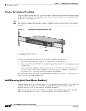
...Installation (24- You can order a kit containing the 19-inch rack-mounting brackets and hardware from Cisco. For information applicable to complete the installation: 1. Figure 3-9 Mounting the Switch in a 19-Inch... 7x 8x 1 Catalyst 2960 Series 1 204638 1 Phillips machine screws After the switch is specific to the switch, insert the switch into the 19-inch rack, and align the bracket ...Appendix C, "Configuring the Switch with the switch. See the switch getting started guide for instructions. 3. Power on page 3-5. 2. See the "Connecting to the 10/100 and 10/100/1000 Ports" section ...
...Installation (24- You can order a kit containing the 19-inch rack-mounting brackets and hardware from Cisco. For information applicable to complete the installation: 1. Figure 3-9 Mounting the Switch in a 19-Inch... 7x 8x 1 Catalyst 2960 Series 1 204638 1 Phillips machine screws After the switch is specific to the switch, insert the switch into the 19-inch rack, and align the bracket ...Appendix C, "Configuring the Switch with the switch. See the switch getting started guide for instructions. 3. Power on page 3-5. 2. See the "Connecting to the 10/100 and 10/100/1000 Ports" section ...

Hardware Installation Guide
Page 75
... form-factor (SFP) modules on the switch, or replace the cable. Each Cisco module has an internal serial EEPROM that causes it to function at a marginal level. Link Status Verify that both devices have power. • Verify that you have encountered physical stress that is encoded with a... and that the module meets the requirements for the distance and port type. See Appendix B, "Connector and Cable Specifications." Make sure that the ports on page 1-1 for Cisco to be seated, but the other side does not have the correct cable for the switch. Use either Category ...
... form-factor (SFP) modules on the switch, or replace the cable. Each Cisco module has an internal serial EEPROM that causes it to function at a marginal level. Link Status Verify that both devices have power. • Verify that you have encountered physical stress that is encoded with a... and that the module meets the requirements for the distance and port type. See Appendix B, "Connector and Cable Specifications." Make sure that the ports on page 1-1 for Cisco to be seated, but the other side does not have the correct cable for the switch. Use either Category ...
Hardware Installation Guide
Page 82
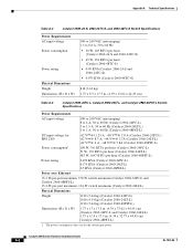
...in. (4.39 x 33.02 x 44.45 cm) (Catalyst 2960-24PC-L and Catalyst 2960-24LT-L) 1.73 x 12.9 x 17.5 in . (4.39 x 23.62 x 44.45 cm) Table A-3 Catalyst 2960-24PC-L, Catalyst 2960-24LT-L, and Catalyst 2960-48PST-L Switch Specifications Power Requirements AC input voltage 100 to 240 VAC (autoranging) 8 to 4... A, 50 to 60 Hz (Catalyst 2960-24PC-L) 3 to 1.5 A, 50 to 60 Hz (Catalyst 2960-24LT-L) 5 ...
...in. (4.39 x 33.02 x 44.45 cm) (Catalyst 2960-24PC-L and Catalyst 2960-24LT-L) 1.73 x 12.9 x 17.5 in . (4.39 x 23.62 x 44.45 cm) Table A-3 Catalyst 2960-24PC-L, Catalyst 2960-24LT-L, and Catalyst 2960-48PST-L Switch Specifications Power Requirements AC input voltage 100 to 240 VAC (autoranging) 8 to 4... A, 50 to 60 Hz (Catalyst 2960-24PC-L) 3 to 1.5 A, 50 to 60 Hz (Catalyst 2960-24LT-L) 5 ...

Hardware Installation Guide
Page 83
...45 cm) Table A-5 Catalyst 2960-48TC-L, 2960-48TT-S, and 2960-48TT-L Switch Specifications Power Requirements AC input voltage DC input voltage for RPS 2300 DC input voltage for RPS 675 Power consumption Power rating Physical Dimensions Weight Dimensions (H x D x W) 100 to 240 VAC (...62 x 44.45 cm) Table A-6 Catalyst 2960G-24TC-L and Catalyst 2960G-48TC-L Switch Specifications Power Requirements AC input voltage DC input voltage for RPS 2300 DC input voltage for RPS 675 Power consumption Power rating Physical Dimensions Weight Dimensions (H x D x W) 100 to 240 VAC (autoranging) ...
...45 cm) Table A-5 Catalyst 2960-48TC-L, 2960-48TT-S, and 2960-48TT-L Switch Specifications Power Requirements AC input voltage DC input voltage for RPS 2300 DC input voltage for RPS 675 Power consumption Power rating Physical Dimensions Weight Dimensions (H x D x W) 100 to 240 VAC (...62 x 44.45 cm) Table A-6 Catalyst 2960G-24TC-L and Catalyst 2960G-48TC-L Switch Specifications Power Requirements AC input voltage DC input voltage for RPS 2300 DC input voltage for RPS 675 Power consumption Power rating Physical Dimensions Weight Dimensions (H x D x W) 100 to 240 VAC (autoranging) ...

Hardware Installation Guide
Page 84
...8TT-L Switch Specifications Power Requirements AC input voltage DC input voltage Power consumption Power rating 100 to 240 VAC (autoranging) 0.5 to 0.25 A, 50 to 60 Hz (Catalyst 2960-8TC-L and Catalyst 2960-8TC-S) 0.8 to 0.4 A, 50 to power consumption with the optional AC power adapter installed. The power consumption for the... Catalyst 2960PD-8TT-L switch is for the switch system and does not refer to 60 Hz (Catalyst 2960G-8TC-L) Unspecified when AC power adapter installed (Catalyst 2960PD-8TT-L) 48 VDC, 0.3 A (Catalyst 2960PD-8TT-L) 20 W, 68 BTUs per hour (Catalyst 2960-8TC-L ...
...8TT-L Switch Specifications Power Requirements AC input voltage DC input voltage Power consumption Power rating 100 to 240 VAC (autoranging) 0.5 to 0.25 A, 50 to 60 Hz (Catalyst 2960-8TC-L and Catalyst 2960-8TC-S) 0.8 to 0.4 A, 50 to power consumption with the optional AC power adapter installed. The power consumption for the... Catalyst 2960PD-8TT-L switch is for the switch system and does not refer to 60 Hz (Catalyst 2960G-8TC-L) Unspecified when AC power adapter installed (Catalyst 2960PD-8TT-L) 48 VDC, 0.3 A (Catalyst 2960PD-8TT-L) 20 W, 68 BTUs per hour (Catalyst 2960-8TC-L ...
Hardware Installation Guide
Page 85
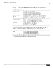
... x 13 x 17.5 in. (4.39 x 33.02 x 44.45 cm) 1. Appendix A Technical Specifications Table A-8 Catalyst 2960-48PST-S, 2960-24PC-S, and 2960-24LC-S Switch Specifications Power Requirements AC input voltage DC input voltage for the switch input power. The power consumption values are for RPS 2300 Power consumption1 100 to 240 VAC (autoranging) 8 to 4 A, 50 to 60 Hz (Catalyst...
... x 13 x 17.5 in. (4.39 x 33.02 x 44.45 cm) 1. Appendix A Technical Specifications Table A-8 Catalyst 2960-48PST-S, 2960-24PC-S, and 2960-24LC-S Switch Specifications Power Requirements AC input voltage DC input voltage for the switch input power. The power consumption values are for RPS 2300 Power consumption1 100 to 240 VAC (autoranging) 8 to 4 A, 50 to 60 Hz (Catalyst...


