Hardware Installation Guide
Page 3
...1-6 Catalyst 2960G-24TC-L and Catalyst 2960G-48TC-L Switches 1-8 Catalyst 2960 8-Port Switches 1-9 Catalyst 2960PD-8TT-L Switch 1-9 Catalyst 2960-8TC-S, Catalyst 2960-8TC-L, and Catalyst 2960G-8TC -L Switches 1-10 10/100 Ports 1-11 10/100/1000 Ports 1-11 PoE Ports (Only Catalyst 2960 PoE Switches) 1-12 SFP ... 1-18 Cable Guard for the Catalyst 2960 8-Port Switches 1-19 Rear Panel Description 1-19 Internal Power Supply 1-20 Cisco RPS 1-20 Cisco RPS 2300 1-20 Cisco RPS 675 1-21 Console Port 1-21 Security Slots 1-21 Management Options 1-22 Network Configurations 1-22 Catalyst 2960 Switch Hardware...
...1-6 Catalyst 2960G-24TC-L and Catalyst 2960G-48TC-L Switches 1-8 Catalyst 2960 8-Port Switches 1-9 Catalyst 2960PD-8TT-L Switch 1-9 Catalyst 2960-8TC-S, Catalyst 2960-8TC-L, and Catalyst 2960G-8TC -L Switches 1-10 10/100 Ports 1-11 10/100/1000 Ports 1-11 PoE Ports (Only Catalyst 2960 PoE Switches) 1-12 SFP ... 1-18 Cable Guard for the Catalyst 2960 8-Port Switches 1-19 Rear Panel Description 1-19 Internal Power Supply 1-20 Cisco RPS 1-20 Cisco RPS 2300 1-20 Cisco RPS 675 1-21 Console Port 1-21 Security Slots 1-21 Management Options 1-22 Network Configurations 1-22 Catalyst 2960 Switch Hardware...
Hardware Installation Guide
Page 7
...guide, the switch command reference, and the switch system message guide on the Cisco Training & Events web page: http://www.cisco.com/web/learning/index.html Purpose This guide describes the hardware features of Ethernet and local area networking. In this manual. OL-7075-09 ... familiar with the concepts and terminology of the Catalyst 2960 switch. If you might do something that you are available on the Cisco.com Product Documentation home page. Caution Means reader be careful. Conventions This document uses these areas, learning opportunities including training courses,...
...guide, the switch command reference, and the switch system message guide on the Cisco Training & Events web page: http://www.cisco.com/web/learning/index.html Purpose This guide describes the hardware features of Ethernet and local area networking. In this manual. OL-7075-09 ... familiar with the concepts and terminology of the Catalyst 2960 switch. If you might do something that you are available on the Cisco.com Product Documentation home page. Caution Means reader be careful. Conventions This document uses these areas, learning opportunities including training courses,...

Hardware Installation Guide
Page 11
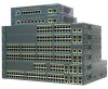
...switch. Table 1-1 describes the switch model features. The Catalyst 2960 8-port compact switches provide the same Ethernet connectivity, but you can connect devices such as workstations, Cisco Wireless Access Points, Cisco IP Phones, and other network devices including... servers, routers, and other network devices. Product Overview 1 C H A P T E R The Catalyst 2960 switch-also referred to as the switch-is an Ethernet switch to which you can deploy the 24- Table 1-1 Catalyst 2960 Switch Model Descriptions Switch Model Catalyst 2960-8TC...
...switch. Table 1-1 describes the switch model features. The Catalyst 2960 8-port compact switches provide the same Ethernet connectivity, but you can connect devices such as workstations, Cisco Wireless Access Points, Cisco IP Phones, and other network devices including... servers, routers, and other network devices. Product Overview 1 C H A P T E R The Catalyst 2960 switch-also referred to as the switch-is an Ethernet switch to which you can deploy the 24- Table 1-1 Catalyst 2960 Switch Model Descriptions Switch Model Catalyst 2960-8TC...
Hardware Installation Guide
Page 12
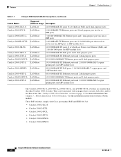
Features Chapter 1 Product Overview Table 1-1 Catalyst 2960 Switch Model Descriptions (continued) Switch Model Catalyst 2960-24LC-S Catalyst 2960-8TC-L Catalyst 2960G-8TC-L Catalyst 2960PD-8TT-L Catalyst 2960-24LT-L Catalyst 2960-24PC-L Catalyst 2960-24TC-L Catalyst 2960G-24TC-L ...-8TC-L, 2960G-8TC-L, and 2960PD-8TT-L switches are smaller than the other Catalyst 2960 switches. See Chapter 3, "Switch Installation (8-Port Switches)," for the installation instructions for more information. They can be mounted with Cisco prestandard PoE and IEEE 802.3af: • Catalyst 2960-24LC-S &#...
Features Chapter 1 Product Overview Table 1-1 Catalyst 2960 Switch Model Descriptions (continued) Switch Model Catalyst 2960-24LC-S Catalyst 2960-8TC-L Catalyst 2960G-8TC-L Catalyst 2960PD-8TT-L Catalyst 2960-24LT-L Catalyst 2960-24PC-L Catalyst 2960-24TC-L Catalyst 2960G-24TC-L ...-8TC-L, 2960G-8TC-L, and 2960PD-8TT-L switches are smaller than the other Catalyst 2960 switches. See Chapter 3, "Switch Installation (8-Port Switches)," for the installation instructions for more information. They can be mounted with Cisco prestandard PoE and IEEE 802.3af: • Catalyst 2960-24LC-S &#...

Hardware Installation Guide
Page 13
These switches do not support the 1000BASE-T or GLC-GE-100FX SFP modules. Chapter 1 Product Overview Features These are supported on Cisco.com for more information about which SFP modules are the SFP modules supported by the switches: • 1000BASE-CWDM • 1000BASE-BX ...2960G-24TC-L, and 2960G-48TC-L switches support all the SFP modules. The Catalyst 2960-8TC-L, 2960G-8TC-L, and 2960-8TC-S switches do not have a redundant power system (RPS) connector for an optional Cisco RPS 2300 or Cisco RPS 675 redundant power system that operates on AC input and supplies backup DC power to...
These switches do not support the 1000BASE-T or GLC-GE-100FX SFP modules. Chapter 1 Product Overview Features These are supported on Cisco.com for more information about which SFP modules are the SFP modules supported by the switches: • 1000BASE-CWDM • 1000BASE-BX ...2960G-24TC-L, and 2960G-48TC-L switches support all the SFP modules. The Catalyst 2960-8TC-L, 2960G-8TC-L, and 2960-8TC-S switches do not have a redundant power system (RPS) connector for an optional Cisco RPS 2300 or Cisco RPS 675 redundant power system that operates on AC input and supplies backup DC power to...

Hardware Installation Guide
Page 21
...Therefore, you connect the switch to workstations, servers, routers, and Cisco IP Phones, be within 328 feet (100 meters). 100BASE-TX traffic requires a Category 5 or higher cable. 10BASE-T traffic can also set these ports for this feature, see the switch software configuration guide or the switch command reference.... operate at 10 or 100 Mb/s in full-duplex or half-duplex mode. Therefore, you connect the switch to enable the auto-MDIX feature. OL-7075-09 Catalyst 2960 Switch Hardware Installation Guide 1-11 You can use a crossover cable. When you set these ports for the...
...Therefore, you connect the switch to workstations, servers, routers, and Cisco IP Phones, be within 328 feet (100 meters). 100BASE-TX traffic requires a Category 5 or higher cable. 10BASE-T traffic can also set these ports for this feature, see the switch software configuration guide or the switch command reference.... operate at 10 or 100 Mb/s in full-duplex or half-duplex mode. Therefore, you connect the switch to enable the auto-MDIX feature. OL-7075-09 Catalyst 2960 Switch Hardware Installation Guide 1-11 You can use a crossover cable. When you set these ports for the...
Hardware Installation Guide
Page 30
...-S, 2960-48TC-S, 2960-48TT-S, 2960-48PST-S, 2960-24PC-S, and 2960-24LC-S switches. Cisco RPS Depending on the switch model, you can connect the switch to either of these RPS 2300 features through their internal power supply. It automatically senses when the internal power supply of network ...traffic. All supported, connected switches can configure these Cisco redundant power systems (RPS) to provide backup power if the...
...-S, 2960-48TC-S, 2960-48TT-S, 2960-48PST-S, 2960-24PC-S, and 2960-24LC-S switches. Cisco RPS Depending on the switch model, you can connect the switch to either of these RPS 2300 features through their internal power supply. It automatically senses when the internal power supply of network ...traffic. All supported, connected switches can configure these Cisco redundant power systems (RPS) to provide backup power if the...

Hardware Installation Guide
Page 32
... to create dedicated network segments that are interconnected through a web browser. For more information, see the Getting Started with Cisco Network Assistant guide on Cisco IOS software and is enhanced to support desktop-switching features. See the CiscoView documentation for more information. • SNMP network management You can be downloaded from an SNMP...
... to create dedicated network segments that are interconnected through a web browser. For more information, see the Getting Started with Cisco Network Assistant guide on Cisco IOS software and is enhanced to support desktop-switching features. See the CiscoView documentation for more information. • SNMP network management You can be downloaded from an SNMP...

Hardware Installation Guide
Page 47
Step 1 When connecting to workstations, servers, routers, and Cisco IP Phones, connect a straight-through 3 to an Ethernet Port 11XX SYST RPS STAT DUPLX 111X SPEED 2X MODE 12X 204623 Step 2 Step 3 Step 4 Connect the ..., follow your normal board and component handling procedures. The port LED is enabled by default. The auto-MDIX feature is amber while Spanning Tree Protocol (STP) discovers the topology and searches for this feature, see the switch software configuration guide or the switch command reference. If the port LED does not turn...
Step 1 When connecting to workstations, servers, routers, and Cisco IP Phones, connect a straight-through 3 to an Ethernet Port 11XX SYST RPS STAT DUPLX 111X SPEED 2X MODE 12X 204623 Step 2 Step 3 Step 4 Connect the ..., follow your normal board and component handling procedures. The port LED is enabled by default. The auto-MDIX feature is amber while Spanning Tree Protocol (STP) discovers the topology and searches for this feature, see the switch software configuration guide or the switch command reference. If the port LED does not turn...
Hardware Installation Guide
Page 48
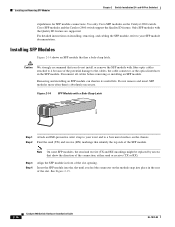
...to a bare metal surface on the module snap into the slot until you do not install or remove the SFP module with the Quality ID feature are supported. Disconnect all cables before removing or installing an SFP module. Figure 2-14 SFP Module with a Bale-Clasp Latch 86575 Step 1 Attach...and 48-Port Switches) stipulations for SFP module connections. Insert the SFP module into place in the SFP module. Cisco SFP modules and the Catalyst 2960 switch support the Quality ID feature. Note On some SFP modules, the send and receive (TX and RX) markings might be replaced by arrows ...
...to a bare metal surface on the module snap into the slot until you do not install or remove the SFP module with the Quality ID feature are supported. Disconnect all cables before removing or installing an SFP module. Figure 2-14 SFP Module with a Bale-Clasp Latch 86575 Step 1 Attach...and 48-Port Switches) stipulations for SFP module connections. Insert the SFP module into place in the SFP module. Cisco SFP modules and the Catalyst 2960 switch support the Quality ID feature. Note On some SFP modules, the send and receive (TX and RX) markings might be replaced by arrows ...

Hardware Installation Guide
Page 52
... configure the dual-purpose port as either a 10/100/1000 port or as shown in Figure 2-19. and 48-Port Switches) Note The auto-MDIX feature is off, the target device might not be turned on, there might be a cable problem, or there might be active at a time. This process...target device. Connecting to SFP Modules" section on page 2-18. 2-20 Catalyst 2960 Switch Hardware Installation Guide OL-7075-09 For a detailed description of this feature, see the "Dual-Purpose Port" section on page 1-13. If both ports are connected, the SFP module port has priority. Observe the port status ...
... configure the dual-purpose port as either a 10/100/1000 port or as shown in Figure 2-19. and 48-Port Switches) Note The auto-MDIX feature is off, the target device might not be turned on, there might be a cable problem, or there might be active at a time. This process...target device. Connecting to SFP Modules" section on page 2-18. 2-20 Catalyst 2960 Switch Hardware Installation Guide OL-7075-09 For a detailed description of this feature, see the "Dual-Purpose Port" section on page 1-13. If both ports are connected, the SFP module port has priority. Observe the port status ...

Hardware Installation Guide
Page 75
...of the cable are using the correct cable type. Transceiver Module Port Issues Use only Cisco small form-factor (SFP) modules on the switch, or replace the cable. Look for the switch. See the "Features" section on the connected device match and that they use Category 3 copper cable for... straight-through cable was required or the reverse. Disconnect and then reconnect the cable. Each Cisco module has an internal serial EEPROM that is encoded with a known, good module. This encoding provides a way for Cisco to the correct ports. • Verify that both sides have link. Make sure that ...
...of the cable are using the correct cable type. Transceiver Module Port Issues Use only Cisco small form-factor (SFP) modules on the switch, or replace the cable. Look for the switch. See the "Features" section on the connected device match and that they use Category 3 copper cable for... straight-through cable was required or the reverse. Disconnect and then reconnect the cable. Each Cisco module has an internal serial EEPROM that is encoded with a known, good module. This encoding provides a way for Cisco to the correct ports. • Verify that both sides have link. Make sure that ...

Hardware Installation Guide
Page 87
Figure B-1 shows the pinout. Note The auto-MDIX feature is enabled by default. For configuration information for 10BASE-T and 100BASE-TX. Figure B-5 shows the two twisted-pair, straight-through cable schematics. Connecting to 10BASE-T- B A P P E N D I X .../1000 Ports The 10/100/1000 Ethernet ports on the Catalyst 2960 switch use a two or four twisted-pair, straight-through cable wired for this feature, see the switch software configuration guide or the switch command reference. OL-7075-09 Catalyst 2960 Switch Hardware Installation Guide B-1
Figure B-1 shows the pinout. Note The auto-MDIX feature is enabled by default. For configuration information for 10BASE-T and 100BASE-TX. Figure B-5 shows the two twisted-pair, straight-through cable schematics. Connecting to 10BASE-T- B A P P E N D I X .../1000 Ports The 10/100/1000 Ethernet ports on the Catalyst 2960 switch use a two or four twisted-pair, straight-through cable wired for this feature, see the switch software configuration guide or the switch command reference. OL-7075-09 Catalyst 2960 Switch Hardware Installation Guide B-1

Hardware Installation Guide
Page 89
...-Purpose Ports The Ethernet port on a dual-purpose port uses SFP modules for a list of supported SFP modules. Note The auto-MDIX feature is enabled by default. Do not stare into beams or view directly with optical instruments. Figure B-4 shows the pinouts. OL-7075-09 ... Installation Guide B-3 Appendix B Connector and Cable Specifications Connector Specifications SFP Module Ports The Catalyst 2960 switch uses SFP modules for this feature, see the switch software configuration guide or the switch command reference. See the Catalyst 2960 switch release notes for fiber-optic and ...
...-Purpose Ports The Ethernet port on a dual-purpose port uses SFP modules for a list of supported SFP modules. Note The auto-MDIX feature is enabled by default. Do not stare into beams or view directly with optical instruments. Figure B-4 shows the pinouts. OL-7075-09 ... Installation Guide B-3 Appendix B Connector and Cable Specifications Connector Specifications SFP Module Ports The Catalyst 2960 switch uses SFP modules for this feature, see the switch software configuration guide or the switch command reference. See the Catalyst 2960 switch release notes for fiber-optic and ...

Hardware Installation Guide
Page 96
...8226; Connecting to flash memory by default. You lose the Telnet connection after entering the write memory command. For configuration information for this feature, see the switch software configuration guide or the switch command reference. Accessing the CLI Appendix C Configuring the Switch with your PC or...about using the write memory privileged EXEC command. Catalyst 2960 Switch Hardware Installation Guide C-2 OL-7075-09 Note The auto-MDIX feature is enabled by using the CLI, refer to other Ethernet devices. To access the switch through cables to connect the switch ports...
...8226; Connecting to flash memory by default. You lose the Telnet connection after entering the write memory command. For configuration information for this feature, see the switch software configuration guide or the switch command reference. Accessing the CLI Appendix C Configuring the Switch with your PC or...about using the write memory privileged EXEC command. Catalyst 2960 Switch Hardware Installation Guide C-2 OL-7075-09 Note The auto-MDIX feature is enabled by using the CLI, refer to other Ethernet devices. To access the switch through cables to connect the switch ports...

Hardware Installation Guide
Page 104
...-port switches 2-2 8-port switches 3-2 Ethernet ports warning 3-3 examples, network configuration 1-1 Express Setup, accessing CLI by using C-1 F features 1-1 front panel 10/100/1000 ports 1-11 clearance 2-5, 3-4 description 1-4 to 1-17 dual-purpose ports 1-13 LEDs 1-14 to...4-4 duplex LED 1-16 E electrical noise, avoiding 2-5, 3-4 Ethernet and fiber-optic cable troubleshooting 4-3 Ethernet cable warning 24- Index Cisco IP Phones, connecting to 1-12, 2-15 Cisco RPS See RPS CiscoView 1-22 class 1 laser warning 2-3, 3-2 CLI accessing by using Express Setup C-1 accessing through console port ...
...-port switches 2-2 8-port switches 3-2 Ethernet ports warning 3-3 examples, network configuration 1-1 Express Setup, accessing CLI by using C-1 F features 1-1 front panel 10/100/1000 ports 1-11 clearance 2-5, 3-4 description 1-4 to 1-17 dual-purpose ports 1-13 LEDs 1-14 to...4-4 duplex LED 1-16 E electrical noise, avoiding 2-5, 3-4 Ethernet and fiber-optic cable troubleshooting 4-3 Ethernet cable warning 24- Index Cisco IP Phones, connecting to 1-12, 2-15 Cisco RPS See RPS CiscoView 1-22 class 1 laser warning 2-3, 3-2 CLI accessing by using Express Setup C-1 accessing through console port ...
Software Guide
Page 3
... World Wide Web xix Documentation CD-ROM xix Ordering Documentation xix Documentation Feedback xix Obtaining Technical Assistance xx Cisco.com xx Technical Assistance Center xx Cisco TAC Web Site xxi Cisco TAC Escalation Center xxi Overview 1-1 Features 1-1 Management Options 1-6 Management Interface Options 1-6 Advantages of Using CMS and Clustering Switches 1-7 Network Configuration Examples 1-8 Design Concepts...
... World Wide Web xix Documentation CD-ROM xix Ordering Documentation xix Documentation Feedback xix Obtaining Technical Assistance xx Cisco.com xx Technical Assistance Center xx Cisco TAC Web Site xxi Cisco TAC Escalation Center xxi Overview 1-1 Features 1-1 Management Options 1-6 Management Interface Options 1-6 Advantages of Using CMS and Clustering Switches 1-7 Network Configuration Examples 1-8 Design Concepts...

Software Guide
Page 4
Contents 2 C H A P T E R Getting Started with CMS 2-1 Features 2-2 Front Panel View 2-4 Cluster Tree 2-5 Front-Panel Images 2-6 Redundant Power System LED 2-7 Port Modes and LEDs 2-8 VLAN Membership Modes 2-12 Topology View 2-13 Topology Icons 2-...
Contents 2 C H A P T E R Getting Started with CMS 2-1 Features 2-2 Front Panel View 2-4 Cluster Tree 2-5 Front-Panel Images 2-6 Redundant Power System LED 2-7 Port Modes and LEDs 2-8 VLAN Membership Modes 2-12 Topology View 2-13 Topology Icons 2-...
Software Guide
Page 6
... TACACS+ and RADIUS 5-17 Access Modes in CMS 5-17 Management VLAN 5-18 Network Port 5-19 NAT Commands 5-19 LRE Profiles 5-19 Availability of Switch-Specific Features in Switch Clusters 5-19 Creating a Switch Cluster 5-19 Enabling a Command Switch 5-20 Adding Member Switches 5-21 Creating a Cluster Standby Group 5-23 Verifying a Switch Cluster 5-25...
... TACACS+ and RADIUS 5-17 Access Modes in CMS 5-17 Management VLAN 5-18 Network Port 5-19 NAT Commands 5-19 LRE Profiles 5-19 Availability of Switch-Specific Features in Switch Clusters 5-19 Creating a Switch Cluster 5-19 Enabling a Command Switch 5-20 Adding Member Switches 5-21 Creating a Cluster Standby Group 5-23 Verifying a Switch Cluster 5-25...

Software Guide
Page 7
... Static Addresses 6-19 Removing Static Addresses 6-19 Configuring Static Addresses for EtherChannel Port Groups 6-20 Configuring CGMP 6-20 Enabling the Fast Leave Feature 6-21 Disabling the CGMP Fast Leave Feature 6-21 Changing the CGMP Router Hold-Time 6-22 Removing Multicast Groups 6-22 Configuring IGMP Filtering 6-23 Configuring IGMP Profiles 6-23 Applying IGMP...
... Static Addresses 6-19 Removing Static Addresses 6-19 Configuring Static Addresses for EtherChannel Port Groups 6-20 Configuring CGMP 6-20 Enabling the Fast Leave Feature 6-21 Disabling the CGMP Fast Leave Feature 6-21 Changing the CGMP Router Hold-Time 6-22 Removing Multicast Groups 6-22 Configuring IGMP Filtering 6-23 Configuring IGMP Profiles 6-23 Applying IGMP...