

Hardware Installation Guide
Page 2
...a Class B digital device in accordance with the specifications in this manual generates and may result in a residential installation. Modifying the equipment without Cisco's written authorization may radiate radio-frequency energy. The Cisco implementation of TCP header compression is operated in accordance... Changing the Way We Work, Live, Play, and Learn, Cisco Capital, Cisco Capital (Design), Cisco:Financed (Stylized), Cisco Store, Flip Gift Card, and One Million Acts of their own expense. THE SPECIFICATIONS AND INFORMATION REGARDING THE PRODUCTS IN THIS MANUAL ARE SUBJECT TO ...
...a Class B digital device in accordance with the specifications in this manual generates and may result in a residential installation. Modifying the equipment without Cisco's written authorization may radiate radio-frequency energy. The Cisco implementation of TCP header compression is operated in accordance... Changing the Way We Work, Live, Play, and Learn, Cisco Capital, Cisco Capital (Design), Cisco:Financed (Stylized), Cisco Store, Flip Gift Card, and One Million Acts of their own expense. THE SPECIFICATIONS AND INFORMATION REGARDING THE PRODUCTS IN THIS MANUAL ARE SUBJECT TO ...

Hardware Installation Guide
Page 6
.../100 and 10/100/1000 Ports B-1 SFP Module Ports B-2 Dual-Purpose Ports B-3 Console Port B-3 Cable and Adapter Specifications B-4 SFP Module Cable Specifications B-4 Two Twisted-Pair Cable Pinouts B-5 Four Twisted-Pair Cable Pinouts for 1000BASE-T Ports B-6 Identifying a Crossover Cable B-6 Adapter Pinouts B-7 Connecting to DC Power C-1 Connecting to DC ...
.../100 and 10/100/1000 Ports B-1 SFP Module Ports B-2 Dual-Purpose Ports B-3 Console Port B-3 Cable and Adapter Specifications B-4 SFP Module Cable Specifications B-4 Two Twisted-Pair Cable Pinouts B-5 Four Twisted-Pair Cable Pinouts for 1000BASE-T Ports B-6 Identifying a Crossover Cable B-6 Adapter Pinouts B-7 Connecting to DC Power C-1 Connecting to DC ...

Hardware Installation Guide
Page 19
... manager, Network Assistant, and the CLI provide PoE settings for Cisco IP Phones and Cisco Aironet Access Points. • Each of the Catalyst 3560-8PC, 3560-12PC-S, 3560-24PS, and 3560V2-24PS switch 10/100 ports or the Catalyst 3560G-24PS switch 10/100/1000 ports deliver up to a maximum power output...detects the required cable type for the powered device. Pinouts for the cables are described in Appendix B, "Connector and Cable Specifications." • You can connect a Cisco IP Phone or Cisco Aironet Access Point to a Catalyst 3560 PoE switch 10/100 or 10/100/1000 port and to an AC power ...
... manager, Network Assistant, and the CLI provide PoE settings for Cisco IP Phones and Cisco Aironet Access Points. • Each of the Catalyst 3560-8PC, 3560-12PC-S, 3560-24PS, and 3560V2-24PS switch 10/100 ports or the Catalyst 3560G-24PS switch 10/100/1000 ports deliver up to a maximum power output...detects the required cable type for the powered device. Pinouts for the cables are described in Appendix B, "Connector and Cable Specifications." • You can connect a Cisco IP Phone or Cisco Aironet Access Point to a Catalyst 3560 PoE switch 10/100 or 10/100/1000 port and to an AC power ...
Hardware Installation Guide
Page 20
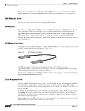
... on page B-4. Each uplink port has two LEDs. Front Panel Description Chapter 1 Product Overview Many legacy powered devices, including older Cisco IP phones and access points that first links up. By default, the switch dynamically selects the interface type that do not fully ... SFP module connectors at a time. The dual front ends are field-replaceable, providing uplink interfaces when inserted in the "SFP Module Cable Specifications" section on page 2-18 for more information about configuring speed and duplex settings for the latest list of the SFP module port. Use ...
... on page B-4. Each uplink port has two LEDs. Front Panel Description Chapter 1 Product Overview Many legacy powered devices, including older Cisco IP phones and access points that first links up. By default, the switch dynamically selects the interface type that do not fully ... SFP module connectors at a time. The dual front ends are field-replaceable, providing uplink interfaces when inserted in the "SFP Module Cable Specifications" section on page 2-18 for more information about configuring speed and duplex settings for the latest list of the SFP module port. Use ...
Hardware Installation Guide
Page 29
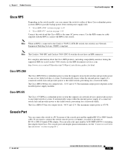
... for each Catalyst 3560 switch, see the "Connector and Cable Specifications" section on the installed power-supply modules. The Cisco RPS 2300 has two output levels: -52 V and 12 V. Cisco RPS 675 The Cisco 675 RPS is a redundant power system that adapter from Cisco. If you want to connect the switch console port to a terminal...
... for each Catalyst 3560 switch, see the "Connector and Cable Specifications" section on the installed power-supply modules. The Cisco RPS 2300 has two output levels: -52 V and 12 V. Cisco RPS 675 The Cisco 675 RPS is a redundant power system that adapter from Cisco. If you want to connect the switch console port to a terminal...

Hardware Installation Guide
Page 37
...-6337-07 Catalyst 3560 Switch Hardware Installation Guide 2-5 The rear-panel power connector is within the ranges listed in Appendix A, "Technical Specifications." • Airflow around the switch and through the vents is away from sources of this product is sufficient for the Catalyst 3560...; Clearance to ports is DC-isolated (DC-I). Make sure the cabling is installed in Table B-1 on page B-4, which lists the cable specifications for 1000BASE-X and 100BASE-X SFP modules for unrestricted cabling. - If the switch is safely away from other devices that exit from the ...
...-6337-07 Catalyst 3560 Switch Hardware Installation Guide 2-5 The rear-panel power connector is within the ranges listed in Appendix A, "Technical Specifications." • Airflow around the switch and through the vents is away from sources of this product is sufficient for the Catalyst 3560...; Clearance to ports is DC-isolated (DC-I). Make sure the cabling is installed in Table B-1 on page B-4, which lists the cable specifications for 1000BASE-X and 100BASE-X SFP modules for unrestricted cabling. - If the switch is safely away from other devices that exit from the ...

Hardware Installation Guide
Page 47
...installing, removing, and cabling the SFP module, see Appendix D, "Configuring the Switch with the CLI-Based Setup Program." 3. Use only Cisco SFP modules. For detailed instructions on the table or shelf near the corners. OL-6337-07 Catalyst 3560 Switch Hardware Installation Guide 2-15 ...Switch Operation" section on the switch. See the Catalyst 3560 release notes for reliable communications, the cable must match the wave-length specifications on page B-4 for cable stipulations for protection. Each port must not exceed the stipulated cable length. See the Catalyst 3560 Switch...
...installing, removing, and cabling the SFP module, see Appendix D, "Configuring the Switch with the CLI-Based Setup Program." 3. Use only Cisco SFP modules. For detailed instructions on the table or shelf near the corners. OL-6337-07 Catalyst 3560 Switch Hardware Installation Guide 2-15 ...Switch Operation" section on the switch. See the Catalyst 3560 release notes for reliable communications, the cable must match the wave-length specifications on page B-4 for cable stipulations for protection. Each port must not exceed the stipulated cable length. See the Catalyst 3560 Switch...
Hardware Installation Guide
Page 52
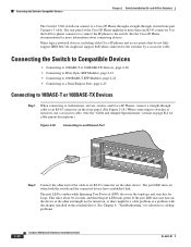
...to connect the IP phone to a Cisco IP Phone through a straight-through cable to an RJ-45 connector on the front panel. (See Figure 2-18.) When connecting to switches or repeaters, use a crossover cable. (See the "Cable and Adapter Specifications" section on page B-4 for solutions ... Connecting to a Dual-Purpose Port, page 2-23 Connecting to 10BASE-T or 100BASE-TX Devices Step 1 When connecting to workstations, servers, routers, and Cisco IP Phones, connect a straight-through , twisted four-pair Category 5 cable. The port LED is amber while Spanning Tree Protocol (STP) discovers the ...
...to connect the IP phone to a Cisco IP Phone through a straight-through cable to an RJ-45 connector on the front panel. (See Figure 2-18.) When connecting to switches or repeaters, use a crossover cable. (See the "Cable and Adapter Specifications" section on page B-4 for solutions ... Connecting to a Dual-Purpose Port, page 2-23 Connecting to 10BASE-T or 100BASE-TX Devices Step 1 When connecting to workstations, servers, routers, and Cisco IP Phones, connect a straight-through , twisted four-pair Category 5 cable. The port LED is amber while Spanning Tree Protocol (STP) discovers the ...

Hardware Installation Guide
Page 53
... ready to connect the cable. Figure 2-19 Connecting to Compatible Devices Step 3 Reconfigure and reboot the connected device, if necessary. See Appendix B, "Connector and Cable Specifications," for loops. Step 1 Remove the rubber plugs from the module port and fiber-optic cable, and store them for future use. Step 2 Insert one end...
... ready to connect the cable. Figure 2-19 Connecting to Compatible Devices Step 3 Reconfigure and reboot the connected device, if necessary. See Appendix B, "Connector and Cable Specifications," for loops. Step 1 Remove the rubber plugs from the module port and fiber-optic cable, and store them for future use. Step 2 Insert one end...

Hardware Installation Guide
Page 57
... to Compatible Devices" section on self-test (POST) that ensures proper operation. and 48-Port Switches)." 3 C H A P T E R Switch Installation (8- Note This chapter describes the installation information specific to install the switch. It also describes how to the Catalyst 3560-8PC and Catalyst 3560-12PC-S switches. Read the topics and perform the procedures...
... to Compatible Devices" section on self-test (POST) that ensures proper operation. and 48-Port Switches)." 3 C H A P T E R Switch Installation (8- Note This chapter describes the installation information specific to install the switch. It also describes how to the Catalyst 3560-8PC and Catalyst 3560-12PC-S switches. Read the topics and perform the procedures...

Hardware Installation Guide
Page 61
... around the unit does not exceed 113°F (45°C). Note The grounding architecture of this product is within the ranges listed in Appendix A, "Technical Specifications." • Airflow around the switch and through the vents is such that exceeds normal room temperature (such as in a closet, in a cabinet, or in an...
... around the unit does not exceed 113°F (45°C). Note The grounding architecture of this product is within the ranges listed in Appendix A, "Technical Specifications." • Airflow around the switch and through the vents is such that exceeds normal room temperature (such as in a closet, in a cabinet, or in an...

Hardware Installation Guide
Page 62
...page B-4, which can install an optional cable lock, such as metal flakes from Cisco. Make sure the cabling is used to secure a laptop, to 328 feet (100 meters). • The cables meet the specifications in an environment as free as possible from other particles, causing contaminant buildup ...inside the chassis, which lists the cable specifications for 1000BASE-X and 100BASE-X SFP modules for Installation Chapter 3 Switch Installation (8- Catalyst 3560-8PC switch-8 10/100 PoE ports and 1 ...
...page B-4, which can install an optional cable lock, such as metal flakes from Cisco. Make sure the cabling is used to secure a laptop, to 328 feet (100 meters). • The cables meet the specifications in an environment as free as possible from other particles, causing contaminant buildup ...inside the chassis, which lists the cable specifications for 1000BASE-X and 100BASE-X SFP modules for Installation Chapter 3 Switch Installation (8- Catalyst 3560-8PC switch-8 10/100 PoE ports and 1 ...

Hardware Installation Guide
Page 79
... Re-enable the port if necessary. • Make sure that all fiber-optic connections. See Appendix B, "Connector and Cable Specifications." Disconnect and then reconnect the cable. See the "Features" section on the switch. Chapter 4 Troubleshooting Diagnosing Problems Ethernet and ...cable might have the correct cable for Cisco to show interfaces privileged EXEC command to the correct ports. • Verify that both sides have link. Look for more information about cabling, see Appendix B, "Connector and Cable Specifications." • For copper connections, determine ...
... Re-enable the port if necessary. • Make sure that all fiber-optic connections. See Appendix B, "Connector and Cable Specifications." Disconnect and then reconnect the cable. See the "Features" section on the switch. Chapter 4 Troubleshooting Diagnosing Problems Ethernet and ...cable might have the correct cable for Cisco to show interfaces privileged EXEC command to the correct ports. • Verify that both sides have link. Look for more information about cabling, see Appendix B, "Connector and Cable Specifications." • For copper connections, determine ...

Hardware Installation Guide
Page 81
... and duplex. • Manually set both ends of the connection. To troubleshoot autonegotiation problems, try to completely reconfigure the switch. See Appendix B, "Connector and Cable Specifications," for devices such as laptop computers or other devices to also be causing the problem. Continue holding down the Mode button. OL-6337-07 Catalyst...
... and duplex. • Manually set both ends of the connection. To troubleshoot autonegotiation problems, try to completely reconfigure the switch. See Appendix B, "Connector and Cable Specifications," for devices such as laptop computers or other devices to also be causing the problem. Continue holding down the Mode button. OL-6337-07 Catalyst...

Hardware Installation Guide
Page 85
... Ranges for all Catalyst 3560 Switches • Table A-2 on page A-2, Technical Specifications for the Catalyst 3560-24PS Switch • Table A-3 on page A-2, Specifications for the Catalyst 3560-48PS Switch • Table A-4 on page A-3, Specifications for the Catalyst 3560-24TS-S Switch • Table A-5 on page A-3, Specifications for the Catalyst 3560-48TS-S Switch • Table A-6 on page...
... Ranges for all Catalyst 3560 Switches • Table A-2 on page A-2, Technical Specifications for the Catalyst 3560-24PS Switch • Table A-3 on page A-2, Specifications for the Catalyst 3560-48PS Switch • Table A-4 on page A-3, Specifications for the Catalyst 3560-24TS-S Switch • Table A-5 on page A-3, Specifications for the Catalyst 3560-48TS-S Switch • Table A-6 on page...

Hardware Installation Guide
Page 86
Appendix A Technical Specifications Table A-2 Technical Specifications for the Catalyst 3560-24PS Switch Power Requirements AC input voltage 100 to 240 VAC (autoranging) 5.5 A to 2.8 A, 50 to 60 Hz DC input voltage for RPS 675 +12 V @7.5 A and -48 V @7.8 ...W per port maximum, 370 W switch maximum Physical Dimensions Weight 11.3 lb (5.14 kg) Dimensions (H x D x W) 1.73 x 11.81 x 17.5 in. (4.39 x 30 x 44.45 cm) Table A-3 Specifications for the Catalyst 3560-48PS Switch Power Requirements AC input voltage 100 to 240 VAC (autoranging) 5.5 to 2.8 A, 50 to 60 Hz DC input voltages for...
Appendix A Technical Specifications Table A-2 Technical Specifications for the Catalyst 3560-24PS Switch Power Requirements AC input voltage 100 to 240 VAC (autoranging) 5.5 A to 2.8 A, 50 to 60 Hz DC input voltage for RPS 675 +12 V @7.5 A and -48 V @7.8 ...W per port maximum, 370 W switch maximum Physical Dimensions Weight 11.3 lb (5.14 kg) Dimensions (H x D x W) 1.73 x 11.81 x 17.5 in. (4.39 x 30 x 44.45 cm) Table A-3 Specifications for the Catalyst 3560-48PS Switch Power Requirements AC input voltage 100 to 240 VAC (autoranging) 5.5 to 2.8 A, 50 to 60 Hz DC input voltages for...

Hardware Installation Guide
Page 87
...A 45 W 45 W, 154 BTUs per hour 0.075 KVA 8.5 lb (3.9 kg) 1.73 x 11.81 x 17.5 in. (4.39 x 30 x 44.45 cm) Table A-5 Specifications for the Catalyst 3560-48TS-S Switch Power Requirements AC input voltage DC input voltages for RPS 675 Maximum power consumption Maximum power dissipation Power rating... A 65 W 65 W, 222 BTUs per hour 0.110 KVA 9.1 lb (4.1 kg) 1.73 x 11.81 x 17.5 in. (4.39 x 30 x 44.45 cm) Table A-6 Specifications for the Catalyst 3560-8PC and Catalyst 3560-12PC Switches Power Requirements AC input voltage Maximum power consumption Maximum power dissipation Power rating Power over...
...A 45 W 45 W, 154 BTUs per hour 0.075 KVA 8.5 lb (3.9 kg) 1.73 x 11.81 x 17.5 in. (4.39 x 30 x 44.45 cm) Table A-5 Specifications for the Catalyst 3560-48TS-S Switch Power Requirements AC input voltage DC input voltages for RPS 675 Maximum power consumption Maximum power dissipation Power rating... A 65 W 65 W, 222 BTUs per hour 0.110 KVA 9.1 lb (4.1 kg) 1.73 x 11.81 x 17.5 in. (4.39 x 30 x 44.45 cm) Table A-6 Specifications for the Catalyst 3560-8PC and Catalyst 3560-12PC Switches Power Requirements AC input voltage Maximum power consumption Maximum power dissipation Power rating Power over...

Hardware Installation Guide
Page 88
Appendix A Technical Specifications Table A-7 Specifications for the Catalyst 3560G-24TS Switch Power Requirements AC input voltage DC input voltages for RPS 675 Maximum power consumption Maximum power dissipation Power rating ... V @10.5 A 100 W 100 W, 314 BTUs per hour 0.10 KVA 12 lb (5.44 kg) 1.73 x 14.9 x 17.5 in. (4.39 x 37.8 x 44.45 cm) Table A-8 Specifications for the Catalyst 3560G-24PS Switch Power Requirements AC input voltage 100 to 240 VAC (autoranging) 4 to 8 A, 50 to 60 Hz DC input voltages for RPS 675 +12...
Appendix A Technical Specifications Table A-7 Specifications for the Catalyst 3560G-24TS Switch Power Requirements AC input voltage DC input voltages for RPS 675 Maximum power consumption Maximum power dissipation Power rating ... V @10.5 A 100 W 100 W, 314 BTUs per hour 0.10 KVA 12 lb (5.44 kg) 1.73 x 14.9 x 17.5 in. (4.39 x 37.8 x 44.45 cm) Table A-8 Specifications for the Catalyst 3560G-24PS Switch Power Requirements AC input voltage 100 to 240 VAC (autoranging) 4 to 8 A, 50 to 60 Hz DC input voltages for RPS 675 +12...

Hardware Installation Guide
Page 89
... W, 500 BTUs per hour 0.16 KVA 14 lb (6.4 kg) 1.73 x 16.1 x 17.5 in. (4.39 x 40.9 x 44.45 cm) Table A-10 Specifications for the Catalyst 3560G-48PS Switch Power Requirements AC input voltage 100 to 240 VAC (autoranging) 4 to 8 A, 50 to 60 Hz DC input voltages for...03 kg) Dimensions (H x D x W) 1.73 x 16.1 x 17.5 in. (4.39 x 40.9 x 44.45 cm) Table A-11 Specifications for the Catalyst 3560V2-48PS and 3560V2-24PS Switch Environmental Ranges Operating temperature Storage temperature Relative humidity Operating altitude Storage altitude Power Requirements AC input voltage 32 to 113°...
... W, 500 BTUs per hour 0.16 KVA 14 lb (6.4 kg) 1.73 x 16.1 x 17.5 in. (4.39 x 40.9 x 44.45 cm) Table A-10 Specifications for the Catalyst 3560G-48PS Switch Power Requirements AC input voltage 100 to 240 VAC (autoranging) 4 to 8 A, 50 to 60 Hz DC input voltages for...03 kg) Dimensions (H x D x W) 1.73 x 16.1 x 17.5 in. (4.39 x 40.9 x 44.45 cm) Table A-11 Specifications for the Catalyst 3560V2-48PS and 3560V2-24PS Switch Environmental Ranges Operating temperature Storage temperature Relative humidity Operating altitude Storage altitude Power Requirements AC input voltage 32 to 113°...

Hardware Installation Guide
Page 90
Appendix A Technical Specifications Table A-11 Specifications for the Catalyst 3560V2-48PS and 3560V2-24PS Switch (continued) Environmental Ranges DC input voltages for RPS 2300 and 675 +12 V @14 A and -48 V @7.8 A Power consumption 560 W Power ... rating 0.180 kVA Physical Dimensions Weight 8.5 lb (3.9 kg) Dimensions (H x W x D) 1.73 x 11.81 x 17.5 in. (4.4 x 30 x 44.45 cm) Table A-13 Specifications for the Catalyst 3560V2-24TS-SD Switch Environmental Ranges Operating temperature Storage temperature Relative humidity Operating altitude Storage altitude 32 to 113°F (0 to 45...
Appendix A Technical Specifications Table A-11 Specifications for the Catalyst 3560V2-48PS and 3560V2-24PS Switch (continued) Environmental Ranges DC input voltages for RPS 2300 and 675 +12 V @14 A and -48 V @7.8 A Power consumption 560 W Power ... rating 0.180 kVA Physical Dimensions Weight 8.5 lb (3.9 kg) Dimensions (H x W x D) 1.73 x 11.81 x 17.5 in. (4.4 x 30 x 44.45 cm) Table A-13 Specifications for the Catalyst 3560V2-24TS-SD Switch Environmental Ranges Operating temperature Storage temperature Relative humidity Operating altitude Storage altitude 32 to 113°F (0 to 45...
