
Hardware Installation Guide
Page 3
... RPS LED 1-12 Port LEDs and Modes 1-13 Dual-Purpose Port LEDs 1-15 Cable Guard 1-15 Rear Panel Description 1-15 Internal Power Supply 1-18 DC Power Connector 1-18 Cisco RPS 1-19 Cisco RPS 2300 1-19 Cisco RPS 675 1-19 Console Port 1-19 Security Slots 1-20 Management Options 1-20 Catalyst 3560 Switch Hardware Installation Guide iii
... RPS LED 1-12 Port LEDs and Modes 1-13 Dual-Purpose Port LEDs 1-15 Cable Guard 1-15 Rear Panel Description 1-15 Internal Power Supply 1-18 DC Power Connector 1-18 Cisco RPS 1-19 Cisco RPS 2300 1-19 Cisco RPS 675 1-19 Console Port 1-19 Security Slots 1-20 Management Options 1-20 Catalyst 3560 Switch Hardware Installation Guide iii

Hardware Installation Guide
Page 4
... (8- Contents 2 C H A P T E R 3 C H A P T E R Network Configurations 1-21 Switch Installation (24- and 48-Port Switches) 2-1 Preparing for Installation 2-1 Warnings 2-2 Installation Guidelines 2-5 Box Contents 2-6 Tools and Equipment 2-6 Verifying Switch Operation 2-6 Powering Off the Switch 2-7 Installing the Switch 2-7 Rack-Mounting 2-7 Removing Screws from SFP Module Slots 2-17 Inserting and Removing the SFP Module Patch Cable 2-18 10...
... (8- Contents 2 C H A P T E R 3 C H A P T E R Network Configurations 1-21 Switch Installation (24- and 48-Port Switches) 2-1 Preparing for Installation 2-1 Warnings 2-2 Installation Guidelines 2-5 Box Contents 2-6 Tools and Equipment 2-6 Verifying Switch Operation 2-6 Powering Off the Switch 2-7 Installing the Switch 2-7 Rack-Mounting 2-7 Removing Screws from SFP Module Slots 2-17 Inserting and Removing the SFP Module Patch Cable 2-18 10...

Hardware Installation Guide
Page 5
4 C H A P T E R Box Contents 3-7 Tools and Equipment 3-7 Verifying Switch Operation 3-7 Powering Off the Switch 3-7 Installing the Switch 3-7 Desk or Shelf Mounting 3-8 Desk or Shelf Mounting (Unsecured) 3-8 Desk or Shelf Mounting (Secured) 3-8 Under the Desk ... 3-16 Attaching Brackets to the Switch 3-16 Mounting the Switch in a 19-Inch Rack 3-17 Wall-Mounting (with Rack-Mount Brackets) 3-17 Securing the AC Power Cord 3-19 Where to Go Next 3-20 Troubleshooting 4-1 Diagnosing Problems 4-1 Evaluate Switch POST Results 4-2 Monitor Switch LEDs 4-2 Verify Switch Connections 4-2 Bad or Damaged Cable ...
4 C H A P T E R Box Contents 3-7 Tools and Equipment 3-7 Verifying Switch Operation 3-7 Powering Off the Switch 3-7 Installing the Switch 3-7 Desk or Shelf Mounting 3-8 Desk or Shelf Mounting (Unsecured) 3-8 Desk or Shelf Mounting (Secured) 3-8 Under the Desk ... 3-16 Attaching Brackets to the Switch 3-16 Mounting the Switch in a 19-Inch Rack 3-17 Wall-Mounting (with Rack-Mount Brackets) 3-17 Securing the AC Power Cord 3-19 Where to Go Next 3-20 Troubleshooting 4-1 Diagnosing Problems 4-1 Evaluate Switch POST Results 4-2 Monitor Switch LEDs 4-2 Verify Switch Connections 4-2 Bad or Damaged Cable ...

Hardware Installation Guide
Page 6
... Cable Pinouts B-5 Four Twisted-Pair Cable Pinouts for 1000BASE-T Ports B-6 Identifying a Crossover Cable B-6 Adapter Pinouts B-7 Connecting to DC Power C-1 Connecting to DC Power C-1 Preparing for Installation C-2 Grounding the Switch C-2 Wiring the DC-Input Power Source C-5 Configuring the Switch with the CLI-Based Setup Program D-1 Preparing for Setup D-1 Completing the Setup Program D-3 Catalyst 3560...
... Cable Pinouts B-5 Four Twisted-Pair Cable Pinouts for 1000BASE-T Ports B-6 Identifying a Crossover Cable B-6 Adapter Pinouts B-7 Connecting to DC Power C-1 Connecting to DC Power C-1 Preparing for Installation C-2 Grounding the Switch C-2 Wiring the DC-Input Power Source C-5 Configuring the Switch with the CLI-Based Setup Program D-1 Preparing for Setup D-1 Completing the Setup Program D-3 Catalyst 3560...

Hardware Installation Guide
Page 8
... Guide viii OL-6337-07 Related Publications These documents provide complete information about related products, see the release notes on Cisco.com for the latest information. • Catalyst 3560 Switch Software Configuration Guide • Catalyst 3560 Switch Command Reference ... Safety Information for Cisco Network Assistant • Cisco Small Form-Factor Pluggable Modules Installation Notes • Cisco CWDM GBIC and CWDM SFP Installation Note • Cisco RPS 2300 Redundant Power System Hardware Installation Guide • Cisco RPS 675 Redundant Power System Hardware Installation...
... Guide viii OL-6337-07 Related Publications These documents provide complete information about related products, see the release notes on Cisco.com for the latest information. • Catalyst 3560 Switch Software Configuration Guide • Catalyst 3560 Switch Command Reference ... Safety Information for Cisco Network Assistant • Cisco Small Form-Factor Pluggable Modules Installation Notes • Cisco CWDM GBIC and CWDM SFP Installation Note • Cisco RPS 2300 Redundant Power System Hardware Installation Guide • Cisco RPS 675 Redundant Power System Hardware Installation...

Hardware Installation Guide
Page 11
...you can connect devices like workstations, Cisco Wireless Access Points, Cisco IP Phones, and other network devices such as servers, routers, and other network devices. The Catalyst 3560-8PC and the Catalyst 3560-12PC-S compact switches provide the same Power over Ethernet (PoE) connectivity and ...Hardware Installation Guide 1-1 Features The 24- See the switch software configuration guide for an optional Cisco RPS 2300 or Cisco RPS 675 that operates on AC power and supplies backup DC power to initially configure your switch using the command-line interface (CLI), see Appendix D, "...
...you can connect devices like workstations, Cisco Wireless Access Points, Cisco IP Phones, and other network devices such as servers, routers, and other network devices. The Catalyst 3560-8PC and the Catalyst 3560-12PC-S compact switches provide the same Power over Ethernet (PoE) connectivity and ...Hardware Installation Guide 1-1 Features The 24- See the switch software configuration guide for an optional Cisco RPS 2300 or Cisco RPS 675 that operates on AC power and supplies backup DC power to initially configure your switch using the command-line interface (CLI), see Appendix D, "...

Hardware Installation Guide
Page 12
... (only Catalyst 3560 8- Features Chapter 1 Product Overview Table 1-1 Catalyst 3560 Switch Model Descriptions Switch Model Description FastEthernet Catalyst 3560-24PS 24 10/100 Power over Ethernet (PoE) ports and 2 small form-factor pluggable (SFP) module slots Catalyst 3560-24TS-S 24 10/100 ports ... • 1000BASE-ZX • Coarse Wavelength-Division Multiplexing (CWDM) • SFP module patch cable. (CAB-SFP-50CM=.) Switches running Cisco IOS Release 12.2(25)SEB or later support this patch cable. Supported SFP modules: • 100BASE-BX10 (only Catalyst 3560 8- Catalyst ...
... (only Catalyst 3560 8- Features Chapter 1 Product Overview Table 1-1 Catalyst 3560 Switch Model Descriptions Switch Model Description FastEthernet Catalyst 3560-24PS 24 10/100 Power over Ethernet (PoE) ports and 2 small form-factor pluggable (SFP) module slots Catalyst 3560-24TS-S 24 10/100 ports ... • 1000BASE-ZX • Coarse Wavelength-Division Multiplexing (CWDM) • SFP module patch cable. (CAB-SFP-50CM=.) Switches running Cisco IOS Release 12.2(25)SEB or later support this patch cable. Supported SFP modules: • 100BASE-BX10 (only Catalyst 3560 8- Catalyst ...

Hardware Installation Guide
Page 18
.../s. If the connected device also supports autonegotiation, the switch port negotiates the best connection (the fastest line speed that present a shock hazard may exist on Power over Ethernet (PoE) circuits if interconnections are numbered 49 to 52. In all cases, the attached device must be accessed only through the use Category...
.../s. If the connected device also supports autonegotiation, the switch port negotiates the best connection (the fastest line speed that present a shock hazard may exist on Power over Ethernet (PoE) circuits if interconnections are numbered 49 to 52. In all cases, the attached device must be accessed only through the use Category...

Hardware Installation Guide
Page 19
...PoE settings for Cisco IP Phones and Cisco Aironet Access Points. • Each of the Catalyst 3560-8PC, 3560-12PC-S, 3560-24PS, and 3560V2-24PS switch 10/100 ports or the Catalyst 3560G-24PS switch 10/100/1000 ports deliver up to a maximum power output of approximately 125 W total PoE power. • On...either a crossover or a straight-through cable for proper operation. If the primary source fails, the second power source becomes the primary power source to the powered device. For releases between Cisco IOS Release 12.1(14)EA1 and 12.2(18)SE, the auto-MDIX feature is enabled by default. ...
...PoE settings for Cisco IP Phones and Cisco Aironet Access Points. • Each of the Catalyst 3560-8PC, 3560-12PC-S, 3560-24PS, and 3560V2-24PS switch 10/100 ports or the Catalyst 3560G-24PS switch 10/100/1000 ports deliver up to a maximum power output of approximately 125 W total PoE power. • On...either a crossover or a straight-through cable for proper operation. If the primary source fails, the second power source becomes the primary power source to the powered device. For releases between Cisco IOS Release 12.1(14)EA1 and 12.2(18)SE, the auto-MDIX feature is enabled by default. ...
Hardware Installation Guide
Page 20
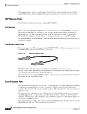
... shows the status of the RJ-45 port, and one connector of supported SFP modules. Front Panel Description Chapter 1 Product Overview Many legacy powered devices, including older Cisco IP phones and access points that first links up. Figure 1-11 SFP Module Patch Cable 126809 The SFP module patch cable can use the...
... shows the status of the RJ-45 port, and one connector of supported SFP modules. Front Panel Description Chapter 1 Product Overview Many legacy powered devices, including older Cisco IP phones and access points that first links up. Figure 1-11 SFP Module Patch Cable 126809 The SFP module patch cable can use the...

Hardware Installation Guide
Page 21
...switches. 2. Table 1-2 Color Off Green Amber System LED System Status System is only on . For information on the System LED colors during the power-on self-test (POST), see the "Verifying Switch Operation" section on page 2-6. The switch online help describes how to use to select one of... the port modes. OL-6337-07 Catalyst 3560 Switch Hardware Installation Guide 1-11 System is not functioning properly. System is receiving power but is operating normally. Figure 1-12 shows the switch LEDs and the Mode button that you use the device manager or Network Assistant to...
...switches. 2. Table 1-2 Color Off Green Amber System LED System Status System is only on . For information on the System LED colors during the power-on self-test (POST), see the "Verifying Switch Operation" section on page 2-6. The switch online help describes how to use to select one of... the port modes. OL-6337-07 Catalyst 3560 Switch Hardware Installation Guide 1-11 System is not functioning properly. System is receiving power but is operating normally. Figure 1-12 shows the switch LEDs and the Mode button that you use the device manager or Network Assistant to...
Hardware Installation Guide
Page 22
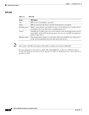
... to provide back-up power, if required. RPS is connected but is unavailable because it does not, the RPS fan might have an RPS LED. Contact Cisco. For more information about the Cisco RPS 2300 and the RPS 675, see the Cisco Redundant Power System 2300 Hardware Installation Guide... and the Cisco RPS 675 Redundant Power System Hardware Installation Guide. 1-12 Catalyst 3560 Switch Hardware Installation...
... to provide back-up power, if required. RPS is connected but is unavailable because it does not, the RPS fan might have an RPS LED. Contact Cisco. For more information about the Cisco RPS 2300 and the RPS 675, see the Cisco Redundant Power System 2300 Hardware Installation Guide... and the Cisco RPS 675 Redundant Power System Hardware Installation Guide. 1-12 Catalyst 3560 Switch Hardware Installation...

Hardware Installation Guide
Page 23
... PoE status. 1. Even if the PoE mode is highlighted. None of the 10/100 or 10/100/1000 PoE ports has been denied power, or at 10 or 100 Mb/s in a fault condition. PoE mode is selected, and the PoE status is not selected. The port operating speed: 10, ... the port LED colors in full-duplex mode or at least one of the 10/100 or 10/100/1000 PoE ports have been denied power or are detected. PoE mode is shown on the port LEDs. When you change a mode, press the Mode button until the desired mode is not...
... PoE status. 1. Even if the PoE mode is highlighted. None of the 10/100 or 10/100/1000 PoE ports has been denied power, or at 10 or 100 Mb/s in a fault condition. PoE mode is selected, and the PoE status is not selected. The port operating speed: 10, ... the port LED colors in full-duplex mode or at least one of the 10/100 or 10/100/1000 PoE ports have been denied power or are detected. PoE mode is shown on the port LEDs. When you change a mode, press the Mode button until the desired mode is not...

Hardware Installation Guide
Page 24
... and jabber errors are connected to PoE ports. Note When installed in Catalyst 3560 switches, 1000BASE-T SFP modules can be used to connect Cisco prestandard IP Phones or wireless access points or IEEE 802.3af-compliant devices to a PoE port. Front Panel Description Chapter 1 Product Overview ...the network topology for up to a fault. STAT (port status) DUPLX (duplex) SPEED Caution PoE faults are caused when noncompliant cabling or powered devices are monitored for the port has been disabled. Note After a port is enabled. Green Port is operating at 1000 Mb/s. Green ...
... and jabber errors are connected to PoE ports. Note When installed in Catalyst 3560 switches, 1000BASE-T SFP modules can be used to connect Cisco prestandard IP Phones or wireless access points or IEEE 802.3af-compliant devices to a PoE port. Front Panel Description Chapter 1 Product Overview ...the network topology for up to a fault. STAT (port status) DUPLX (duplex) SPEED Caution PoE faults are caused when noncompliant cabling or powered devices are monitored for the port has been disabled. Note After a port is enabled. Green Port is operating at 1000 Mb/s. Green ...
Hardware Installation Guide
Page 25
...-6337-07 Catalyst 3560 Switch Hardware Installation Guide 1-15 The LED colors have an RPS connector or a fan. Rear Panel Description • Internal Power Supply, page 1-18 • Cisco RPS, page 1-19 • Console Port, page 1-19 • Security Slots, page 1-20 Note The Catalyst 3560-8PC and the Catalyst 3560-12PC... (see Figure 1-13) show how the port is on the front panel. To order a cable guard (CBLGRD-C3560-12PC or CBLGRD-C3560-8PC), contact your Cisco representative. The switch console port is being accidentally removed.
...-6337-07 Catalyst 3560 Switch Hardware Installation Guide 1-15 The LED colors have an RPS connector or a fan. Rear Panel Description • Internal Power Supply, page 1-18 • Cisco RPS, page 1-19 • Console Port, page 1-19 • Security Slots, page 1-20 Note The Catalyst 3560-8PC and the Catalyst 3560-12PC... (see Figure 1-13) show how the port is on the front panel. To order a cable guard (CBLGRD-C3560-12PC or CBLGRD-C3560-8PC), contact your Cisco representative. The switch console port is being accidentally removed.

Hardware Installation Guide
Page 26
... CONSOLE 5.0A1-20R.05A-A2T,0IN500GV-6~0 HZ [email protected]@YMUO7A.TL8EA 97914 1 2 3 4 1 RJ-45 console port 3 RPS connector 2 AC power connector 4 Fan exhaust Figure 1-15 Catalyst 3560G-24PS, 3560G-48PS, 3560G-24TS, and 3560G-48TS Switch Rear Panel 119678 CONSOLE DSCPIENPCPOIUWFTIEESDRFISONURMPRPAELNYMUOATLE 12 3 4 1 RJ-45 console port 3 RPS connector 2 Fan exhaust...
... CONSOLE 5.0A1-20R.05A-A2T,0IN500GV-6~0 HZ [email protected]@YMUO7A.TL8EA 97914 1 2 3 4 1 RJ-45 console port 3 RPS connector 2 AC power connector 4 Fan exhaust Figure 1-15 Catalyst 3560G-24PS, 3560G-48PS, 3560G-24TS, and 3560G-48TS Switch Rear Panel 119678 CONSOLE DSCPIENPCPOIUWFTIEESDRFISONURMPRPAELNYMUOATLE 12 3 4 1 RJ-45 console port 3 RPS connector 2 Fan exhaust...

Hardware Installation Guide
Page 27
Chapter 1 Product Overview Rear Panel Description Figure 1-16 Catalyst 3560V2-24PS, 3560V2-48PS, 3560V2-24TS, 3560V2-48TS Switch Rear Panel 274670 CONSOLE 1 2 3 4 1 RJ-45 console port 2 Fan exhaust 3 RPS connector 4 AC power connector Figure 1-17 Catalyst 3560V2-24TS-SD Switch Rear Panel 274671 CONSOLE 12 3 4 1 RJ-45 console port 2 Fan exhaust 3 RPS connector 4 DC power connector OL-6337-07 Catalyst 3560 Switch Hardware Installation Guide 1-17
Chapter 1 Product Overview Rear Panel Description Figure 1-16 Catalyst 3560V2-24PS, 3560V2-48PS, 3560V2-24TS, 3560V2-48TS Switch Rear Panel 274670 CONSOLE 1 2 3 4 1 RJ-45 console port 2 Fan exhaust 3 RPS connector 4 AC power connector Figure 1-17 Catalyst 3560V2-24TS-SD Switch Rear Panel 274671 CONSOLE 12 3 4 1 RJ-45 console port 2 Fan exhaust 3 RPS connector 4 DC power connector OL-6337-07 Catalyst 3560 Switch Hardware Installation Guide 1-17

Hardware Installation Guide
Page 28
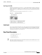
... B) that has an input supply voltage from -36 to a DC-input power source that are diode-OR-ed into a single power block. Use the supplied AC power cord to connect the AC power connector to DC Power." The internal power supply is not in this range, the switch might not operate properly or ... Installation Guide OL-6337-07 Rear Panel Description Chapter 1 Product Overview The Catalyst 3560-8PC and Catalyst 3560-12PC-S rear panels have an AC power connector and heat sinks. (See Figure 1-18.) Figure 1-18 Catalyst 3560-8PC and Catalyst 3560-12PC-S Switch Rear Panel 250607 1 2 1 Heat sinks...
... B) that has an input supply voltage from -36 to a DC-input power source that are diode-OR-ed into a single power block. Use the supplied AC power cord to connect the AC power connector to DC Power." The internal power supply is not in this range, the switch might not operate properly or ... Installation Guide OL-6337-07 Rear Panel Description Chapter 1 Product Overview The Catalyst 3560-8PC and Catalyst 3560-12PC-S rear panels have an AC power connector and heat sinks. (See Figure 1-18.) Figure 1-18 Catalyst 3560-8PC and Catalyst 3560-12PC-S Switch Rear Panel 250607 1 2 1 Heat sinks...
Hardware Installation Guide
Page 29
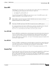
... products, including compatibility matrixes listing the supported RPS for each Catalyst 3560 switch, see the "Connector and Cable Specifications" section on the installed power-supply modules. The Cisco RPS 675 has two output levels: -48 V and 12 V. Console Port You can connect the switch to a PC by means of network traffic. OL...
... products, including compatibility matrixes listing the supported RPS for each Catalyst 3560 switch, see the "Connector and Cable Specifications" section on the installed power-supply modules. The Cisco RPS 675 has two output levels: -48 V and 12 V. Console Port You can connect the switch to a PC by means of network traffic. OL...

Hardware Installation Guide
Page 33
... Installation (8- The instructions in this chapter for connecting to the switch ports and for installing, and connecting to the SFP modules apply to interpret the power-on self-test (POST) that ensures proper operation. and 48-Port Switches) This chapter describes how to the switch. and 48-port switches, including how...
... Installation (8- The instructions in this chapter for connecting to the switch ports and for installing, and connecting to the SFP modules apply to interpret the power-on self-test (POST) that ensures proper operation. and 48-Port Switches) This chapter describes how to the switch. and 48-port switches, including how...


