
Hardware Installation Guide
Page 4
... SFP Modules from the Switch 2-8 Attaching Brackets to the Catalyst 3560 Switch 2-8 Mounting the Switch in a Rack 2-10 Attaching the Cable Guide 2-11 Wall-Mounting 2-12 Attaching the Brackets to Go Next 2-24 Switch Installation (8- and 12-Port Switches) 3-1 Preparing for...a Wall 2-14 Table- or Shelf- Contents 2 C H A P T E R 3 C H A P T E R Network Configurations 1-21 Switch Installation (24- and 48-Port Switches) 2-1 Preparing for Installation 3-1 Warnings 3-2 Installation Guidelines 3-5 Equipment That You Supply 3-6 Catalyst 3560 Switch Hardware Installation Guide iv OL-6337-07
... SFP Modules from the Switch 2-8 Attaching Brackets to the Catalyst 3560 Switch 2-8 Mounting the Switch in a Rack 2-10 Attaching the Cable Guide 2-11 Wall-Mounting 2-12 Attaching the Brackets to Go Next 2-24 Switch Installation (8- and 12-Port Switches) 3-1 Preparing for...a Wall 2-14 Table- or Shelf- Contents 2 C H A P T E R 3 C H A P T E R Network Configurations 1-21 Switch Installation (24- and 48-Port Switches) 2-1 Preparing for Installation 3-1 Warnings 3-2 Installation Guidelines 3-5 Equipment That You Supply 3-6 Catalyst 3560 Switch Hardware Installation Guide iv OL-6337-07

Hardware Installation Guide
Page 11
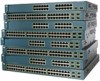
... Setting Up the Switch See the Catalyst 3560 Switch Getting Started Guide for examples of the Catalyst 3560 switch. Features The 24- See the switch software configuration guide for instructions on setting up your Catalyst switch. OL-6337-07 Catalyst 3560 Switch Hardware Installation Guide 1-1 For...to use Express Setup to the switches. The Catalyst 3560-8PC and the Catalyst 3560-12PC-S compact switches provide the same Power over Ethernet (PoE) connectivity and can connect devices like workstations, Cisco Wireless Access Points, Cisco IP Phones, and other network devices such ...
... Setting Up the Switch See the Catalyst 3560 Switch Getting Started Guide for examples of the Catalyst 3560 switch. Features The 24- See the switch software configuration guide for instructions on setting up your Catalyst switch. OL-6337-07 Catalyst 3560 Switch Hardware Installation Guide 1-1 For...to use Express Setup to the switches. The Catalyst 3560-8PC and the Catalyst 3560-12PC-S compact switches provide the same Power over Ethernet (PoE) connectivity and can connect devices like workstations, Cisco Wireless Access Points, Cisco IP Phones, and other network devices such ...

Hardware Installation Guide
Page 12
...; 1000BASE-LX • 1000BASE-SX • 1000BASE-T (only Catalyst 3560 24- and 12-port switches) • 100BASE-FX • 100BASE-LX (only Catalyst 3560 8- and 48-port switches) • 1000BASE-ZX • Coarse Wavelength-Division Multiplexing (CWDM) • SFP module patch cable. (CAB-SFP-50CM=.) Switches running Cisco IOS Release 12.2(25)SEB or later support...
...; 1000BASE-LX • 1000BASE-SX • 1000BASE-T (only Catalyst 3560 24- and 12-port switches) • 100BASE-FX • 100BASE-LX (only Catalyst 3560 8- and 48-port switches) • 1000BASE-ZX • Coarse Wavelength-Division Multiplexing (CWDM) • SFP module patch cable. (CAB-SFP-50CM=.) Switches running Cisco IOS Release 12.2(25)SEB or later support...

Hardware Installation Guide
Page 13
...on page 1-3 • Catalyst 3560-24TS-S, 3560V2-24TS, and 3560V2-24TS-SD Switch Front Panel, Figure 1-2 on page 1-4 • Catalyst 3560-48PS and 3560V2-48PS Switch Front Panel, Figure 1-3 on page 1-4 • Catalyst 3560-48TS-S and 3560V2-48TS Switch Front Panel, Figure 1-4 on page 1-5 • Catalyst 3560-8PC Switch Front Panel, ...11X 2X 12X 13 14 13X 15 16 17 18 19 20 21 22 23 24 Catalyst 3560 SERIES PoE-24 23X 14X 24X 1 2 1 2 1 10/100 PoE ports 2 SFP module slots Catalyst 3560 Switch Hardware Installation Guide 1-3 The first member of the pair (port 1) is above...
...on page 1-3 • Catalyst 3560-24TS-S, 3560V2-24TS, and 3560V2-24TS-SD Switch Front Panel, Figure 1-2 on page 1-4 • Catalyst 3560-48PS and 3560V2-48PS Switch Front Panel, Figure 1-3 on page 1-4 • Catalyst 3560-48TS-S and 3560V2-48TS Switch Front Panel, Figure 1-4 on page 1-5 • Catalyst 3560-8PC Switch Front Panel, ...11X 2X 12X 13 14 13X 15 16 17 18 19 20 21 22 23 24 Catalyst 3560 SERIES PoE-24 23X 14X 24X 1 2 1 2 1 10/100 PoE ports 2 SFP module slots Catalyst 3560 Switch Hardware Installation Guide 1-3 The first member of the pair (port 1) is above...

Hardware Installation Guide
Page 14
... left , as shown in Figure 1-3. Front Panel Description Chapter 1 Product Overview The 10/100 ports on the switch are grouped in pairs. Figure 1-2 Catalyst 3560-24TS-S, 3560V2-24TS, and 3560V2-24TS-SD Switch Front Panel 126808 SYST RPS STAT DUPLX SPEED MODE 12 1X 34 56 78 9 10 11 12 11X 2X 12X 13 14... 13X 15 16 17 18 19 20 21 22 23 24 23X Catalyst 3560 SERIES 14X 24X 1 2 1 2 1 10/100 ports 2 SFP module slots The 10/100 PoE...
... left , as shown in Figure 1-3. Front Panel Description Chapter 1 Product Overview The 10/100 ports on the switch are grouped in pairs. Figure 1-2 Catalyst 3560-24TS-S, 3560V2-24TS, and 3560V2-24TS-SD Switch Front Panel 126808 SYST RPS STAT DUPLX SPEED MODE 12 1X 34 56 78 9 10 11 12 11X 2X 12X 13 14... 13X 15 16 17 18 19 20 21 22 23 24 23X Catalyst 3560 SERIES 14X 24X 1 2 1 2 1 10/100 ports 2 SFP module slots The 10/100 PoE...

Hardware Installation Guide
Page 15
... 1-4 Catalyst 3560-48TS-S and 3560V2-48TS Switch Front Panel 126807 SYST RPS STAT DUPLX SPEED MODE 1 1X 2X 23 45 67 8 9 10 11 12 13 14 15 16 17 15X 17X 18 19 20 21 22 23 24 25 26... 27 28 29 30 31 32 16X 18X 33 31X 33X 34 35 36 37 38 39 40 41 42 43 44 45 46 47 48 47X 32X 34X Catalyst 3560 SERIES 1 3 48X 2 4...45 connector or an SFP module, but not both at the same time. The first member of the Catalyst 3560-8PC switch and the Catalyst 3560-12PC-S switch (Figure 1-5 and Figure 1-6). Port 3 is above port 4, and so on. For ...
... 1-4 Catalyst 3560-48TS-S and 3560V2-48TS Switch Front Panel 126807 SYST RPS STAT DUPLX SPEED MODE 1 1X 2X 23 45 67 8 9 10 11 12 13 14 15 16 17 15X 17X 18 19 20 21 22 23 24 25 26... 27 28 29 30 31 32 16X 18X 33 31X 33X 34 35 36 37 38 39 40 41 42 43 44 45 46 47 48 47X 32X 34X Catalyst 3560 SERIES 1 3 48X 2 4...45 connector or an SFP module, but not both at the same time. The first member of the Catalyst 3560-8PC switch and the Catalyst 3560-12PC-S switch (Figure 1-5 and Figure 1-6). Port 3 is above port 4, and so on. For ...

Hardware Installation Guide
Page 16
... 12X 13 14 13X 15 16 17 18 19 20 21 22 23 24 Catalyst 3560G SERIES PoE-24 23X 25 14X 27 24X 26 28 1 2 1 10/100/1000 ports 2 SFP module slots Catalyst 3560 Switch Hardware Installation Guide 1-6 OL-6337-07 The first member of the pair... 10 11 12 1 2 Catalyst 3560 SERIESPoE-12 1 3 1 Console port 2 10/100 PoE ports 3 Dual-purpose port Gigabit Ethernet Switch Front Panel Descriptions • Catalyst 3560G-24PS Switch Front Panel, Figure 1-7 on page 1-6 • Catalyst 3560G-24TS Switch Front Panel, Figure 1-8 on page 1-7 • Catalyst 3560G-48PS Switch Front Panel, ...
... 12X 13 14 13X 15 16 17 18 19 20 21 22 23 24 Catalyst 3560G SERIES PoE-24 23X 25 14X 27 24X 26 28 1 2 1 10/100/1000 ports 2 SFP module slots Catalyst 3560 Switch Hardware Installation Guide 1-6 OL-6337-07 The first member of the pair... 10 11 12 1 2 Catalyst 3560 SERIESPoE-12 1 3 1 Console port 2 10/100 PoE ports 3 Dual-purpose port Gigabit Ethernet Switch Front Panel Descriptions • Catalyst 3560G-24PS Switch Front Panel, Figure 1-7 on page 1-6 • Catalyst 3560G-24TS Switch Front Panel, Figure 1-8 on page 1-7 • Catalyst 3560G-48PS Switch Front Panel, ...

Hardware Installation Guide
Page 17
... 12X 13 14 13X 15 16 17 18 19 20 21 22 23 24 23X Catalyst 3560G SERIES 25 14X 27 24X 26 28 1 2 1 10/100/1000 ports 2 SFP module slots The 10/100/1000 PoE ports on the Catalyst 3560-24TS switch are grouped in pairs. Port 3 is above port 4, and so on . Port... 3 is above port 4, and so on . The SFP module slots are numbered 25 to 52. Chapter 1 Product Overview Front Panel Description The 10/100/1000 ports on the Catalyst 3560G-48PS switch are...
... 12X 13 14 13X 15 16 17 18 19 20 21 22 23 24 23X Catalyst 3560G SERIES 25 14X 27 24X 26 28 1 2 1 10/100/1000 ports 2 SFP module slots The 10/100/1000 PoE ports on the Catalyst 3560-24TS switch are grouped in pairs. Port 3 is above port 4, and so on . Port... 3 is above port 4, and so on . The SFP module slots are numbered 25 to 52. Chapter 1 Product Overview Front Panel Description The 10/100/1000 ports on the Catalyst 3560G-48PS switch are...

Hardware Installation Guide
Page 18
...who are authorized within 328 feet (100 meters). Front Panel Description Chapter 1 Product Overview The 10/100/1000 ports on the Catalyst 3560G-48TS switch are grouped in Figure 1-10. In all cases, the attached device must be accessed only through the use... 23 45 67 8 9 10 11 12 13 14 15 16 17 15X 17X 18 19 20 21 22 23 24 25 26 27 28 29 30 31 32 16X 18X 33 31X 33X 34 35 36 37 38 39 40 41 ... attached device supports it) and configures itself accordingly. You cannot configure half-duplex mode on . Catalyst 3560 Switch Hardware Installation Guide 1-8 OL-6337-07
...who are authorized within 328 feet (100 meters). Front Panel Description Chapter 1 Product Overview The 10/100/1000 ports on the Catalyst 3560G-48TS switch are grouped in Figure 1-10. In all cases, the attached device must be accessed only through the use... 23 45 67 8 9 10 11 12 13 14 15 16 17 15X 17X 18 19 20 21 22 23 24 25 26 27 28 29 30 31 32 16X 18X 33 31X 33X 34 35 36 37 38 39 40 41 ... attached device supports it) and configures itself accordingly. You cannot configure half-duplex mode on . Catalyst 3560 Switch Hardware Installation Guide 1-8 OL-6337-07

Hardware Installation Guide
Page 19
... primary power source when connected to 15.4 W of approximately 125 W total PoE power. • On a per-port basis, you can connect a Cisco IP Phone or Cisco Aironet Access Point to a Catalyst 3560 PoE switch 10/100 or 10/100/1000 port and to an AC power source for the powered device. When the feature... is the default. - On the Catalyst 3560-48PS, 3560G-48PS, and 3560V2-48PS switches, any 24 of the 48 10/100 or 10/100/1000...
... primary power source when connected to 15.4 W of approximately 125 W total PoE power. • On a per-port basis, you can connect a Cisco IP Phone or Cisco Aironet Access Point to a Catalyst 3560 PoE switch 10/100 or 10/100/1000 port and to an AC power source for the powered device. When the feature... is the default. - On the Catalyst 3560-48PS, 3560G-48PS, and 3560V2-48PS switches, any 24 of the 48 10/100 or 10/100/1000...

Hardware Installation Guide
Page 33
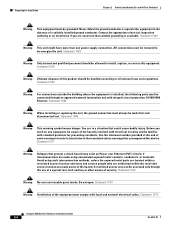
and 12-Port Switches)." and 48-port switches, including how to install the Catalyst 3560 24- For installation information for Installation • Warnings, page 2-2 • Installation Guidelines, page 2-5 • Box Contents, page 2-6 • Tools and Equipment, page 2-6 OL-6337-07 Catalyst 3560 Switch Hardware Installation Guide 2-1 Read the topics and perform the procedures in this order...
and 12-Port Switches)." and 48-port switches, including how to install the Catalyst 3560 24- For installation information for Installation • Warnings, page 2-2 • Installation Guidelines, page 2-5 • Box Contents, page 2-6 • Tools and Equipment, page 2-6 OL-6337-07 Catalyst 3560 Switch Hardware Installation Guide 2-1 Read the topics and perform the procedures in this order...

Hardware Installation Guide
Page 34
...jewelry (including rings, necklaces, and watches). Statement 265 Warning Attach only the following Cisco RPS model to hazardous voltages and currents inside the chassis; Failure to use the... in the Regulatory Compliance and Safety Information for Installation Chapter 2 Switch Installation (24- they direct the flow of clearance around the ventilation openings. Statement 17B Warning...Statement 156 Warning Ethernet cables must be shielded when used in place. Statement 378 Catalyst 3560 Switch Hardware Installation Guide 2-2 OL-6337-07 Statement 48 Warning An exposed wire...
...jewelry (including rings, necklaces, and watches). Statement 265 Warning Attach only the following Cisco RPS model to hazardous voltages and currents inside the chassis; Failure to use the... in the Regulatory Compliance and Safety Information for Installation Chapter 2 Switch Installation (24- they direct the flow of clearance around the ventilation openings. Statement 17B Warning...Statement 156 Warning Ethernet cables must be shielded when used in place. Statement 378 Catalyst 3560 Switch Hardware Installation Guide 2-2 OL-6337-07 Statement 48 Warning An exposed wire...
Hardware Installation Guide
Page 35
...power is removed from the bottom to the top with the heaviest component at the bottom of security. Chapter 2 Switch Installation (24- Statement 1003 Warning Read the installation instructions before mounting or servicing the unit in a partially filled rack, load the rack from ... guidelines are provided to the power source. Statement 1006 Warning Class 1 laser product. Statement 1022 OL-6337-07 Catalyst 3560 Switch Hardware Installation Guide 2-3 Statement 1001 Warning Before performing any of lightning activity. The following procedures, ensure that the system remains ...
...power is removed from the bottom to the top with the heaviest component at the bottom of security. Chapter 2 Switch Installation (24- Statement 1003 Warning Read the installation instructions before mounting or servicing the unit in a partially filled rack, load the rack from ... guidelines are provided to the power source. Statement 1006 Warning Class 1 laser product. Statement 1022 OL-6337-07 Catalyst 3560 Switch Hardware Installation Guide 2-3 Statement 1001 Warning Before performing any of lightning activity. The following procedures, ensure that the system remains ...
Hardware Installation Guide
Page 36
...with local and national electrical codes. All connections must always be familiar with standard practices for Installation Chapter 2 Switch Installation (24- Statement 1046 Warning This warning symbol means danger. You are made using such interconnection methods, unless the exposed metal parts ... in a situation that accompanied this device. Use the statement number provided at the end of the hazard. Statement 1074 Catalyst 3560 Switch Hardware Installation Guide 2-4 OL-6337-07 Statement 1044 Warning When installing or replacing the unit, the ground connection must...
...with local and national electrical codes. All connections must always be familiar with standard practices for Installation Chapter 2 Switch Installation (24- Statement 1046 Warning This warning symbol means danger. You are made using such interconnection methods, unless the exposed metal parts ... in a situation that accompanied this device. Use the statement number provided at the end of the hazard. Statement 1074 Catalyst 3560 Switch Hardware Installation Guide 2-4 OL-6337-07 Statement 1044 Warning When installing or replacing the unit, the ground connection must...

Hardware Installation Guide
Page 37
... does not exceed 113°F (45°C). OL-6337-07 Catalyst 3560 Switch Hardware Installation Guide 2-5 and 48-Port Switches) Statement 371-Power Cable and AC Adapter Preparing for the Catalyst 3560 switch. Chapter 2 Switch Installation (24- Access to insert an inline optical attenuator in Table B-1 on ... than normal room temperature. • Cabling is unrestricted. • Clearance to front and rear panels meets these conditions: - Catalyst 3560 switch SFP ports use shorter lengths of the switch should be routed and tied to connected devices can easily read the front-panel indicators...
... does not exceed 113°F (45°C). OL-6337-07 Catalyst 3560 Switch Hardware Installation Guide 2-5 and 48-Port Switches) Statement 371-Power Cable and AC Adapter Preparing for the Catalyst 3560 switch. Chapter 2 Switch Installation (24- Access to insert an inline optical attenuator in Table B-1 on ... than normal room temperature. • Cabling is unrestricted. • Clearance to front and rear panels meets these conditions: - Catalyst 3560 switch SFP ports use shorter lengths of the switch should be routed and tied to connected devices can easily read the front-panel indicators...
Hardware Installation Guide
Page 38
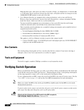
...these fans and blowers can draw dust and other end of suspended particulate matter: - See the "Cisco RPS" section on Cisco.com describes the box contents. Verifying Switch Operation Chapter 2 Switch Installation (24- Network Equipment Building Systems (NEBS) GR-63-CORE - National Electrical Manufacturers Association (NEMA) Type ... Express Setup," in the getting started guide for this equipment in a system malfunction. Warning Attach only the following Cisco RPS model to run Express Setup. Statement 370 Catalyst 3560 Switch Hardware Installation Guide 2-6 OL-6337-07
...these fans and blowers can draw dust and other end of suspended particulate matter: - See the "Cisco RPS" section on Cisco.com describes the box contents. Verifying Switch Operation Chapter 2 Switch Installation (24- Network Equipment Building Systems (NEBS) GR-63-CORE - National Electrical Manufacturers Association (NEMA) Type ... Express Setup," in the getting started guide for this equipment in a system malfunction. Warning Attach only the following Cisco RPS model to run Express Setup. Statement 370 Catalyst 3560 Switch Hardware Installation Guide 2-6 OL-6337-07
Hardware Installation Guide
Page 39
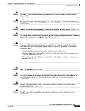
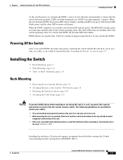
...24- LEDs can blink during the test. The other LEDs remain solid green. Call Cisco technical support representative if your safety: • This unit should be mounted at the bottom of tests that runs automatically to ensure that the system remains stable. or Shelf- OL-6337-07 Catalyst 3560... lasts approximately 1 minute. Mounting, page 2-15 Rack-Mounting • Removing Screws from the Switch, page 2-8 • Attaching Brackets to the Catalyst 3560 Switch, page 2-8 • Mounting the Switch in a Rack, page 2-10 • Attaching the Cable Guide, page 2-11 Warning To prevent...
...24- LEDs can blink during the test. The other LEDs remain solid green. Call Cisco technical support representative if your safety: • This unit should be mounted at the bottom of tests that runs automatically to ensure that the system remains stable. or Shelf- OL-6337-07 Catalyst 3560... lasts approximately 1 minute. Mounting, page 2-15 Rack-Mounting • Removing Screws from the Switch, page 2-8 • Attaching Brackets to the Catalyst 3560 Switch, page 2-8 • Mounting the Switch in a Rack, page 2-10 • Attaching the Cable Guide, page 2-11 Warning To prevent...

Hardware Installation Guide
Page 40
...rack, remove the switch chassis screws (see Figure 2-1.) Figure 2-1 Removing Screws from the Catalyst 3560 Switch 97916 40 41 42 43 44 45 46 47 48 47X Catalyst 3560 SERIES PoE-48 1 3 48X 2 4 Attaching Brackets to a Catalyst 3560 Switch, Front Panel Forward SYST RPS STAT DUPLX SPEED PoE MODE 1 1X 23 45...6337-07 Figure 2-2 1 Attaching Brackets for 19-Inch Racks to the Catalyst 3560 Switch The bracket orientation and the brackets that you use depend on whether you are attaching the brackets for a 19-inch or a 24-inch rack. • For 19-inch racks, use bracket part number...
...rack, remove the switch chassis screws (see Figure 2-1.) Figure 2-1 Removing Screws from the Catalyst 3560 Switch 97916 40 41 42 43 44 45 46 47 48 47X Catalyst 3560 SERIES PoE-48 1 3 48X 2 4 Attaching Brackets to a Catalyst 3560 Switch, Front Panel Forward SYST RPS STAT DUPLX SPEED PoE MODE 1 1X 23 45...6337-07 Figure 2-2 1 Attaching Brackets for 19-Inch Racks to the Catalyst 3560 Switch The bracket orientation and the brackets that you use depend on whether you are attaching the brackets for a 19-inch or a 24-inch rack. • For 19-inch racks, use bracket part number...

Hardware Installation Guide
Page 41
and 48-Port Switches) Installing the Switch Figure 2-3 1 Attaching Brackets for 24-Inch Racks to a Catalyst 3560 Switch, Front Panel Forward 1 Phillips flat-head screws SYST RPS STAT DUPLX SPEED PoE MODE 1 1X 23 45 67 8 9... 5.0A1-20R.05A-A2T,0IN500GV-6~0 HZ [email protected]@YMUO7A.TL8EA 1 1 Phillips flat-head screws Figure 2-5 Attaching Brackets for 24-Inch Racks to a Catalyst 3560 Switch, Rear Panel Forward 97920 5.0A1-20R.05A-A2T,0IN500GV-6~0 HZ [email protected]@YMUO7A.TL8EA 1 1 Phillips flat-head screws...
and 48-Port Switches) Installing the Switch Figure 2-3 1 Attaching Brackets for 24-Inch Racks to a Catalyst 3560 Switch, Front Panel Forward 1 Phillips flat-head screws SYST RPS STAT DUPLX SPEED PoE MODE 1 1X 23 45 67 8 9... 5.0A1-20R.05A-A2T,0IN500GV-6~0 HZ [email protected]@YMUO7A.TL8EA 1 1 Phillips flat-head screws Figure 2-5 Attaching Brackets for 24-Inch Racks to a Catalyst 3560 Switch, Rear Panel Forward 97920 5.0A1-20R.05A-A2T,0IN500GV-6~0 HZ [email protected]@YMUO7A.TL8EA 1 1 Phillips flat-head screws...

Hardware Installation Guide
Page 42
...Attaching Brackets for 19-Inch Telco Racks to a Catalyst 3560 Switch 97921 40 41 42 43 44 45 46 47 48 47X Catalyst 3560 SERIES PoE-48 1 3 48X 2 4 1 1 Phillips flat-head screws Figure 2-7 Attaching Brackets for 24-Inch Telco Racks to a Catalyst 3560 Switch 97922 40 41 42 43 44 45 46... 47 48 47X Catalyst 3560 SERIES PoE-48 1 3 48X 2 1 4 1 ...
...Attaching Brackets for 19-Inch Telco Racks to a Catalyst 3560 Switch 97921 40 41 42 43 44 45 46 47 48 47X Catalyst 3560 SERIES PoE-48 1 3 48X 2 4 1 1 Phillips flat-head screws Figure 2-7 Attaching Brackets for 24-Inch Telco Racks to a Catalyst 3560 Switch 97922 40 41 42 43 44 45 46... 47 48 47X Catalyst 3560 SERIES PoE-48 1 3 48X 2 1 4 1 ...

