

Hardware Installation Guide
Page 2
..., Cisco Explorer, Cisco HealthPresence, Cisco IronPort, the Cisco logo, Cisco Nurse Connect, Cisco Pulse, Cisco SensorBase, Cisco StackPower, Cisco StadiumVision, Cisco TelePresence, Cisco TrustSec, Cisco Unified Computing System, Cisco WebEx, DCE, Flip Channels, Flip for a Class A digital device, pursuant to radio communications. The use of Class B devices: The equipment described in this product not authorized by FCC regulations, and you may cause interference with the specifications in a particular installation. Catalyst 3560 Switch Hardware Installation Guide...
..., Cisco Explorer, Cisco HealthPresence, Cisco IronPort, the Cisco logo, Cisco Nurse Connect, Cisco Pulse, Cisco SensorBase, Cisco StackPower, Cisco StadiumVision, Cisco TelePresence, Cisco TrustSec, Cisco Unified Computing System, Cisco WebEx, DCE, Flip Channels, Flip for a Class A digital device, pursuant to radio communications. The use of Class B devices: The equipment described in this product not authorized by FCC regulations, and you may cause interference with the specifications in a particular installation. Catalyst 3560 Switch Hardware Installation Guide...

Hardware Installation Guide
Page 11
... command-line interface (CLI), see Appendix D, "Configuring the Switch with the CLI-Based Setup Program." This chapter provides a functional overview of how you can be deployed outside the traditional wiring closet environment, such as backbone switches, aggregating 10BASE-T and 100BASE-TX Ethernet traffic from other switches. These topics are hot-swappable. and 48-port Catalyst 3560 switches can connect devices like workstations, Cisco Wireless Access Points, Cisco IP Phones, and other network devices such as servers, routers...
... command-line interface (CLI), see Appendix D, "Configuring the Switch with the CLI-Based Setup Program." This chapter provides a functional overview of how you can be deployed outside the traditional wiring closet environment, such as backbone switches, aggregating 10BASE-T and 100BASE-TX Ethernet traffic from other switches. These topics are hot-swappable. and 48-port Catalyst 3560 switches can connect devices like workstations, Cisco Wireless Access Points, Cisco IP Phones, and other network devices such as servers, routers...

Hardware Installation Guide
Page 18
... and 1000BASE-T traffic requires Category 5 cable. 10BASE-T traffic can set both devices support and full-duplex transmission if the attached device supports it) and configures itself accordingly. Front Panel Description Chapter 1 Product Overview The 10/100/1000 ports on the Catalyst 3560G-48TS switch are grouped in Figure 1-10. Port 3 is above the second member (port 2) on Gigabit Ethernet interfaces if the interface speed is 1000 Mb/s. • When set the 10...
... and 1000BASE-T traffic requires Category 5 cable. 10BASE-T traffic can set both devices support and full-duplex transmission if the attached device supports it) and configures itself accordingly. Front Panel Description Chapter 1 Product Overview The 10/100/1000 ports on the Catalyst 3560G-48TS switch are grouped in Figure 1-10. Port 3 is above the second member (port 2) on Gigabit Ethernet interfaces if the interface speed is 1000 Mb/s. • When set the 10...

Hardware Installation Guide
Page 19
... mdix auto interface configuration command to the powered device. For releases between Cisco IOS Release 12.1(14)EA1 and 12.2(18)SE, the auto-MDIX feature is the default. - The device manager, Network Assistant, and the CLI provide PoE settings for the cables are described in Appendix B, "Connector and Cable Specifications." • You can control whether or not a PoE port automatically provides power when an IP phone or an access point is enabled, the switch detects the required cable type...
... mdix auto interface configuration command to the powered device. For releases between Cisco IOS Release 12.1(14)EA1 and 12.2(18)SE, the auto-MDIX feature is the default. - The device manager, Network Assistant, and the CLI provide PoE settings for the cables are described in Appendix B, "Connector and Cable Specifications." • You can control whether or not a PoE port automatically provides power when an IP phone or an access point is enabled, the switch detects the required cable type...
Hardware Installation Guide
Page 20
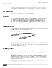
... the "SFP Module Cable Specifications" section on page 2-18 for more information about using the SFP module patch cable. Front Panel Description Chapter 1 Product Overview Many legacy powered devices, including older Cisco IP phones and access points that first links up. Use a Category 5 cable with SFP module connectors at a time. By default, the switch dynamically selects the interface type that do not fully support IEEE 802.3af, might not support PoE when connected to a fiber-optic SFP module. One shows the status of...
... the "SFP Module Cable Specifications" section on page 2-18 for more information about using the SFP module patch cable. Front Panel Description Chapter 1 Product Overview Many legacy powered devices, including older Cisco IP phones and access points that first links up. Use a Category 5 cable with SFP module connectors at a time. By default, the switch dynamically selects the interface type that do not fully support IEEE 802.3af, might not support PoE when connected to a fiber-optic SFP module. One shows the status of...

Hardware Installation Guide
Page 31
... Switch Command Reference on Cisco.com for more information. For setup instructions that use the switch to view switch status and performance information. The CiscoView application, which you can use to set of network configuration concepts. OL-6337-07 Catalyst 3560 Switch Hardware Installation Guide 1-21 See the CiscoView documentation for more information. • SNMP network management You can fully configure and monitor the switch and switch cluster members from a remote management station. The switch supports a comprehensive set configuration parameters and to create...
... Switch Command Reference on Cisco.com for more information. For setup instructions that use the switch to view switch status and performance information. The CiscoView application, which you can use to set of network configuration concepts. OL-6337-07 Catalyst 3560 Switch Hardware Installation Guide 1-21 See the CiscoView documentation for more information. • SNMP network management You can fully configure and monitor the switch and switch cluster members from a remote management station. The switch supports a comprehensive set configuration parameters and to create...

Hardware Installation Guide
Page 34
... the back of electricity. Statement 156 Warning Ethernet cables must be shielded when used in an area that is not connected to follow the correct procedures could result in the Regulatory Compliance and Safety Information for Installation Chapter 2 Switch Installation (24- Statement 265 Warning Attach only the following Cisco RPS model to power lines, remove jewelry (including rings, necklaces, and watches). Warning...
... the back of electricity. Statement 156 Warning Ethernet cables must be shielded when used in an area that is not connected to follow the correct procedures could result in the Regulatory Compliance and Safety Information for Installation Chapter 2 Switch Installation (24- Statement 265 Warning Attach only the following Cisco RPS model to power lines, remove jewelry (including rings, necklaces, and watches). Warning...
Hardware Installation Guide
Page 36
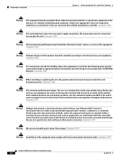
... a situation that accompanied this device. Statement 1072 Warning No user-serviceable parts inside. Do not open. Statement 1074 Catalyst 3560 Switch Hardware Installation Guide 2-4 OL-6337-07 Statement 1046 Warning This warning symbol means danger. Use the statement number provided at the end of security. and 48-Port Switches) Warning This equipment must be allowed to install, replace, or service this product should be removed to de-energize the...
... a situation that accompanied this device. Statement 1072 Warning No user-serviceable parts inside. Do not open. Statement 1074 Catalyst 3560 Switch Hardware Installation Guide 2-4 OL-6337-07 Statement 1046 Warning This warning symbol means danger. Use the statement number provided at the end of security. and 48-Port Switches) Warning This equipment must be allowed to install, replace, or service this product should be removed to de-energize the...
Hardware Installation Guide
Page 38
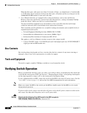
... Cisco Ethernet switches except for the steps required to connect a PC to the switch and to an AC power outlet. See Section 3, "Running Express Setup," in the getting started guide for this equipment in standby mode. Verifying Switch Operation Chapter 2 Switch Installation (24- and 48-Port Switches) When the fiber-optic cable span is missing or damaged, contact your configuration has an RPS, connect the switch and the RPS to rack-mount the switch...
... Cisco Ethernet switches except for the steps required to connect a PC to the switch and to an AC power outlet. See Section 3, "Running Express Setup," in the getting started guide for this equipment in standby mode. Verifying Switch Operation Chapter 2 Switch Installation (24- and 48-Port Switches) When the fiber-optic cable span is missing or damaged, contact your configuration has an RPS, connect the switch and the RPS to rack-mount the switch...

Hardware Installation Guide
Page 51
... connect Cisco prestandard IP Phones or wireless access points or IEEE 802.3af-compliant devices to 10 or 100 Mb/s. If the attached ports do not autonegotiate or that causes a PoE fault from the network. The default setting is enabled, the switch detects the required cable type for this feature, see the switch software configuration guide or the switch command reference. When the auto-MDIX feature is Auto. The auto-MDIX feature is disabled by default on Power over Ethernet (PoE...
... connect Cisco prestandard IP Phones or wireless access points or IEEE 802.3af-compliant devices to 10 or 100 Mb/s. If the attached ports do not autonegotiate or that causes a PoE fault from the network. The default setting is enabled, the switch detects the required cable type for this feature, see the switch software configuration guide or the switch command reference. When the auto-MDIX feature is Auto. The auto-MDIX feature is disabled by default on Power over Ethernet (PoE...

Hardware Installation Guide
Page 58
... 17B Warning Before working on any other equipment; Statement 378 Catalyst 3560 Switch Hardware Installation Guide 3-2 OL-6337-07 and 12-Port Switches) Warnings These warnings are in a hazardous situation to people and damage to power lines, remove jewelry (including rings, necklaces, and watches). If the chassis falls, it in a central office environment. Statement 156 Warning Ethernet cables must be shielded when used in an...
... 17B Warning Before working on any other equipment; Statement 378 Catalyst 3560 Switch Hardware Installation Guide 3-2 OL-6337-07 and 12-Port Switches) Warnings These warnings are in a hazardous situation to people and damage to power lines, remove jewelry (including rings, necklaces, and watches). If the chassis falls, it in a central office environment. Statement 156 Warning Ethernet cables must be shielded when used in an...
Hardware Installation Guide
Page 72
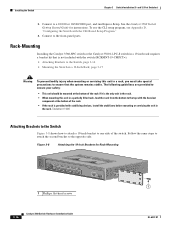
... Switch Getting Started Guide for Rack-Mounting SYST STAT DPLX SPD PoE MODE CONSOLE 1x 2x 3x 4x 5x 6x 7x 8x Catalyst 3560 SERIES PoE-8 1 1 1 Phillips flat-head screws 3-16 Catalyst 3560 Switch Hardware Installation Guide OL-6337-07 Connect to the opposite side. Statement 1006 Attaching Brackets to the Switch Figure 3-8 shows how to attach a 19-inch bracket to the top with stabilizing devices, install the stabilizers before mounting or servicing...
... Switch Getting Started Guide for Rack-Mounting SYST STAT DPLX SPD PoE MODE CONSOLE 1x 2x 3x 4x 5x 6x 7x 8x Catalyst 3560 SERIES PoE-8 1 1 1 Phillips flat-head screws 3-16 Catalyst 3560 Switch Hardware Installation Guide OL-6337-07 Connect to the opposite side. Statement 1006 Attaching Brackets to the Switch Figure 3-8 shows how to attach a 19-inch bracket to the top with stabilizing devices, install the stabilizers before mounting or servicing...
Hardware Installation Guide
Page 77
... the Switch Serial Number, page 4-6 Diagnosing Problems The LEDs on the front panel provide troubleshooting information about the switch. See the software configuration guide and the switch command reference on Cisco.com or the documentation that came with your SNMP application for more information. • Evaluate Switch POST Results, page 4-2 • Monitor Switch LEDs, page 4-2 • Verify Switch Connections, page 4-2 • Monitor Switch Performance, page 4-4 OL-6337-07 Catalyst 3560 Switch Hardware Installation Guide 4-1 They show POST failures, port-connectivity...
... the Switch Serial Number, page 4-6 Diagnosing Problems The LEDs on the front panel provide troubleshooting information about the switch. See the software configuration guide and the switch command reference on Cisco.com or the documentation that came with your SNMP application for more information. • Evaluate Switch POST Results, page 4-2 • Monitor Switch LEDs, page 4-2 • Verify Switch Connections, page 4-2 • Monitor Switch Performance, page 4-4 OL-6337-07 Catalyst 3560 Switch Hardware Installation Guide 4-1 They show POST failures, port-connectivity...

Hardware Installation Guide
Page 79
... both ends of supported SFP modules. • Use the show link, but is not. Verify that both devices have power. • Verify that you are connected to a known, good device. • Make sure that this module supports this platform. Disconnect and then reconnect the cable. Look for 10 Mb/s unshielded twisted pair (UTP) connections. OL-6337-07 Catalyst 3560 Switch Hardware Installation Guide 4-3 Chapter 4 Troubleshooting Diagnosing Problems Ethernet and Fiber Cables Make sure...
... both ends of supported SFP modules. • Use the show link, but is not. Verify that both devices have power. • Verify that you are connected to a known, good device. • Make sure that this module supports this platform. Disconnect and then reconnect the cable. Look for 10 Mb/s unshielded twisted pair (UTP) connections. OL-6337-07 Catalyst 3560 Switch Hardware Installation Guide 4-3 Chapter 4 Troubleshooting Diagnosing Problems Ethernet and Fiber Cables Make sure...

Hardware Installation Guide
Page 80
... legitimate traffic. Monitor Switch Performance Review these sections when you find unidirectional link problems. UDLD supports a normal mode of the link, the link does not come up until you troubleshoot switch performance problems: • Speed, Duplex, and Autonegotiation, page 4-4 • Autonegotiation and Network Interface Cards, page 4-5 • Cabling Distance, page 4-5 Speed, Duplex, and Autonegotiation If the port statistics show interfaces privileged EXEC command to verify the port or interface error-disabled, disabled, or shutdown status on fiber-optic connections...
... legitimate traffic. Monitor Switch Performance Review these sections when you find unidirectional link problems. UDLD supports a normal mode of the link, the link does not come up until you troubleshoot switch performance problems: • Speed, Duplex, and Autonegotiation, page 4-4 • Autonegotiation and Network Interface Cards, page 4-5 • Cabling Distance, page 4-5 Speed, Duplex, and Autonegotiation If the port statistics show interfaces privileged EXEC command to verify the port or interface error-disabled, disabled, or shutdown status on fiber-optic connections...

Hardware Installation Guide
Page 81
... the factory default settings: 1. Cabling Distance If the port statistics show excessive FCS, late-collision, or alignment errors, verify that is not configured, the LEDs above the Mode button turn green. Press and hold the Mode button. To maximize switch performance and to ensure a link, follow this does not solve the problem, the firmware or software on the two ports to configure the switch. 2. Do not follow one of the connection. • If a remote device...
... the factory default settings: 1. Cabling Distance If the port statistics show excessive FCS, late-collision, or alignment errors, verify that is not configured, the LEDs above the Mode button turn green. Press and hold the Mode button. To maximize switch performance and to ensure a link, follow this does not solve the problem, the firmware or software on the two ports to configure the switch. 2. Do not follow one of the connection. • If a remote device...
Hardware Installation Guide
Page 111
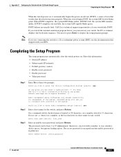
...) • Default gateway (router) • Enable secret password • Enable password • Telnet password Step 1 Enter Yes at any switch. on . Completing the Setup Program The setup program runs automatically after the switch powers on a member switch to 31 characters. for management of tests that verifies that shipped with your switch fails POST. If POST fails, the system LED remains amber. When POST completes, the system LED blinks amber. Appendix D Configuring the Switch with the CLI-Based Setup Program...
...) • Default gateway (router) • Enable secret password • Enable password • Telnet password Step 1 Enter Yes at any switch. on . Completing the Setup Program The setup program runs automatically after the switch powers on a member switch to 31 characters. for management of tests that verifies that shipped with your switch fails POST. If POST fails, the system LED remains amber. When POST completes, the system LED blinks amber. Appendix D Configuring the Switch with the CLI-Based Setup Program...

Hardware Installation Guide
Page 113
... [2]:2 Make your switch, connecting to the switch ports, or connecting to save it the next time the switch reboots, save the configuration and use CMS, see the Getting Started with the CLI-Based Setup Program Completing the Setup Program ! OL-6337-07 Catalyst 3560 Switch Hardware Installation Guide D-5 If you want to change this configuration to perform other management tasks, use one of these tools: • Command-line interface (CLI) • CMS from your browser • Network Assistant from...
... [2]:2 Make your switch, connecting to the switch ports, or connecting to save it the next time the switch reboots, save the configuration and use CMS, see the Getting Started with the CLI-Based Setup Program Completing the Setup Program ! OL-6337-07 Catalyst 3560 Switch Hardware Installation Guide D-5 If you want to change this configuration to perform other management tasks, use one of these tools: • Command-line interface (CLI) • CMS from your browser • Network Assistant from...

Hardware Installation Guide
Page 116
Index torquing recommendation C-6 Cisco IOS command-line interface 1-21 Cisco IP Phones, connecting to 1-9, 2-20 Cisco Network Assistant 1-20 Cisco RPS See RPS CiscoView 1-21 CLI to manage switch 1-21 to set up switch D-1 code compliance warning 2-4, 3-4 command-line interface See CLI configuration examples, network 1-1 connecting to 10/100/1000 ports 2-19 to 10/100 ports 2-19 to console port B-3 to DC power C-1 to C-2 to SFP modules 2-21 to 2-23 connection procedures 2-19 to 2-23 connectors and cables 10/100 ports B-2 console port B-3 to B-8 dual-purpose ports B-3 power (AC and...
Index torquing recommendation C-6 Cisco IOS command-line interface 1-21 Cisco IP Phones, connecting to 1-9, 2-20 Cisco Network Assistant 1-20 Cisco RPS See RPS CiscoView 1-21 CLI to manage switch 1-21 to set up switch D-1 code compliance warning 2-4, 3-4 command-line interface See CLI configuration examples, network 1-1 connecting to 10/100/1000 ports 2-19 to 10/100 ports 2-19 to console port B-3 to DC power C-1 to C-2 to SFP modules 2-21 to 2-23 connection procedures 2-19 to 2-23 connectors and cables 10/100 ports B-2 console port B-3 to B-8 dual-purpose ports B-3 power (AC and...
Hardware Installation Guide
Page 119
...and 12-port switches 3-16, 3-17 rear panel clearance 2-5, 3-5 description 1-15 to 1-19 removing SFP modules 2-17 to 2-18 restricted access area warning C-1 RJ-45 connector, console port B-3 RPS connecting to 4-6 bad or damaged cable 4-2 connection problems 4-2 diagnosing problems 4-1 Ethernet and fiber-optic cables 4-3 link status 4-3 ping end device 4-4 port and interface settings 4-4 POST 4-1 spanning tree loops 4-4 speed, duplex, and autonegotiation 4-4 switch performance 4-4 troubleshooting spanning tree loops 4-4 W wall-mounting 24- and 48-port switches 2-15 8- and 12-port switches 3-17...
...and 12-port switches 3-16, 3-17 rear panel clearance 2-5, 3-5 description 1-15 to 1-19 removing SFP modules 2-17 to 2-18 restricted access area warning C-1 RJ-45 connector, console port B-3 RPS connecting to 4-6 bad or damaged cable 4-2 connection problems 4-2 diagnosing problems 4-1 Ethernet and fiber-optic cables 4-3 link status 4-3 ping end device 4-4 port and interface settings 4-4 POST 4-1 spanning tree loops 4-4 speed, duplex, and autonegotiation 4-4 switch performance 4-4 troubleshooting spanning tree loops 4-4 W wall-mounting 24- and 48-port switches 2-15 8- and 12-port switches 3-17...


