

Hardware Installation Guide
Page 1
Catalyst 3560 Switch Hardware Installation Guide March 2010 Americas Headquarters Cisco Systems, Inc. 170 West Tasman Drive San Jose, CA 95134-1706 USA http://www.cisco.com Tel: 408 526-4000 800 553-NETS (6387) Fax: 408 527-0883 Text Part Number: OL-6337-07
Catalyst 3560 Switch Hardware Installation Guide March 2010 Americas Headquarters Cisco Systems, Inc. 170 West Tasman Drive San Jose, CA 95134-1706 USA http://www.cisco.com Tel: 408 526-4000 800 553-NETS (6387) Fax: 408 527-0883 Text Part Number: OL-6337-07

Hardware Installation Guide
Page 2
...WebEx logo are not intended to be required to correct any other countries. Catalyst 3560 Switch Hardware Installation Guide © 2004-2010 Cisco Systems, Inc. could void the FCC approval and negate your equipment is not installed ... property of the FCC rules. CCDE, CCENT, CCSI, Cisco Eos, Cisco Explorer, Cisco HealthPresence, Cisco IronPort, the Cisco logo, Cisco Nurse Connect, Cisco Pulse, Cisco SensorBase, Cisco StackPower, Cisco StadiumVision, Cisco TelePresence, Cisco TrustSec, Cisco Unified Computing System, Cisco WebEx, DCE, Flip Channels, Flip for illustrative purposes only...
...WebEx logo are not intended to be required to correct any other countries. Catalyst 3560 Switch Hardware Installation Guide © 2004-2010 Cisco Systems, Inc. could void the FCC approval and negate your equipment is not installed ... property of the FCC rules. CCDE, CCENT, CCSI, Cisco Eos, Cisco Explorer, Cisco HealthPresence, Cisco IronPort, the Cisco logo, Cisco Nurse Connect, Cisco Pulse, Cisco SensorBase, Cisco StackPower, Cisco StadiumVision, Cisco TelePresence, Cisco TrustSec, Cisco Unified Computing System, Cisco WebEx, DCE, Flip Channels, Flip for illustrative purposes only...
Hardware Installation Guide
Page 3
... i-vii Related Publications i-viii Obtaining Documentation and Submitting a Service Request i-ix Product Overview 1-1 Setting Up the Switch 1-1 Features 1-1 Front Panel Description 1-3 Fast Ethernet Switch Front Panel Descriptions 1-3 Gigabit Ethernet Switch Front Panel Descriptions 1-6 10/100 and 10/100/1000 Ports 1-8 PoE Ports 1-9 SFP Module Slots 1-10 ... Port LEDs 1-15 Cable Guard 1-15 Rear Panel Description 1-15 Internal Power Supply 1-18 DC Power Connector 1-18 Cisco RPS 1-19 Cisco RPS 2300 1-19 Cisco RPS 675 1-19 Console Port 1-19 Security Slots 1-20 Management Options 1-20 Catalyst 3560...
... i-vii Related Publications i-viii Obtaining Documentation and Submitting a Service Request i-ix Product Overview 1-1 Setting Up the Switch 1-1 Features 1-1 Front Panel Description 1-3 Fast Ethernet Switch Front Panel Descriptions 1-3 Gigabit Ethernet Switch Front Panel Descriptions 1-6 10/100 and 10/100/1000 Ports 1-8 PoE Ports 1-9 SFP Module Slots 1-10 ... Port LEDs 1-15 Cable Guard 1-15 Rear Panel Description 1-15 Internal Power Supply 1-18 DC Power Connector 1-18 Cisco RPS 1-19 Cisco RPS 2300 1-19 Cisco RPS 675 1-19 Console Port 1-19 Security Slots 1-20 Management Options 1-20 Catalyst 3560...

Hardware Installation Guide
Page 4
...from SFP Module Slots 2-17 Inserting and Removing the SFP Module Patch Cable 2-18 10/100 or 10/100/1000 Ports 2-19 Connecting the Switch to Compatible Devices 2-20 Connecting to 10BASE-T or 100BASE-TX Devices 2-20 Connecting to Fiber-Optic SFP Modules 2-21 Connecting to 1000BASE-T SFP... 2-15 Installing and Removing SFP Modules 2-15 Installing SFP Modules into SFP Module Slots 2-16 Removing SFP Modules from the Switch 2-8 Attaching Brackets to the Catalyst 3560 Switch 2-8 Mounting the Switch in a Rack 2-10 Attaching the Cable Guide 2-11 Wall-Mounting 2-12 Attaching the Brackets to Go Next 2-24...
...from SFP Module Slots 2-17 Inserting and Removing the SFP Module Patch Cable 2-18 10/100 or 10/100/1000 Ports 2-19 Connecting the Switch to Compatible Devices 2-20 Connecting to 10BASE-T or 100BASE-TX Devices 2-20 Connecting to Fiber-Optic SFP Modules 2-21 Connecting to 1000BASE-T SFP... 2-15 Installing and Removing SFP Modules 2-15 Installing SFP Modules into SFP Module Slots 2-16 Removing SFP Modules from the Switch 2-8 Attaching Brackets to the Catalyst 3560 Switch 2-8 Mounting the Switch in a Rack 2-10 Attaching the Cable Guide 2-11 Wall-Mounting 2-12 Attaching the Brackets to Go Next 2-24...

Hardware Installation Guide
Page 5
... or Shelf Mounting 3-9 Wall-Mounting (with Mounting Screws) 3-12 Magnet Mounting 3-15 Rack-Mounting 3-16 Attaching Brackets to the Switch 3-16 Mounting the Switch in a 19-Inch Rack 3-17 Wall-Mounting (with Rack-Mount Brackets) 3-17 Securing the AC Power Cord 3-19 Where ...to Go Next 3-20 Troubleshooting 4-1 Diagnosing Problems 4-1 Evaluate Switch POST Results 4-2 Monitor Switch LEDs 4-2 Verify Switch Connections 4-2 Bad or Damaged Cable 4-2 Ethernet and Fiber Cables 4-3 Link Status 4-3 Transceiver Module Port Issues 4-3 Port and ...
... or Shelf Mounting 3-9 Wall-Mounting (with Mounting Screws) 3-12 Magnet Mounting 3-15 Rack-Mounting 3-16 Attaching Brackets to the Switch 3-16 Mounting the Switch in a 19-Inch Rack 3-17 Wall-Mounting (with Rack-Mount Brackets) 3-17 Securing the AC Power Cord 3-19 Where ...to Go Next 3-20 Troubleshooting 4-1 Diagnosing Problems 4-1 Evaluate Switch POST Results 4-2 Monitor Switch LEDs 4-2 Verify Switch Connections 4-2 Bad or Damaged Cable 4-2 Ethernet and Fiber Cables 4-3 Link Status 4-3 Transceiver Module Port Issues 4-3 Port and ...

Hardware Installation Guide
Page 6
... Twisted-Pair Cable Pinouts for 1000BASE-T Ports B-6 Identifying a Crossover Cable B-6 Adapter Pinouts B-7 Connecting to DC Power C-1 Connecting to DC Power C-1 Preparing for Installation C-2 Grounding the Switch C-2 Wiring the DC-Input Power Source C-5 Configuring the Switch with the CLI-Based Setup Program D-1 Preparing for Setup D-1 Completing the Setup Program D-3 Catalyst 3560...
... Twisted-Pair Cable Pinouts for 1000BASE-T Ports B-6 Identifying a Crossover Cable B-6 Adapter Pinouts B-7 Connecting to DC Power C-1 Connecting to DC Power C-1 Preparing for Installation C-2 Grounding the Switch C-2 Wiring the DC-Input Power Source C-5 Configuring the Switch with the CLI-Based Setup Program D-1 Preparing for Setup D-1 Completing the Setup Program D-3 Catalyst 3560...

Hardware Installation Guide
Page 7
... describes the physical and performance characteristics of the Catalyst 3560 switch. For information about the standard Cisco IOS Release 12.2 commands, see the switch software configuration guide, the switch command reference, and the switch system message guide on the Cisco Training & Events web page: http://www.cisco.com/web/learning/index.html Purpose This guide describes the...
... describes the physical and performance characteristics of the Catalyst 3560 switch. For information about the standard Cisco IOS Release 12.2 commands, see the switch software configuration guide, the switch command reference, and the switch system message guide on the Cisco Training & Events web page: http://www.cisco.com/web/learning/index.html Purpose This guide describes the...

Hardware Installation Guide
Page 8
... accidents. Before you work on the switch) For information about the switch and are available from this Cisco.com site: http://www.cisco.com/en/US/products/hw/modules/ps5455/products_device_support_tables_list.html • Cisco Gigabit Ethernet Transceiver Modules Compatibility Matrix • Cisco 100-Megabit Ethernet SFP Modules Compatibility Matrix • Cisco CWDM SFP Transceiver Compatibility Matrix Catalyst...
... accidents. Before you work on the switch) For information about the switch and are available from this Cisco.com site: http://www.cisco.com/en/US/products/hw/modules/ps5455/products_device_support_tables_list.html • Cisco Gigabit Ethernet Transceiver Modules Compatibility Matrix • Cisco 100-Megabit Ethernet SFP Modules Compatibility Matrix • Cisco CWDM SFP Transceiver Compatibility Matrix Catalyst...

Hardware Installation Guide
Page 9
OL-6337-07 Catalyst 3560 Switch Hardware Installation Guide ix The RSS feeds are a free service and Cisco currently supports RSS version 2.0. Preface Obtaining Documentation and Submitting a Service Request • Cisco Small Form-Factor Pluggable Modules Compatibility Matrix • Compatibility Matrix for ... service request, and gathering additional information, see the monthly What's New in Cisco Product Documentation, which also lists all new and revised Cisco technical documentation, at: http://www.cisco.com/en/US/docs/general/whatsnew/whatsnew.html Subscribe to the What's New ...
OL-6337-07 Catalyst 3560 Switch Hardware Installation Guide ix The RSS feeds are a free service and Cisco currently supports RSS version 2.0. Preface Obtaining Documentation and Submitting a Service Request • Cisco Small Form-Factor Pluggable Modules Compatibility Matrix • Compatibility Matrix for ... service request, and gathering additional information, see the monthly What's New in Cisco Product Documentation, which also lists all new and revised Cisco technical documentation, at: http://www.cisco.com/en/US/docs/general/whatsnew/whatsnew.html Subscribe to the What's New ...

Hardware Installation Guide
Page 10
Obtaining Documentation and Submitting a Service Request Preface Catalyst 3560 Switch Hardware Installation Guide x OL-6337-07
Obtaining Documentation and Submitting a Service Request Preface Catalyst 3560 Switch Hardware Installation Guide x OL-6337-07

Hardware Installation Guide
Page 11
... the traditional wiring closet environment, such as backbone switches, aggregating 10BASE-T and 100BASE-TX Ethernet traffic from other switches. and 12-port switches include connections for examples of the Catalyst 3560 switch. Features The 24- See the switch software configuration guide for an optional Cisco RPS 2300 or Cisco RPS 675 that operates on AC power and...
... the traditional wiring closet environment, such as backbone switches, aggregating 10BASE-T and 100BASE-TX Ethernet traffic from other switches. and 12-port switches include connections for examples of the Catalyst 3560 switch. Features The 24- See the switch software configuration guide for an optional Cisco RPS 2300 or Cisco RPS 675 that operates on AC power and...

Hardware Installation Guide
Page 12
...8226; SFP module patch cable. (CAB-SFP-50CM=.) Switches running Cisco IOS Release 12.2(25)SEB or later support this patch cable. and 12-port switches) • 1000BASE-BX10 • 1000BASE-LX • 1000BASE-SX • 1000BASE-T (only Catalyst 3560 24- Catalyst 3560 Switch Hardware Installation Guide 1-2 OL-6337-07 and 12-port...-24PS 24 10/100 PoE ports and 2 SFP module slots Catalyst 3560V2-24TS 24 10/100 ports and 2 SFP module slots Catalyst 3560V2-48PS 48 10/100 PoE ports and 4 SFP module slots Catalyst 3560V2-48TS 48 10/100 ports and 4 SFP module slots Catalyst 3560V2-24TS-...
...8226; SFP module patch cable. (CAB-SFP-50CM=.) Switches running Cisco IOS Release 12.2(25)SEB or later support this patch cable. and 12-port switches) • 1000BASE-BX10 • 1000BASE-LX • 1000BASE-SX • 1000BASE-T (only Catalyst 3560 24- Catalyst 3560 Switch Hardware Installation Guide 1-2 OL-6337-07 and 12-port...-24PS 24 10/100 PoE ports and 2 SFP module slots Catalyst 3560V2-24TS 24 10/100 ports and 2 SFP module slots Catalyst 3560V2-48PS 48 10/100 PoE ports and 4 SFP module slots Catalyst 3560V2-48TS 48 10/100 ports and 4 SFP module slots Catalyst 3560V2-24TS-...

Hardware Installation Guide
Page 13
... 1-3 • Catalyst 3560-24TS-S, 3560V2-24TS, and 3560V2-24TS-SD Switch Front Panel, Figure 1-2 on page 1-4 • Catalyst 3560-48PS and 3560V2-48PS Switch Front Panel, Figure 1-3 on page 1-4 • Catalyst 3560-48TS-S and 3560V2-48TS Switch Front Panel, Figure 1-4 on page 1-5 • Catalyst 3560-8PC Switch Front Panel, Figure 1-5 on page 1-5 • Catalyst 3560-12PC...
... 1-3 • Catalyst 3560-24TS-S, 3560V2-24TS, and 3560V2-24TS-SD Switch Front Panel, Figure 1-2 on page 1-4 • Catalyst 3560-48PS and 3560V2-48PS Switch Front Panel, Figure 1-3 on page 1-4 • Catalyst 3560-48TS-S and 3560V2-48TS Switch Front Panel, Figure 1-4 on page 1-5 • Catalyst 3560-8PC Switch Front Panel, Figure 1-5 on page 1-5 • Catalyst 3560-12PC...

Hardware Installation Guide
Page 14
...22 23 24 23X Catalyst 3560 SERIES 14X 24X 1 2 1 2 1 10/100 ports 2 SFP module slots The 10/100 PoE ports on . Figure 1-3 Catalyst 3560-48PS and 3560V2-48PS Switch Front Panel 97911 SYST RPS STAT DUPLX SPEED PoE MODE 1 1X 2X 23 45 67 8 9 10 11 12 13 14 15 16 17 15X... the pair (port 1) is above the second member (port 2) on the left , as shown in pairs. Port 3 is above port 4, and so on the switch are grouped in Figure 1-2. Front Panel Description Chapter 1 Product Overview The 10/100 ports on . The first member of the pair (port 1) is above the...
...22 23 24 23X Catalyst 3560 SERIES 14X 24X 1 2 1 2 1 10/100 ports 2 SFP module slots The 10/100 PoE ports on . Figure 1-3 Catalyst 3560-48PS and 3560V2-48PS Switch Front Panel 97911 SYST RPS STAT DUPLX SPEED PoE MODE 1 1X 2X 23 45 67 8 9 10 11 12 13 14 15 16 17 15X... the pair (port 1) is above the second member (port 2) on the left , as shown in pairs. Port 3 is above port 4, and so on the switch are grouped in Figure 1-2. Front Panel Description Chapter 1 Product Overview The 10/100 ports on . The first member of the pair (port 1) is above the...

Hardware Installation Guide
Page 15
...1 to 4. For more information on the dual-purpose port, see the "Console Port" section on page 1-19. Figure 1-5 Catalyst 3560-8PC Switch Front Panel SYST STAT DPLX SPD MODE CONSOLE 1x 2x 3x 4x 5x 6x 7x 8x Catalyst 2960 Series 1 157822 1 2 3 1 Console port... 2 10/100 PoE ports 3 Dual-purpose port OL-6337-07 Catalyst 3560 Switch Hardware Installation Guide 1-5 The first member of the Catalyst 3560-8PC switch and the Catalyst 3560-12PC-S switch (Figure 1-5 and Figure 1-6). Chapter 1 Product Overview Front Panel Description The 10/100 ports on the...
...1 to 4. For more information on the dual-purpose port, see the "Console Port" section on page 1-19. Figure 1-5 Catalyst 3560-8PC Switch Front Panel SYST STAT DPLX SPD MODE CONSOLE 1x 2x 3x 4x 5x 6x 7x 8x Catalyst 2960 Series 1 157822 1 2 3 1 Console port... 2 10/100 PoE ports 3 Dual-purpose port OL-6337-07 Catalyst 3560 Switch Hardware Installation Guide 1-5 The first member of the Catalyst 3560-8PC switch and the Catalyst 3560-12PC-S switch (Figure 1-5 and Figure 1-6). Chapter 1 Product Overview Front Panel Description The 10/100 ports on the...

Hardware Installation Guide
Page 16
... 2 10/100 PoE ports 3 Dual-purpose port Gigabit Ethernet Switch Front Panel Descriptions • Catalyst 3560G-24PS Switch Front Panel, Figure 1-7 on page 1-6 • Catalyst 3560G-24TS Switch Front Panel, Figure 1-8 on page 1-7 • Catalyst 3560G-48PS Switch Front Panel, Figure 1-9 on page 1-7 • Catalyst 3560G-48TS Switch Front Panel, Figure 1-10 on page 1-8 The 10...
... 2 10/100 PoE ports 3 Dual-purpose port Gigabit Ethernet Switch Front Panel Descriptions • Catalyst 3560G-24PS Switch Front Panel, Figure 1-7 on page 1-6 • Catalyst 3560G-24TS Switch Front Panel, Figure 1-8 on page 1-7 • Catalyst 3560G-48PS Switch Front Panel, Figure 1-9 on page 1-7 • Catalyst 3560G-48TS Switch Front Panel, Figure 1-10 on page 1-8 The 10...

Hardware Installation Guide
Page 17
... 3560G SERIES 25 14X 27 24X 26 28 1 2 1 10/100/1000 ports 2 SFP module slots The 10/100/1000 PoE ports on the Catalyst 3560G-48PS switch are numbered 49 to 28. Port 3 is above port 4, and so on. The first member of the pair (port 1) is above the second member (port... in Figure 1-8. The first member of the pair (port 1) is above the second member (port 2) on the left , as shown in pairs. Figure 1-9 Catalyst 3560G-48PS Switch Front Panel 119674 SYST RPS STAT DUPLX SPEED PoE MODE 1 1X 2X 23 45 67 8 9 10 11 12 13 14 15 16 17 15X 17X...
... 3560G SERIES 25 14X 27 24X 26 28 1 2 1 10/100/1000 ports 2 SFP module slots The 10/100/1000 PoE ports on the Catalyst 3560G-48PS switch are numbered 49 to 28. Port 3 is above port 4, and so on. The first member of the pair (port 1) is above the second member (port... in Figure 1-8. The first member of the pair (port 1) is above the second member (port 2) on the left , as shown in pairs. Figure 1-9 Catalyst 3560G-48PS Switch Front Panel 119674 SYST RPS STAT DUPLX SPEED PoE MODE 1 1X 2X 23 45 67 8 9 10 11 12 13 14 15 16 17 15X 17X...

Hardware Installation Guide
Page 18
...100 ports to operate in compliance with IEEE 802.3ab. (The default setting is above port 4, and so on the Catalyst 3560G-48TS switch are made aware of the hazard. Avoid using uninsulated exposed metal contacts, conductors, or terminals. Statement 1072 • 100BASE-TX and 1000BASE... configures itself accordingly. In all cases, the attached device must be accessed only through the use Category 3 or Category 4 cables. Catalyst 3560 Switch Hardware Installation Guide 1-8 OL-6337-07 A restricted access area can use of a special tool, lock and key or other means of the attached...
...100 ports to operate in compliance with IEEE 802.3ab. (The default setting is above port 4, and so on the Catalyst 3560G-48TS switch are made aware of the hazard. Avoid using uninsulated exposed metal contacts, conductors, or terminals. Statement 1072 • 100BASE-TX and 1000BASE... configures itself accordingly. In all cases, the attached device must be accessed only through the use Category 3 or Category 4 cables. Catalyst 3560 Switch Hardware Installation Guide 1-8 OL-6337-07 A restricted access area can use of a special tool, lock and key or other means of the attached...

Hardware Installation Guide
Page 19
... for proper operation. For releases between Cisco IOS Release 12.1(14)EA1 and 12.2(18)SE, the auto-MDIX feature is enabled, the switch detects the required cable type for copper Ethernet connections and configures the interfaces accordingly. On the Catalyst 3560-48PS, 3560G-48PS, and 3560V2-48PS switches, any 24 of the 48 10/100...
... for proper operation. For releases between Cisco IOS Release 12.1(14)EA1 and 12.2(18)SE, the auto-MDIX feature is enabled, the switch detects the required cable type for copper Ethernet connections and configures the interfaces accordingly. On the Catalyst 3560-48PS, 3560G-48PS, and 3560V2-48PS switches, any 24 of the 48 10/100...
Hardware Installation Guide
Page 20
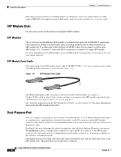
...passive cable with dual front ends-an RJ-45 connector and an SFP module connector. Each port is on page B-4. By default, the switch dynamically selects the interface type that do not fully support IEEE 802.3af, might not support PoE when connected to a fiber-optic SFP ...and 1000BASE-T connections. Front Panel Description Chapter 1 Product Overview Many legacy powered devices, including older Cisco IP phones and access points that first links up. SFP Modules The switch uses Gigabit Ethernet SFP modules to a copper SFP module. For information about configuring speed and duplex...
...passive cable with dual front ends-an RJ-45 connector and an SFP module connector. Each port is on page B-4. By default, the switch dynamically selects the interface type that do not fully support IEEE 802.3af, might not support PoE when connected to a fiber-optic SFP ...and 1000BASE-T connections. Front Panel Description Chapter 1 Product Overview Many legacy powered devices, including older Cisco IP phones and access points that first links up. SFP Modules The switch uses Gigabit Ethernet SFP modules to a copper SFP module. For information about configuring speed and duplex...


