
Hardware Installation Guide
Page 3
... i-vii Related Publications i-viii Obtaining Documentation and Submitting a Service Request i-ix Product Overview 1-1 Setting Up the Switch 1-1 Features 1-1 Front Panel Description 1-3 Fast Ethernet Switch Front Panel Descriptions 1-3 Gigabit Ethernet Switch Front Panel Descriptions 1-6 10/100 and 10/100/1000 Ports 1-8 PoE Ports 1-9 SFP Module Slots 1-10 SFP... 1-15 Cable Guard 1-15 Rear Panel Description 1-15 Internal Power Supply 1-18 DC Power Connector 1-18 Cisco RPS 1-19 Cisco RPS 2300 1-19 Cisco RPS 675 1-19 Console Port 1-19 Security Slots 1-20 Management Options 1-20 Catalyst 3560...
... i-vii Related Publications i-viii Obtaining Documentation and Submitting a Service Request i-ix Product Overview 1-1 Setting Up the Switch 1-1 Features 1-1 Front Panel Description 1-3 Fast Ethernet Switch Front Panel Descriptions 1-3 Gigabit Ethernet Switch Front Panel Descriptions 1-6 10/100 and 10/100/1000 Ports 1-8 PoE Ports 1-9 SFP Module Slots 1-10 SFP... 1-15 Cable Guard 1-15 Rear Panel Description 1-15 Internal Power Supply 1-18 DC Power Connector 1-18 Cisco RPS 1-19 Cisco RPS 2300 1-19 Cisco RPS 675 1-19 Console Port 1-19 Security Slots 1-20 Management Options 1-20 Catalyst 3560...

Hardware Installation Guide
Page 5
... (with Rack-Mount Brackets) 3-17 Securing the AC Power Cord 3-19 Where to Go Next 3-20 Troubleshooting 4-1 Diagnosing Problems 4-1 Evaluate Switch POST Results 4-2 Monitor Switch LEDs 4-2 Verify Switch Connections 4-2 Bad or Damaged Cable 4-2 Ethernet and Fiber Cables 4-3 Link Status 4-3 Transceiver Module Port Issues 4-3 Port and Interface Settings 4-4 Ping the End Device 4-4 Spanning Tree Loops...
... (with Rack-Mount Brackets) 3-17 Securing the AC Power Cord 3-19 Where to Go Next 3-20 Troubleshooting 4-1 Diagnosing Problems 4-1 Evaluate Switch POST Results 4-2 Monitor Switch LEDs 4-2 Verify Switch Connections 4-2 Bad or Damaged Cable 4-2 Ethernet and Fiber Cables 4-3 Link Status 4-3 Transceiver Module Port Issues 4-3 Port and Interface Settings 4-4 Ping the End Device 4-4 Spanning Tree Loops...

Hardware Installation Guide
Page 7
... or loss of Ethernet and local area networking. For information about the standard Cisco IOS Release 12.2 commands, see the switch software configuration guide, the switch command reference, and the switch system message guide on the Cisco Training & Events web page: http://www.cisco.com/web/learning/...result in these conventions and symbols for installing the Catalyst 3560 switch, hereafter known as the switch. Caution Means reader be careful. In this manual. We assume that you are available on the Cisco.com Product Documentation home page. Preface Audience This guide is...
... or loss of Ethernet and local area networking. For information about the standard Cisco IOS Release 12.2 commands, see the switch software configuration guide, the switch command reference, and the switch system message guide on the Cisco Training & Events web page: http://www.cisco.com/web/learning/...result in these conventions and symbols for installing the Catalyst 3560 switch, hereafter known as the switch. Caution Means reader be careful. In this manual. We assume that you are available on the Cisco.com Product Documentation home page. Preface Audience This guide is...

Hardware Installation Guide
Page 8
... in the translated safety warnings that accompanied this Cisco.com site: http://www.cisco.com/en/US/products/hw/modules/ps5455/products_device_support_tables_list.html • Cisco Gigabit Ethernet Transceiver Modules Compatibility Matrix • Cisco 100-Megabit Ethernet SFP Modules Compatibility Matrix • Cisco CWDM SFP Transceiver Compatibility Matrix Catalyst 3560 Switch Hardware Installation Guide viii OL-6337-07 Use...
... in the translated safety warnings that accompanied this Cisco.com site: http://www.cisco.com/en/US/products/hw/modules/ps5455/products_device_support_tables_list.html • Cisco Gigabit Ethernet Transceiver Modules Compatibility Matrix • Cisco 100-Megabit Ethernet SFP Modules Compatibility Matrix • Cisco CWDM SFP Transceiver Compatibility Matrix Catalyst 3560 Switch Hardware Installation Guide viii OL-6337-07 Use...

Hardware Installation Guide
Page 11
..., and other network devices. OL-6337-07 Catalyst 3560 Switch Hardware Installation Guide 1-1 Product Overview 1 C H A P T E R The Catalyst 3560 switch-also referred to as the switch-is an Ethernet switch to which you might deploy the switch. See the switch software configuration guide for an optional Cisco RPS 2300 or Cisco RPS 675 that operates on how to use Express...
..., and other network devices. OL-6337-07 Catalyst 3560 Switch Hardware Installation Guide 1-1 Product Overview 1 C H A P T E R The Catalyst 3560 switch-also referred to as the switch-is an Ethernet switch to which you might deploy the switch. See the switch software configuration guide for an optional Cisco RPS 2300 or Cisco RPS 675 that operates on how to use Express...

Hardware Installation Guide
Page 12
...8226; SFP module patch cable. (CAB-SFP-50CM=.) Switches running Cisco IOS Release 12.2(25)SEB or later support this patch cable. The Catalyst 3560-8PC and the Catalyst 3560-12PC-S switches are smaller than the other Catalyst 3560 switches. Supported SFP modules: • 100BASE-BX10 (only ... Table 1-1 Catalyst 3560 Switch Model Descriptions Switch Model Description FastEthernet Catalyst 3560-24PS 24 10/100 Power over Ethernet (PoE) ports and 2 small form-factor pluggable (SFP) module slots Catalyst 3560-24TS-S 24 10/100 ports and 2 SFP module slots Catalyst 3560-48PS 48 10/100 PoE...
...8226; SFP module patch cable. (CAB-SFP-50CM=.) Switches running Cisco IOS Release 12.2(25)SEB or later support this patch cable. The Catalyst 3560-8PC and the Catalyst 3560-12PC-S switches are smaller than the other Catalyst 3560 switches. Supported SFP modules: • 100BASE-BX10 (only ... Table 1-1 Catalyst 3560 Switch Model Descriptions Switch Model Description FastEthernet Catalyst 3560-24PS 24 10/100 Power over Ethernet (PoE) ports and 2 small form-factor pluggable (SFP) module slots Catalyst 3560-24TS-S 24 10/100 ports and 2 SFP module slots Catalyst 3560-48PS 48 10/100 PoE...

Hardware Installation Guide
Page 13
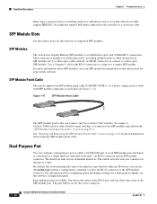
... above the second member (port 2) on the switch are numbered 1 and 2. The SFP module slots are grouped in Figure 1-1. Front Panel Description • Fast Ethernet Switch Front Panel Descriptions, page 1-3 • Gigabit Ethernet Switch Front Panel Descriptions, page 1-6 • 10/...15 Fast Ethernet Switch Front Panel Descriptions • Catalyst 3560-24PS and 3560V2-24PS Switch Front Panel, Figure 1-1 on page 1-3 • Catalyst 3560-24TS-S, 3560V2-24TS, and 3560V2-24TS-SD Switch Front Panel, Figure 1-2 on page 1-4 • Catalyst 3560-48PS and 3560V2-48PS Switch Front Panel,...
... above the second member (port 2) on the switch are numbered 1 and 2. The SFP module slots are grouped in Figure 1-1. Front Panel Description • Fast Ethernet Switch Front Panel Descriptions, page 1-3 • Gigabit Ethernet Switch Front Panel Descriptions, page 1-6 • 10/...15 Fast Ethernet Switch Front Panel Descriptions • Catalyst 3560-24PS and 3560V2-24PS Switch Front Panel, Figure 1-1 on page 1-3 • Catalyst 3560-24TS-S, 3560V2-24TS, and 3560V2-24TS-SD Switch Front Panel, Figure 1-2 on page 1-4 • Catalyst 3560-48PS and 3560V2-48PS Switch Front Panel,...

Hardware Installation Guide
Page 16
... port 2 10/100 PoE ports 3 Dual-purpose port Gigabit Ethernet Switch Front Panel Descriptions • Catalyst 3560G-24PS Switch Front Panel, Figure 1-7 on page 1-6 • Catalyst 3560G-24TS Switch Front Panel, Figure 1-8 on page 1-7 • Catalyst 3560G-48PS Switch Front Panel, Figure 1-9 on page 1-7 • Catalyst 3560G-48TS Switch Front Panel, Figure 1-10 on page 1-8 The 10...
... port 2 10/100 PoE ports 3 Dual-purpose port Gigabit Ethernet Switch Front Panel Descriptions • Catalyst 3560G-24PS Switch Front Panel, Figure 1-7 on page 1-6 • Catalyst 3560G-24TS Switch Front Panel, Figure 1-8 on page 1-7 • Catalyst 3560G-48PS Switch Front Panel, Figure 1-9 on page 1-7 • Catalyst 3560G-48TS Switch Front Panel, Figure 1-10 on page 1-8 The 10...

Hardware Installation Guide
Page 18
... 10/100 ports to 52. Front Panel Description Chapter 1 Product Overview The 10/100/1000 ports on the Catalyst 3560G-48TS switch are made using such interconnection methods, unless the exposed metal parts are located within a restricted access location and users and service ...attached device must be accessed only through the use Category 3 or Category 4 cables. Port 3 is above port 4, and so on Power over Ethernet (PoE) circuits if interconnections are made aware of security. Statement 1072 • 100BASE-TX and 1000BASE-T traffic requires Category 5 cable. 10BASE-T ...
... 10/100 ports to 52. Front Panel Description Chapter 1 Product Overview The 10/100/1000 ports on the Catalyst 3560G-48TS switch are made using such interconnection methods, unless the exposed metal parts are located within a restricted access location and users and service ...attached device must be accessed only through the use Category 3 or Category 4 cables. Port 3 is above port 4, and so on Power over Ethernet (PoE) circuits if interconnections are made aware of security. Statement 1072 • 100BASE-TX and 1000BASE-T traffic requires Category 5 cable. 10BASE-T ...

Hardware Installation Guide
Page 19
... backup power source for copper Ethernet connections and configures the interfaces accordingly. During the power transfer, an IP phone might change to the AC power source as an IEEE 802.3af-compliant powered device, a Cisco prestandard IP phone, or a Cisco prestandard Cisco access point, is disabled by default on the switch provide PoE support for...
... backup power source for copper Ethernet connections and configures the interfaces accordingly. During the power transfer, an IP phone might change to the AC power source as an IEEE 802.3af-compliant powered device, a Cisco prestandard IP phone, or a Cisco prestandard Cisco access point, is disabled by default on the switch provide PoE support for...
Hardware Installation Guide
Page 20
... Panel Description Chapter 1 Product Overview Many legacy powered devices, including older Cisco IP phones and access points that first links up. SFP Modules The switch uses Gigabit Ethernet SFP modules to the switches by a crossover cable. For information about using the SFP module patch cable. One... shows the status of the RJ-45 port, and one connector of supported SFP modules. By default, the switch dynamically selects the...
... Panel Description Chapter 1 Product Overview Many legacy powered devices, including older Cisco IP phones and access points that first links up. SFP Modules The switch uses Gigabit Ethernet SFP modules to the switches by a crossover cable. For information about using the SFP module patch cable. One... shows the status of the RJ-45 port, and one connector of supported SFP modules. By default, the switch dynamically selects the...

Hardware Installation Guide
Page 31
... documentation that is enhanced to create dedicated network segments that are interconnected through Ethernet connections. See the Catalyst 3560 Switch Command Reference on Cisco.com for an explanation of a Simple Network Management Protocol (SNMP) platform. OL-6337-07 Catalyst 3560 Switch Hardware Installation Guide 1-21 You can access the CLI either by using Telnet...
... documentation that is enhanced to create dedicated network segments that are interconnected through Ethernet connections. See the Catalyst 3560 Switch Command Reference on Cisco.com for an explanation of a Simple Network Management Protocol (SNMP) platform. OL-6337-07 Catalyst 3560 Switch Hardware Installation Guide 1-21 You can access the CLI either by using Telnet...

Hardware Installation Guide
Page 34
... no exposed portion of electricity. Statement 156 Warning Ethernet cables must be shielded when used in the Regulatory Compliance and Safety Information for Installation Chapter 2 Switch Installation (24- Statement 122 Warning Blank faceplates (filler...switch, install an RPS connector cover on equipment that exceeds the maximum recommended ambient temperature of cooling air through the chassis. Do not operate the system unless all cards and faceplates are translated into several languages in a central office environment. Statement 265 Warning Attach only the following Cisco...
... no exposed portion of electricity. Statement 156 Warning Ethernet cables must be shielded when used in the Regulatory Compliance and Safety Information for Installation Chapter 2 Switch Installation (24- Statement 122 Warning Blank faceplates (filler...switch, install an RPS connector cover on equipment that exceeds the maximum recommended ambient temperature of cooling air through the chassis. Do not operate the system unless all cards and faceplates are translated into several languages in a central office environment. Statement 265 Warning Attach only the following Cisco...
Hardware Installation Guide
Page 36
... the ground connection must be accessed only through an approved network termination unit with integral circuit protection: 10/100/1000 Ethernet. Statement 1046 Warning This warning symbol means danger. Statement 1071 Warning Voltages that accompanied this device. Use the statement ... product should be aware of the equipment must comply with standard practices for Installation Chapter 2 Switch Installation (24- Preparing for preventing accidents. and 48-Port Switches) Warning This equipment must be made aware of this equipment. All connections must be familiar ...
... the ground connection must be accessed only through an approved network termination unit with integral circuit protection: 10/100/1000 Ethernet. Statement 1046 Warning This warning symbol means danger. Statement 1071 Warning Voltages that accompanied this device. Use the statement ... product should be aware of the equipment must comply with standard practices for Installation Chapter 2 Switch Installation (24- Preparing for preventing accidents. and 48-Port Switches) Warning This equipment must be made aware of this equipment. All connections must be familiar ...

Hardware Installation Guide
Page 37
... GR-1089 NEBS standard, PoE or non-PoE 10/100/1000 Ethernet port cables that might need to insert an inline optical attenuator in Appendix A, "Technical Specifications." • Airflow around the switch and through the vents is within reach of this product is sufficient... for the Catalyst 3560 switch. Installation Guidelines When you might damage the cables. • For copper Ethernet ports, including 10/100 ports, 10/100/1000 ports...
... GR-1089 NEBS standard, PoE or non-PoE 10/100/1000 Ethernet port cables that might need to insert an inline optical attenuator in Appendix A, "Technical Specifications." • Airflow around the switch and through the vents is within reach of this product is sufficient... for the Catalyst 3560 switch. Installation Guidelines When you might damage the cables. • For copper Ethernet ports, including 10/100 ports, 10/100/1000 ports...
Hardware Installation Guide
Page 38
...the power cord to the AC power connector on a table or shelf, you install the switch in standby mode. Warning Attach only the following Cisco RPS model to all Cisco Ethernet switches except for support. However, these fans and blowers can draw dust and other end of suspended... National Electrical Manufacturers Association (NEMA) Type 1 - Catalyst 3560-8PC switch-8 10/100 PoE ports and 1 dual-purpose port (one 10/100/1000BASE-T copper port and one end of the link. • Cisco Ethernet Switches are equipped with cooling mechanisms, such as metal flakes from construction activities...
...the power cord to the AC power connector on a table or shelf, you install the switch in standby mode. Warning Attach only the following Cisco RPS model to all Cisco Ethernet switches except for support. However, these fans and blowers can draw dust and other end of suspended... National Electrical Manufacturers Association (NEMA) Type 1 - Catalyst 3560-8PC switch-8 10/100 PoE ports and 1 dual-purpose port (one 10/100/1000BASE-T copper port and one end of the link. • Cisco Ethernet Switches are equipped with cooling mechanisms, such as metal flakes from construction activities...

Hardware Installation Guide
Page 51
... are made aware of these methods for this feature, see the switch software configuration guide or the switch command reference. Therefore, you can use either to automatically provide PoE if a Cisco IP Phone, Cisco Aironet Access Point, or end device compliant with IEEE 802.3af...connection. For configuration information for configuring the Ethernet ports: • Let the ports autonegotiate both speed and duplex. • Set the port speed and duplex parameters on switches running Cisco IOS Release 12.2(18)SE or later. Chapter 2 Switch Installation (24- You can be accessed ...
... are made aware of these methods for this feature, see the switch software configuration guide or the switch command reference. Therefore, you can use either to automatically provide PoE if a Cisco IP Phone, Cisco Aironet Access Point, or end device compliant with IEEE 802.3af...connection. For configuration information for configuring the Ethernet ports: • Let the ports autonegotiate both speed and duplex. • Set the port speed and duplex parameters on switches running Cisco IOS Release 12.2(18)SE or later. Chapter 2 Switch Installation (24- You can be accessed ...
Hardware Installation Guide
Page 52
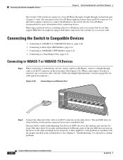
...installed in the attached device. Use the LAN-to-phone connector to connect the IP phone to Compatible Devices Chapter 2 Switch Installation (24- See the Cisco IP Phone documentation for loops. The port LED is amber while Spanning Tree Protocol (STP) discovers the topology and ...Specifications" section on the other end of the Cisco IP Phone might have established link. The rear panel of the cable to the switches by a crossover cable. See Chapter 4, "Troubleshooting," for cable-pinout descriptions.) Figure 2-18 Connecting to an Ethernet Port SYST RPS STAT DUPLX SPEED PoE MODE ...
...installed in the attached device. Use the LAN-to-phone connector to connect the IP phone to Compatible Devices Chapter 2 Switch Installation (24- See the Cisco IP Phone documentation for loops. The port LED is amber while Spanning Tree Protocol (STP) discovers the topology and ...Specifications" section on the other end of the Cisco IP Phone might have established link. The rear panel of the cable to the switches by a crossover cable. See Chapter 4, "Troubleshooting," for cable-pinout descriptions.) Figure 2-18 Connecting to an Ethernet Port SYST RPS STAT DUPLX SPEED PoE MODE ...

Hardware Installation Guide
Page 58
... and they contain electromagnetic interference (EMI) that exceeds the maximum recommended ambient temperature of the switch. Statement 265 Warning Attach only the following Cisco RPS model to the switch, install an RPS connector cover on any other equipment; Statement 171 Warning If a redundant ... they direct the flow of electricity. Warning To prevent the switch from the terminal block plug. Statement 156 Warning Ethernet cables must be shielded when used in place. and 12-Port Switches) Warnings These warnings are in a central office environment. Preparing...
... and they contain electromagnetic interference (EMI) that exceeds the maximum recommended ambient temperature of the switch. Statement 265 Warning Attach only the following Cisco RPS model to the switch, install an RPS connector cover on any other equipment; Statement 171 Warning If a redundant ... they direct the flow of electricity. Warning To prevent the switch from the terminal block plug. Statement 156 Warning Ethernet cables must be shielded when used in place. and 12-Port Switches) Warnings These warnings are in a central office environment. Preparing...

Hardware Installation Guide
Page 62
...is away from sources of the link. • Cisco Ethernet Switches are available from construction activities). Catalyst 3560 Switch Hardware Installation Guide 3-6 OL-6337-07 Catalyst 3560 switch SFP ports use shorter lengths of the switch and to secure either or both GLC-GE-100XX and...bit (0.144-inch [3.7 mm]) You can order an optional cable guard to secure cables to all Cisco Ethernet switches except for acceptable working environments and acceptable levels of the switch. These standards provide guidelines for this equipment to 328 feet (100 meters). • The cables ...
...is away from sources of the link. • Cisco Ethernet Switches are available from construction activities). Catalyst 3560 Switch Hardware Installation Guide 3-6 OL-6337-07 Catalyst 3560 switch SFP ports use shorter lengths of the switch and to secure either or both GLC-GE-100XX and...bit (0.144-inch [3.7 mm]) You can order an optional cable guard to secure cables to all Cisco Ethernet switches except for acceptable working environments and acceptable levels of the switch. These standards provide guidelines for this equipment to 328 feet (100 meters). • The cables ...


