Installation Guide
Page 6
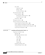
... Up the Switch 2-1 Preparing for Using the Switch 1-25 Small- Contents 2 C H A P T E R LEDs 1-11 System LED 1-14 RPS LED 1-15 Port LEDs and Modes 1-16 Rear-Panel Description 1-21 Power Connectors 1-22 Internal Power Supply Connector 1-23 Cisco RPS Connector 1-23 Console Port 1-24 Management Options 1-24 Network Configuration Examples 1-25 Design Concepts for Installation 2-2 Warnings 2-2 EMC Regulatory Statements 2-5 U.S.A. 2-5 Taiwan 2-5 Japan 2-6 Korea 2-6 Hungary 2-7 Installation Guidelines 2-7 Verifying Package Contents 2-8 Catalyst 3500 Series XL Hardware Installation Guide vi 78...
... Up the Switch 2-1 Preparing for Using the Switch 1-25 Small- Contents 2 C H A P T E R LEDs 1-11 System LED 1-14 RPS LED 1-15 Port LEDs and Modes 1-16 Rear-Panel Description 1-21 Power Connectors 1-22 Internal Power Supply Connector 1-23 Cisco RPS Connector 1-23 Console Port 1-24 Management Options 1-24 Network Configuration Examples 1-25 Design Concepts for Installation 2-2 Warnings 2-2 EMC Regulatory Statements 2-5 U.S.A. 2-5 Taiwan 2-5 Japan 2-6 Korea 2-6 Hungary 2-7 Installation Guidelines 2-7 Verifying Package Contents 2-8 Catalyst 3500 Series XL Hardware Installation Guide vi 78...

Installation Guide
Page 12
... describes the switch ports, the standards they support, and the switch LEDs. Examples of how the switch could be used to connect to identify and resolve some of the switch. Appendix A, "Technical Specifications," lists the physical and environmental specifications for installing a switch on a rack, wall, table, or shelf. Catalyst 3500 Series XL Hardware Installation Guide xii 78-6456-04 Appendix B, "Connector and Cable Specifications," describes the connectors, cables, and adapters that can be installed suggest possible deployment...
... describes the switch ports, the standards they support, and the switch LEDs. Examples of how the switch could be used to connect to identify and resolve some of the switch. Appendix A, "Technical Specifications," lists the physical and environmental specifications for installing a switch on a rack, wall, table, or shelf. Catalyst 3500 Series XL Hardware Installation Guide xii 78-6456-04 Appendix B, "Connector and Cable Specifications," describes the connectors, cables, and adapters that can be installed suggest possible deployment...
Installation Guide
Page 25
... as backbone switches, aggregating 10/100 and Gigabit Ethernet traffic from other switches. A feature specific to the Catalyst 3524-PWR XL switch is its ability to provide inline power to Cisco IP Phones. (Phone adapters are stackable 10/100 Ethernet switches to the Catalyst 3524-PWR XL 10/100 switch ports.) Figure 1-1 shows the switch models in different network topologies Features The Catalyst 3500 series XL switches-also referred to as Catalyst 3500 XL switches-are...
... as backbone switches, aggregating 10/100 and Gigabit Ethernet traffic from other switches. A feature specific to the Catalyst 3524-PWR XL switch is its ability to provide inline power to Cisco IP Phones. (Phone adapters are stackable 10/100 Ethernet switches to the Catalyst 3524-PWR XL 10/100 switch ports.) Figure 1-1 shows the switch models in different network topologies Features The Catalyst 3500 series XL switches-also referred to as Catalyst 3500 XL switches-are...
Installation Guide
Page 27
... XL switch) Management • Cisco IOS command-line interface (CLI) through the console port or Telnet • CiscoView device-management application • Cluster Management Suite, a web-based tool for managing switch clusters or an individual switch through a single IP address • Simple Network Management Protocol (SNMP) Power Redundancy • Connection for optional Cisco 600W Redundant Power System (RPS) that operates on AC input and supplies DC output to prevent performance degradation from broadcast storms • Switch Port Analyzer (SPAN) port monitoring...
... XL switch) Management • Cisco IOS command-line interface (CLI) through the console port or Telnet • CiscoView device-management application • Cluster Management Suite, a web-based tool for managing switch clusters or an individual switch through a single IP address • Simple Network Management Protocol (SNMP) Power Redundancy • Connection for optional Cisco 600W Redundant Power System (RPS) that operates on AC input and supplies DC output to prevent performance degradation from broadcast storms • Switch Port Analyzer (SPAN) port monitoring...

Installation Guide
Page 29
... Figure 1-6) have a set of LEDs and a Mode button. (The Catalyst 3548 XL switch has a Mode label that operates on AC input and supplies DC output to the Catalyst 3524-PWR XL switch Inline Power (Catalyst 3524-PWR XL switch only) • Ability to provide inline power for Cisco IP Phones from all 24 10/100 Ethernet ports • Auto-detection and control of the Catalyst 3508G XL switch (Figure 1-2) has eight...
... Figure 1-6) have a set of LEDs and a Mode button. (The Catalyst 3548 XL switch has a Mode label that operates on AC input and supplies DC output to the Catalyst 3524-PWR XL switch Inline Power (Catalyst 3524-PWR XL switch only) • Ability to provide inline power for Cisco IP Phones from all 24 10/100 Ethernet ports • Auto-detection and control of the Catalyst 3508G XL switch (Figure 1-2) has eight...
Installation Guide
Page 32
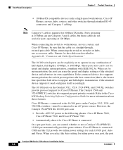
... DC power to the Cisco IOS Desktop Switching Software Configuration Guide for inline power on a port, the port Catalyst 3500 Series XL Hardware Installation Guide 1-8 78-6456-04 If the connected device also supports autonegotiation, the switch port negotiates the best connection (that is, the fastest line speed that the cable is a straight-through standard RJ-45 connectors and Category 5 cabling Note Category 5 cable is connected On a per -port priority override. When you can use a crossover cable. The...
... DC power to the Cisco IOS Desktop Switching Software Configuration Guide for inline power on a port, the port Catalyst 3500 Series XL Hardware Installation Guide 1-8 78-6456-04 If the connected device also supports autonegotiation, the switch port negotiates the best connection (that is, the fastest line speed that the cable is a straight-through standard RJ-45 connectors and Category 5 cabling Note Category 5 cable is connected On a per -port priority override. When you can use a crossover cable. The...
Installation Guide
Page 33
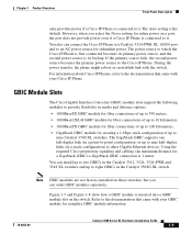
... Series XL Hardware Installation Guide 1-9 Using the required Cisco proprietary signaling and cabling, the maximum distance for a GigaStack GBIC-to-GigaStack GBIC connection is the default. You can install up to two GBICs in the Catalyst 3512, 3524, 3524-PWR and 3548 XL switches and up to nine half-duplex links (in the Catalyst 3508G XL switch. The Auto setting is 1 meter. If the primary source fails, the second power...
... Series XL Hardware Installation Guide 1-9 Using the required Cisco proprietary signaling and cabling, the maximum distance for a GigaStack GBIC-to-GigaStack GBIC connection is the default. You can install up to two GBICs in the Catalyst 3512, 3524, 3524-PWR and 3548 XL switches and up to nine half-duplex links (in the Catalyst 3508G XL switch. The Auto setting is 1 meter. If the primary source fails, the second power...
Installation Guide
Page 39
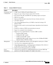
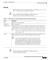
Table 1-4 RPS LED for RPS revision level Z3 or later. If the switch power supply fails, the switch powers down , or a fan on the bottom of the power supplies in the RPS could have failed. Note The Cisco RPS 300 (model PWR300-AC-RPS) supports the Catalyst 3524-PWR XL switch. 78-6456-04 Catalyst 3500 Series XL Hardware Installation Guide 1-15 RPS is not a recommended configuration. RPS and the switch AC power supply are using power from the...
Table 1-4 RPS LED for RPS revision level Z3 or later. If the switch power supply fails, the switch powers down , or a fan on the bottom of the power supplies in the RPS could have failed. Note The Cisco RPS 300 (model PWR300-AC-RPS) supports the Catalyst 3524-PWR XL switch. 78-6456-04 Catalyst 3500 Series XL Hardware Installation Guide 1-15 RPS is not a recommended configuration. RPS and the switch AC power supply are using power from the...
Installation Guide
Page 40
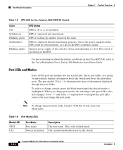
... on the RPS. One of the switch is down , or a fan on the RPS could have failed. The switch is not installed. Table 1-7 and Table 1-8 explain how to the Cisco Redundant Power System 300 Hardware Installation Guide. RPS is connected but not functioning properly. RPS is backing up another switch in use by the switch. 1-16 Catalyst 3500 Series XL Hardware Installation Guide 78-6456-04 Table 1-6 Port Mode LEDs Mode LED STAT UTL Port Mode Port status Switch utilization Description The port status.
... on the RPS. One of the switch is down , or a fan on the RPS could have failed. The switch is not installed. Table 1-7 and Table 1-8 explain how to the Cisco Redundant Power System 300 Hardware Installation Guide. RPS is connected but not functioning properly. RPS is backing up another switch in use by the switch. 1-16 Catalyst 3500 Series XL Hardware Installation Guide 78-6456-04 Table 1-6 Port Mode LEDs Mode LED STAT UTL Port Mode Port status Switch utilization Description The port status.

Installation Guide
Page 41
... Catalyst 3500 Series XL Hardware Installation Guide 1-17 Table 1-7 Meaning of its total capacity, and so on a logarithmic scale. Link present. Activity. Port is transmitting or receiving data. The inline power status: on the Catalyst 3508, 3512, 3524, and 3548 XL Switches Port Mode STATUS (port status) UTL (utilization) DUPLEX LED Color Off Solid green Flashing green Alternating green-amber Solid amber Green Off Green Meaning No link. Note After a port is reconfigured, the port LED can affect connectivity, and errors such as STP checks the switch...
... Catalyst 3500 Series XL Hardware Installation Guide 1-17 Table 1-7 Meaning of its total capacity, and so on a logarithmic scale. Link present. Activity. Port is transmitting or receiving data. The inline power status: on the Catalyst 3508, 3512, 3524, and 3548 XL Switches Port Mode STATUS (port status) UTL (utilization) DUPLEX LED Color Off Solid green Flashing green Alternating green-amber Solid amber Green Off Green Meaning No link. Note After a port is reconfigured, the port LED can affect connectivity, and errors such as STP checks the switch...
Installation Guide
Page 49
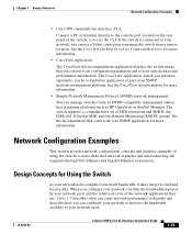
... they use a Telnet connection to manage the switch from an SNMP-compatible management station that came with your network users. 78-6456-04 Catalyst 3500 Series XL Hardware Installation Guide 1-25 Chapter 1 Product Overview Network Configuration Examples • Cisco IOS command-line interface (CLI) Connect a PC or terminal directly to the console port, located on the rear panel of using the switch to create dedicated network segments and interconnecting the segments through Fast Ethernet and Gigabit Ethernet connections. See the Cisco IOS Desktop Switching Command Reference for...
... they use a Telnet connection to manage the switch from an SNMP-compatible management station that came with your network users. 78-6456-04 Catalyst 3500 Series XL Hardware Installation Guide 1-25 Chapter 1 Product Overview Network Configuration Examples • Cisco IOS command-line interface (CLI) Connect a PC or terminal directly to the console port, located on the rear panel of using the switch to create dedicated network segments and interconnecting the segments through Fast Ethernet and Gigabit Ethernet connections. See the Cisco IOS Desktop Switching Command Reference for...
Installation Guide
Page 50
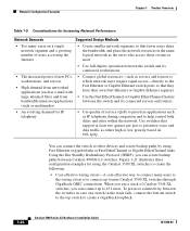
... a growing number of users accessing the Internet • Create smaller network segments so that they have their own Fast Ethernet or Gigabit Ethernet segment. • Use the Fast EtherChannel or Gigabit EtherChannel feature between the switch and its connected workstations. • The increased power of Catalyst 3548 XL switches, you can connect the switch to nine Catalyst 3500 XL switches through GigaStack GBIC connections. Network Configuration Examples Chapter 1 Product Overview Table 1-9 Considerations for Increasing Network Performance Network Demands...
... a growing number of users accessing the Internet • Create smaller network segments so that they have their own Fast Ethernet or Gigabit Ethernet segment. • Use the Fast EtherChannel or Gigabit EtherChannel feature between the switch and its connected workstations. • The increased power of Catalyst 3548 XL switches, you can connect the switch to nine Catalyst 3500 XL switches through GigaStack GBIC connections. Network Configuration Examples Chapter 1 Product Overview Table 1-9 Considerations for Increasing Network Performance Network Demands...

Installation Guide
Page 51
...-6456-04 Catalyst 3500 Series XL Hardware Installation Guide 1-27 Compare this configuration provides users a dedicated 1-Gbps connection to a backbone switch in a star configuration, to a gigabit backbone switch such as the Catalyst 3508G XL switch. Chapter 1 Product Overview Network Configuration Examples Using gigabit GBIC modules on two of the switches, you can connect the Catalyst 3500 XL switches, again in a star configuration. Using gigabit GBIC modules also provides flexibility in media and distance options: - 1000BaseSX GBIC module: Fiber connections of up...
...-6456-04 Catalyst 3500 Series XL Hardware Installation Guide 1-27 Compare this configuration provides users a dedicated 1-Gbps connection to a backbone switch in a star configuration, to a gigabit backbone switch such as the Catalyst 3508G XL switch. Chapter 1 Product Overview Network Configuration Examples Using gigabit GBIC modules on two of the switches, you can connect the Catalyst 3500 XL switches, again in a star configuration. Using gigabit GBIC modules also provides flexibility in media and distance options: - 1000BaseSX GBIC module: Fiber connections of up...
Installation Guide
Page 55
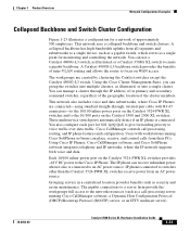
... create a gigabit backbone. The workgroups are connected-using standard straight-through the IP address of its primary and secondary command switches, regardless of the geographic location of approximately 500 employees. Each 10/100 inline-power port on WAN access. Using Cisco IP Phones, Cisco CallManager software, and Cisco SoftPhone software integrates telephony and IP networks, where the IP network supports both voice and data. Cisco CallManager controls call -processing server running Cisco SoftPhone software can use a Catalyst...
... create a gigabit backbone. The workgroups are connected-using standard straight-through the IP address of its primary and secondary command switches, regardless of the geographic location of approximately 500 employees. Each 10/100 inline-power port on WAN access. Using Cisco IP Phones, Cisco CallManager software, and Cisco SoftPhone software integrates telephony and IP networks, where the IP network supports both voice and data. Cisco CallManager controls call -processing server running Cisco SoftPhone software can use a Catalyst...

Installation Guide
Page 59
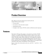
... how to install and start up your Catalyst 3500 XL switches and to interpret the power-on self-test (POST) that they are presented: • Pre-installation information and guidelines • Installation procedures • Power-on procedures • Connection procedures • Set up procedures for initial configuration • Default configuration settings • Where to go next 78-6456-04 Catalyst 3500 Series XL Hardware Installation Guide 2-1 Read the...
... how to install and start up your Catalyst 3500 XL switches and to interpret the power-on self-test (POST) that they are presented: • Pre-installation information and guidelines • Installation procedures • Power-on procedures • Connection procedures • Set up procedures for initial configuration • Default configuration settings • Where to go next 78-6456-04 Catalyst 3500 Series XL Hardware Installation Guide 2-1 Read the...

Installation Guide
Page 83
... Management Suite or the command-line interface (CLI) to customize your system administrator: Switch IP address Subnet mask (netmask 78-6456-04 Catalyst 3500 Series XL Hardware Installation Guide 2-25 To run the setup program, access the switch from your configuration. Later, you can use the Cluster Management Suite to configure and manage the switch. Refer to the Cisco IOS Desktop Switching Software Configuration Guide for the switch to assign IP information or a password. The first time that you access the switch...
... Management Suite or the command-line interface (CLI) to customize your system administrator: Switch IP address Subnet mask (netmask 78-6456-04 Catalyst 3500 Series XL Hardware Installation Guide 2-25 To run the setup program, access the switch from your configuration. Later, you can use the Cluster Management Suite to configure and manage the switch. Refer to the Cisco IOS Desktop Switching Software Configuration Guide for the switch to assign IP information or a password. The first time that you access the switch...

Installation Guide
Page 87
... information, such as the corresponding subnet masks and default gateway addresses, can also be able to all of its physical MAC address. The switch must be set , but the saved configuration in Table 2-1. 78-6456-04 Catalyst 3500 Series XL Hardware Installation Guide 2-29 If the switch starts and no IP address has been assigned, it resets. To save the IP information, log in the database. A valid response includes the...
... information, such as the corresponding subnet masks and default gateway addresses, can also be able to all of its physical MAC address. The switch must be set , but the saved configuration in Table 2-1. 78-6456-04 Catalyst 3500 Series XL Hardware Installation Guide 2-29 If the switch starts and no IP address has been assigned, it resets. To save the IP information, log in the database. A valid response includes the...

Installation Guide
Page 89
... release notes on using the CLI with Catalyst 3500 XL switches. • Start an SNMP application such as the CiscoView application. 78-6456-04 Catalyst 3500 Series XL Hardware Installation Guide 2-31 CDP = Cisco Discovery Protocol 2. Where to Go Next Table 2-1 Default Configuration Settings (continued) Feature Diagnostics SPAN5 port monitoring Console, buffer, and file logging Security Password Addressing security Trap manager Community strings Port security Inline Power Inline power mode 1. SPAN = Switched Port Analyzer Default Setting Disabled. Chapter 2 Installing and Starting...
... release notes on using the CLI with Catalyst 3500 XL switches. • Start an SNMP application such as the CiscoView application. 78-6456-04 Catalyst 3500 Series XL Hardware Installation Guide 2-31 CDP = Cisco Discovery Protocol 2. Where to Go Next Table 2-1 Default Configuration Settings (continued) Feature Diagnostics SPAN5 port monitoring Console, buffer, and file logging Security Password Addressing security Trap manager Community strings Port security Inline Power Inline power mode 1. SPAN = Switched Port Analyzer Default Setting Disabled. Chapter 2 Installing and Starting...

Installation Guide
Page 91
...-test (POST), port-connectivity problems, and overall switch performance. You can also get statistics from the browser interface, from the command-line interface (CLI), or from an Simple Network Management Protocol (SNMP) workstation. See the Cisco IOS Desktop Switching Software Configuration Guide, the Cisco IOS Desktop Switching Command Reference (online only), or the documentation that came with your SNMP application for troubleshooting problems: • Understanding POST results • Diagnosing problems 78-6456-04 Catalyst 3500 Series XL Hardware Installation Guide 3-1 This...
...-test (POST), port-connectivity problems, and overall switch performance. You can also get statistics from the browser interface, from the command-line interface (CLI), or from an Simple Network Management Protocol (SNMP) workstation. See the Cisco IOS Desktop Switching Software Configuration Guide, the Cisco IOS Desktop Switching Command Reference (online only), or the documentation that came with your SNMP application for troubleshooting problems: • Understanding POST results • Diagnosing problems 78-6456-04 Catalyst 3500 Series XL Hardware Installation Guide 3-1 This...

Installation Guide
Page 96
Cisco IP Phone fails to check if an overtemperature condition exists. Replace the switch at your convenience. • Use the show env command to power on the Cisco IP Phone. Place the switch in an environment that is within 32 to 113°F (0 to a Catalyst 3524-PWR XL switch. Make sure fan intake and exhaust areas are clear. Catalyst 3500 Series XL Hardware Installation Guide 3-6 78-6456-04 Possible Cause...
Cisco IP Phone fails to check if an overtemperature condition exists. Replace the switch at your convenience. • Use the show env command to power on the Cisco IP Phone. Place the switch in an environment that is within 32 to 113°F (0 to a Catalyst 3524-PWR XL switch. Make sure fan intake and exhaust areas are clear. Catalyst 3500 Series XL Hardware Installation Guide 3-6 78-6456-04 Possible Cause...

