Installation Guide
Page 6
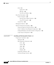
... and Modes 1-16 Rear-Panel Description 1-21 Power Connectors 1-22 Internal Power Supply Connector 1-23 Cisco RPS Connector 1-23 Console Port 1-24 Management Options 1-24 Network Configuration Examples 1-25 Design Concepts for Installation 2-2 Warnings 2-2 EMC Regulatory Statements 2-5 U.S.A. 2-5 Taiwan 2-5 Japan 2-6 Korea 2-6 Hungary 2-7 Installation Guidelines 2-7 Verifying Package Contents 2-8 Catalyst 3500 Series XL Hardware Installation Guide vi 78...
... and Modes 1-16 Rear-Panel Description 1-21 Power Connectors 1-22 Internal Power Supply Connector 1-23 Cisco RPS Connector 1-23 Console Port 1-24 Management Options 1-24 Network Configuration Examples 1-25 Design Concepts for Installation 2-2 Warnings 2-2 EMC Regulatory Statements 2-5 U.S.A. 2-5 Taiwan 2-5 Japan 2-6 Korea 2-6 Hungary 2-7 Installation Guidelines 2-7 Verifying Package Contents 2-8 Catalyst 3500 Series XL Hardware Installation Guide vi 78...

Installation Guide
Page 9
INDEX Grounded Equipment Warning C-23 Supply Circuit Warning C-24 No On/Off Switch Warning C-25 Power Supply Warning C-27 Work During Lightning Activity Warning C-30 Product Disposal Warning C-31 Chassis Warning-Rack-Mounting and Servicing C-33 Chassis Power Connection Warning C-38 Shock Hazard from Interconnections Warning C-41 Contents 78-6456-03 Catalyst 3500 Series XL Hardware Installation Guide ix
INDEX Grounded Equipment Warning C-23 Supply Circuit Warning C-24 No On/Off Switch Warning C-25 Power Supply Warning C-27 Work During Lightning Activity Warning C-30 Product Disposal Warning C-31 Chassis Warning-Rack-Mounting and Servicing C-33 Chassis Power Connection Warning C-38 Shock Hazard from Interconnections Warning C-41 Contents 78-6456-03 Catalyst 3500 Series XL Hardware Installation Guide ix
Installation Guide
Page 27
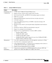
... 8 GBIC-based 1000BaseX Gigabit Ethernet slots Configuration • Support for up to four 1000BaseZX GBICs with the Catalyst 3508G XL switch) Management • Cisco IOS command-line interface (CLI) through the console port or Telnet • CiscoView device-management application •...web-based tool for managing switch clusters or an individual switch through a single IP address • Simple Network Management Protocol (SNMP) Power Redundancy • Connection for optional Cisco 600W Redundant Power System (RPS) that operates on AC input and supplies DC output to prevent ...
... 8 GBIC-based 1000BaseX Gigabit Ethernet slots Configuration • Support for up to four 1000BaseZX GBICs with the Catalyst 3508G XL switch) Management • Cisco IOS command-line interface (CLI) through the console port or Telnet • CiscoView device-management application •...web-based tool for managing switch clusters or an individual switch through a single IP address • Simple Network Management Protocol (SNMP) Power Redundancy • Connection for optional Cisco 600W Redundant Power System (RPS) that operates on AC input and supplies DC output to prevent ...

Installation Guide
Page 29
...set of LEDs and a Mode button. (The Catalyst 3548 XL switch has a Mode label that operates on AC input and supplies DC output to the Catalyst 3524-PWR XL switch Inline Power (Catalyst 3524-PWR XL switch only) • Ability to provide inline power for Cisco IP Phones from all 24 10/100 Ethernet ports... • Auto-detection and control of inline phone power on a per-port ...
...set of LEDs and a Mode button. (The Catalyst 3548 XL switch has a Mode label that operates on AC input and supplies DC output to the Catalyst 3524-PWR XL switch Inline Power (Catalyst 3524-PWR XL switch only) • Ability to provide inline power for Cisco IP Phones from all 24 10/100 Ethernet ports... • Auto-detection and control of inline phone power on a per-port ...
Installation Guide
Page 39
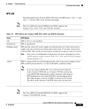
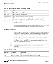
...or later. If the switch power supply fails, the switch powers down , or a fan on . The LEDs display correctly for the Catalyst 3508, 3512, 3524, and 3548 XL Switches Color Off Solid green Blinking green Amber RPS Status RPS is off or is operational. Note The Cisco RPS 300 (model PWR300... properly. The label on page 1-23. For more information see the "RPS Connector on the Catalyst 3508, 3512, 3524, and 3548 XL Switches" section on the bottom of the power supplies in the RPS could have failed. Note This is not a recommended configuration. Chapter 1 Product Overview...
...or later. If the switch power supply fails, the switch powers down , or a fan on . The LEDs display correctly for the Catalyst 3508, 3512, 3524, and 3548 XL Switches Color Off Solid green Blinking green Amber RPS Status RPS is off or is operational. Note The Cisco RPS 300 (model PWR300... properly. The label on page 1-23. For more information see the "RPS Connector on the Catalyst 3508, 3512, 3524, and 3548 XL Switches" section on the bottom of the power supplies in the RPS could have failed. Note This is not a recommended configuration. Chapter 1 Product Overview...
Installation Guide
Page 40
... type of the switch is down , or a fan on the Cisco RPS 300, refer to interpret the port LED colors after you change the port mode in use by the switch. 1-16 Catalyst 3500 Series XL Hardware Installation Guide 78-6456-04 Note To change port modes, the meaning of the power supplies in the stack...
... type of the switch is down , or a fan on the Cisco RPS 300, refer to interpret the port LED colors after you change the port mode in use by the switch. 1-16 Catalyst 3500 Series XL Hardware Installation Guide 78-6456-04 Note To change port modes, the meaning of the power supplies in the stack...

Installation Guide
Page 45
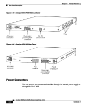
... Rear-Panel Description Rear-Panel Description Switch rear panels have an AC power connector, an RPS connector, and an RJ-45 console port (see Figure 1-17, Figure 1-19, Figure 1-18, and Figure 1-20), which are described in this section. Figure 1-17 Catalyst 3508G XL Rear Panel 18963 RATING ...DC INPUT +12V***@3A AC power connector RJ-45 console port Redundant power system connector Figure 1-18 Catalyst 3512 and 3524 XL Rear Panel Fans 18964 RATING 100-127/200-240V~ 1.0A/0.5A 50-60HZ AC power connector 78-6456-04 CONSOLE DC INPUTS FOR REMOTE POWER SUPPLY SPECIFIED IN MANUAL. +5V ...
... Rear-Panel Description Rear-Panel Description Switch rear panels have an AC power connector, an RPS connector, and an RJ-45 console port (see Figure 1-17, Figure 1-19, Figure 1-18, and Figure 1-20), which are described in this section. Figure 1-17 Catalyst 3508G XL Rear Panel 18963 RATING ...DC INPUT +12V***@3A AC power connector RJ-45 console port Redundant power system connector Figure 1-18 Catalyst 3512 and 3524 XL Rear Panel Fans 18964 RATING 100-127/200-240V~ 1.0A/0.5A 50-60HZ AC power connector 78-6456-04 CONSOLE DC INPUTS FOR REMOTE POWER SUPPLY SPECIFIED IN MANUAL. +5V ...
Installation Guide
Page 46
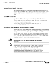
...~ 1.6A/0.9A 50-60HZ DC INPUTS FOR REMOTE POWER SUPPLY SPECIFIED IN MANUAL +3.3V @17A, +12 @1.1A CONSOLE AC power connector Fan exhaust RJ-45 console port Redundant power system connector Power Connectors You can provide power to the switch either through the internal power supply or through the Cisco RPS. 1-22 Catalyst 3500 Series XL Hardware Installation Guide 78-6456...
...~ 1.6A/0.9A 50-60HZ DC INPUTS FOR REMOTE POWER SUPPLY SPECIFIED IN MANUAL +3.3V @17A, +12 @1.1A CONSOLE AC power connector Fan exhaust RJ-45 console port Redundant power system connector Power Connectors You can provide power to the switch either through the internal power supply or through the Cisco RPS. 1-22 Catalyst 3500 Series XL Hardware Installation Guide 78-6456...
Installation Guide
Page 47
... switch power cord to an AC outlet if the switch is also connected to a powered-on the Catalyst 3508, 3512, 3524, and 3548 XL Switches The Cisco RPS 600 (model PWR600-AC-RPS) provides a quasi-redundant power source for the Cisco RPS and one connector at each external device. Chapter 1 Product Overview Rear-Panel Description Internal Power Supply Connector The internal power supply...
... switch power cord to an AC outlet if the switch is also connected to a powered-on the Catalyst 3508, 3512, 3524, and 3548 XL Switches The Cisco RPS 600 (model PWR600-AC-RPS) provides a quasi-redundant power source for the Cisco RPS and one connector at each external device. Chapter 1 Product Overview Rear-Panel Description Internal Power Supply Connector The internal power supply...
Installation Guide
Page 48
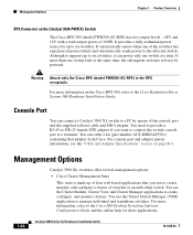
... adapter pinout information, see the "Cable and Adapter Specifications" section on the Catalyst 3524-PWR XL Switch The Cisco RPS 300 (model PWR300-AC-RPS) has two output levels: -48V and 12V with a total output power of the console port and the supplied rollover cable and DB-9 adapter. You need to provide a RJ-45-to...
... adapter pinout information, see the "Cable and Adapter Specifications" section on the Catalyst 3524-PWR XL Switch The Cisco RPS 300 (model PWR300-AC-RPS) has two output levels: -48V and 12V with a total output power of the console port and the supplied rollover cable and DB-9 adapter. You need to provide a RJ-45-to...

Installation Guide
Page 61
...equipment is not overloaded. Statement 20 78-6456-04 Catalyst 3500 Series XL Hardware Installation Guide 2-3 Statement 42 Warning This product relies on /off switch. Statement 51 Warning Unplug the power cord before you work with TN power systems. Statement 19 Warning When installing the unit, ... 120 VAC, 15A U.S. (240 VAC, 10A international) is designed to the supply circuit so that does not have an on the building's installation for Installation Warning To prevent the switch from overheating, do not operate it last. Ensure that exceeds the maximum recommended ...
...equipment is not overloaded. Statement 20 78-6456-04 Catalyst 3500 Series XL Hardware Installation Guide 2-3 Statement 42 Warning This product relies on /off switch. Statement 51 Warning Unplug the power cord before you work with TN power systems. Statement 19 Warning When installing the unit, ... 120 VAC, 15A U.S. (240 VAC, 10A international) is designed to the supply circuit so that does not have an on the building's installation for Installation Warning To prevent the switch from overheating, do not operate it last. Ensure that exceeds the maximum recommended ...
Installation Guide
Page 62
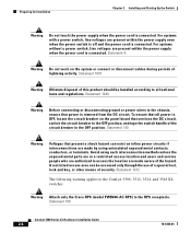
... 1072 The following warning applies to the Catalyst 3508, 3512, 3524, and 3548 XL switches: Warning Attach only the Cisco RPS (model PWR600-AC-RPS) to all power is connected. Statement 4. Preparing for Installation Chapter 2 Installing and Starting Up the Switch Warning Do not touch the power supply when the power cord is removed from the DC circuit...
... 1072 The following warning applies to the Catalyst 3508, 3512, 3524, and 3548 XL switches: Warning Attach only the Cisco RPS (model PWR600-AC-RPS) to all power is connected. Statement 4. Preparing for Installation Chapter 2 Installing and Starting Up the Switch Warning Do not touch the power supply when the power cord is removed from the DC circuit...

Installation Guide
Page 71
... to the switch. After the power is in a 19-inch or 24-inch rack, use the four supplied number-12 ...Catalyst 3500 Series XL Hardware Installation Guide 2-13 Figure 2-5 Mounting the Switch in a Rack 26233 1 SYSTEM 2 3 RPS 4 5 MODE STATUS 6 7 UTIL 8 DUPLX SPEED Phillips machine screws After the switch is mounted in the rack, attach the power...Switch Installing the Switch in a Rack Mounting the Switch in a Rack After the brackets are using the Cisco RPS, see the Cisco RPS documentation for 2 seconds, and then it flashes green while the switch completes the series of the switch...
... to the switch. After the power is in a 19-inch or 24-inch rack, use the four supplied number-12 ...Catalyst 3500 Series XL Hardware Installation Guide 2-13 Figure 2-5 Mounting the Switch in a Rack 26233 1 SYSTEM 2 3 RPS 4 5 MODE STATUS 6 7 UTIL 8 DUPLX SPEED Phillips machine screws After the switch is mounted in the rack, attach the power...Switch Installing the Switch in a Rack Mounting the Switch in a Rack After the brackets are using the Cisco RPS, see the Cisco RPS documentation for 2 seconds, and then it flashes green while the switch completes the series of the switch...
Installation Guide
Page 74
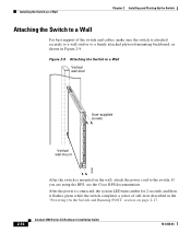
... cables, make sure the switch is mounted on the wall, attach the power cord to a firmly attached plywood mounting backboard, as shown in Figure 2-9. Installing the Switch on page 2-17. 2-16 Catalyst 3500 Series XL Hardware Installation Guide 78-6456-04 Figure 2-9 Attaching the Switch to a Wall Vertical wall stud 8 User-supplied screws 7 6 5 4 3 2 Vertical wall-mount...
... cables, make sure the switch is mounted on the wall, attach the power cord to a firmly attached plywood mounting backboard, as shown in Figure 2-9. Installing the Switch on page 2-17. 2-16 Catalyst 3500 Series XL Hardware Installation Guide 78-6456-04 Figure 2-9 Attaching the Switch to a Wall Vertical wall stud 8 User-supplied screws 7 6 5 4 3 2 Vertical wall-mount...

Installation Guide
Page 82
.... Assigning Switch Information You can assign the switch IP address information, host and cluster names, and passwords by two methods: • Using the setup program in Figure 2-13. Figure 2-13 Connecting to the Console Port 32709 CONSOLE DC INPUTS FOR REMOTE POWER SUPPLY SPECIFIED IN...adapter. Assigning Switch Information Chapter 2 Installing and Starting Up the Switch Step 3 Using the supplied rollover cable, insert the RJ-45 connector into the console port, as shown in the switch • Using a BOOTP server This section describes each method. 2-24 Catalyst 3500 Series...
.... Assigning Switch Information You can assign the switch IP address information, host and cluster names, and passwords by two methods: • Using the setup program in Figure 2-13. Figure 2-13 Connecting to the Console Port 32709 CONSOLE DC INPUTS FOR REMOTE POWER SUPPLY SPECIFIED IN...adapter. Assigning Switch Information Chapter 2 Installing and Starting Up the Switch Step 3 Using the supplied rollover cable, insert the RJ-45 connector into the console port, as shown in the switch • Using a BOOTP server This section describes each method. 2-24 Catalyst 3500 Series...

Installation Guide
Page 137
Appendix C Translated Safety Warnings Power Supply Warning 78-6456-04 Catalyst 3500 Series XL Hardware Installation Guide C-29
Appendix C Translated Safety Warnings Power Supply Warning 78-6456-04 Catalyst 3500 Series XL Hardware Installation Guide C-29

Installation Guide
Page 157
... 2-24 installation 2-7 to 2-17 IP address 2-24 product disposal warning C-31 PSTN 1-33 publications, related xviii Public Switched Telephone Network See PSTN Q qualified personnel warning C-7 R rack installation 2-9 bracket mounting points 2-10 rack-mounting 2-13 rear panel 1-21 to 1-22 clearance 2-8 Redundant Power Supply 78-6456-04 Catalyst 3500 Series XL Hardware Installation Guide IN-5
... 2-24 installation 2-7 to 2-17 IP address 2-24 product disposal warning C-31 PSTN 1-33 publications, related xviii Public Switched Telephone Network See PSTN Q qualified personnel warning C-7 R rack installation 2-9 bracket mounting points 2-10 rack-mounting 2-13 rear panel 1-21 to 1-22 clearance 2-8 Redundant Power Supply 78-6456-04 Catalyst 3500 Series XL Hardware Installation Guide IN-5
Installation Guide
Page 158
... Manager 1-25 supply circuit warning C-24 switch applications 1-25 startup powering on 2-17 system LED 1-14 T table-mounting 2-17 technical specifications A-1 Telnet, and accessing the CLI 1-25 temperature operating A-1 warning C-16 terminal, connecting to switch 2-23 terminal emulation software 2-23 TN power warning C-19 translated warnings C-1 troubleshooting 3-1 to 3-5 U UTL LED 1-16, 1-17 IN-6 Catalyst 3500 Series...
... Manager 1-25 supply circuit warning C-24 switch applications 1-25 startup powering on 2-17 system LED 1-14 T table-mounting 2-17 technical specifications A-1 Telnet, and accessing the CLI 1-25 temperature operating A-1 warning C-16 terminal, connecting to switch 2-23 terminal emulation software 2-23 TN power warning C-19 translated warnings C-1 troubleshooting 3-1 to 3-5 U UTL LED 1-16, 1-17 IN-6 Catalyst 3500 Series...

