
Hardware Installation Guide
Page 4
...Turn the television or radio antenna until the interference stops. • Move the equipment to one of this manual generates and may cause harmful interference to part 15 of Class B devices: The equipment described in a commercial environment. If it is an adaptation of TCP header compression is not installed in accordance with the instruction manual, may radiate radio...equipment causes interference to radio or television reception, try to correct the interference by Cisco Systems, Inc. NOTWITHSTANDING ANY OTHER WARRANTY HEREIN, ALL DOCUMENT FILES AND SOFTWARE OF THESE SUPPLIERS ...
...Turn the television or radio antenna until the interference stops. • Move the equipment to one of this manual generates and may cause harmful interference to part 15 of Class B devices: The equipment described in a commercial environment. If it is an adaptation of TCP header compression is not installed in accordance with the instruction manual, may radiate radio...equipment causes interference to radio or television reception, try to correct the interference by Cisco Systems, Inc. NOTWITHSTANDING ANY OTHER WARRANTY HEREIN, ALL DOCUMENT FILES AND SOFTWARE OF THESE SUPPLIERS ...
Hardware Installation Guide
Page 11
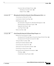
... C-8 Quick Setup By Using the CLI-Based Setup Program D-1 Methods for Accessing the CLI D-2 Accessing the CLI Through Express Setup (Unconfigured Switch Only) D-2 Accessing the CLI Through the Console Port D-3 Taking Out What You Need D-4 Stacking the Switches (Optional) D-5 Connecting to the Console Port D-7 Starting the Terminal Emulation Software D-9 Connecting to a Power Source D-9 Entering the Initial Configuration Information D-10 IP Settings D-10 Completing the Setup Program D-11 78-15136-02 Catalyst 3750 Switch Hardware Installation Guide...
... C-8 Quick Setup By Using the CLI-Based Setup Program D-1 Methods for Accessing the CLI D-2 Accessing the CLI Through Express Setup (Unconfigured Switch Only) D-2 Accessing the CLI Through the Console Port D-3 Taking Out What You Need D-4 Stacking the Switches (Optional) D-5 Connecting to the Console Port D-7 Starting the Terminal Emulation Software D-9 Connecting to a Power Source D-9 Entering the Initial Configuration Information D-10 IP Settings D-10 Completing the Setup Program D-11 78-15136-02 Catalyst 3750 Switch Hardware Installation Guide...
Hardware Installation Guide
Page 14
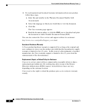
... the Cisco service and support website for as long as its service center will use the product, provided that the fan and power supply warranty is limited to ship a replacement part within ten (10) working days after receipt of the Return Materials Authorization (RMA) request. Catalyst 3750 Switch Hardware Installation Guide xii 78-15136-02 You can vary, depending on the customer location. Enter this part number in...
... the Cisco service and support website for as long as its service center will use the product, provided that the fan and power supply warranty is limited to ship a replacement part within ten (10) working days after receipt of the Return Materials Authorization (RMA) request. Catalyst 3750 Switch Hardware Installation Guide xii 78-15136-02 You can vary, depending on the customer location. Enter this part number in...

Hardware Installation Guide
Page 36
... verify that only the SYST and STAT LEDs are green before entering 10.0.0.1 in the CLI to begin Express Setup. For configuration information for connections to the Ethernet port on the other end of the PC or workstation, as shown Figure 1-5. Catalyst 3750 Switch Hardware Installation Guide 1-8 78-15136-02 Therefore, you can use the mdix auto command in the browser. • Did you...
... verify that only the SYST and STAT LEDs are green before entering 10.0.0.1 in the CLI to begin Express Setup. For configuration information for connections to the Ethernet port on the other end of the PC or workstation, as shown Figure 1-5. Catalyst 3750 Switch Hardware Installation Guide 1-8 78-15136-02 Therefore, you can use the mdix auto command in the browser. • Did you...

Hardware Installation Guide
Page 37
... is configured with an IP address, you assign IP information. The password can start with Express Setup: Step 1 Step 2 Step 3 Step 4 Contact your switch with a number, is a system that connects a network on a different subnet. This identifies the physical location of the switch in the System Contact field. Enter the IP address of the switch. 78-15136-02 Catalyst 3750 Switch Hardware Installation Guide 1-9 Step 5 Step 6 Step 7 Step 8 Step 9 Enter your password...
... is configured with an IP address, you assign IP information. The password can start with Express Setup: Step 1 Step 2 Step 3 Step 4 Contact your switch with a number, is a system that connects a network on a different subnet. This identifies the physical location of the switch in the System Contact field. Enter the IP address of the switch. 78-15136-02 Catalyst 3750 Switch Hardware Installation Guide 1-9 Step 5 Step 6 Step 7 Step 8 Step 9 Enter your password...

Hardware Installation Guide
Page 38
... Password field. (Optional) Click Enable to configure Simple Network Management Protocol (SNMP). b. Verifying Switch IP Address (Optional) After you have installed the switch in your network, follow these steps to manage switches by using Cisco Works or another SNMP-based network-management system. The Telnet password can access and modify MIB objects. Enable SNMP only if you must enter a community string in the Telnet Password field. If you set the SNMP write community, users...
... Password field. (Optional) Click Enable to configure Simple Network Management Protocol (SNMP). b. Verifying Switch IP Address (Optional) After you have installed the switch in your network, follow these steps to manage switches by using Cisco Works or another SNMP-based network-management system. The Telnet password can access and modify MIB objects. Enable SNMP only if you must enter a community string in the Telnet Password field. If you set the SNMP write community, users...

Hardware Installation Guide
Page 40
... menu bar in Figure 1-8 on a wall, or connecting devices to the switch, see Appendix C, "Managing the Switch by using CMS or the CLI. and port-level settings. Other Switch Home Page Features These additional features are available from the switch home page, as Telnet and Extended Ping. • Help Resources-Access Catalyst 3750 documentation. For more information, refer to the switch software configuration guide For CMS requirements, see Chapter 3, "Installation." 1-12 Catalyst 3750 Switch Hardware Installation Guide...
... menu bar in Figure 1-8 on a wall, or connecting devices to the switch, see Appendix C, "Managing the Switch by using CMS or the CLI. and port-level settings. Other Switch Home Page Features These additional features are available from the switch home page, as Telnet and Extended Ping. • Help Resources-Access Catalyst 3750 documentation. For more information, refer to the switch software configuration guide For CMS requirements, see Chapter 3, "Installation." 1-12 Catalyst 3750 Switch Hardware Installation Guide...

Hardware Installation Guide
Page 46
... ports to the switch software configuration guide or the switch command reference. Catalyst 3750 Switch Hardware Installation Guide 2-6 78-15136-02 When connecting the switch to operate in any combination of the attached device and advertises its own capabilities. For configuration information for copper Ethernet connections and configures the interfaces accordingly. You can use the mdix auto command in compliance with IEEE 802.3ab. (The default setting is enabled, the switch detects the required cable type...
... ports to the switch software configuration guide or the switch command reference. Catalyst 3750 Switch Hardware Installation Guide 2-6 78-15136-02 When connecting the switch to operate in any combination of the attached device and advertises its own capabilities. For configuration information for copper Ethernet connections and configures the interfaces accordingly. You can use the mdix auto command in compliance with IEEE 802.3ab. (The default setting is enabled, the switch detects the required cable type...

Hardware Installation Guide
Page 57
... Power System Hardware Installation Guide. For more information on the Cisco RPS 675, refer to the Cisco RPS 300 Redundant Power System Hardware Installation Guide. You can order a kit (part number ACS-DSBUASYN=) containing that can support six external network devices and provides power to a PC by means of network traffic. Console Port You can connect the switch to one failed device at a time. For console port and adapter pinout information, see the "Connector and Cable Specifications...
... Power System Hardware Installation Guide. For more information on the Cisco RPS 675, refer to the Cisco RPS 300 Redundant Power System Hardware Installation Guide. You can order a kit (part number ACS-DSBUASYN=) containing that can support six external network devices and provides power to a PC by means of network traffic. Console Port You can connect the switch to one failed device at a time. For console port and adapter pinout information, see the "Connector and Cable Specifications...
Hardware Installation Guide
Page 58
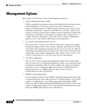
... to the switch software configuration guide on Cisco.com, and the online help for this application. • Cisco IOS command-line interface (CLI) The switch CLI is based on Cisco IOS software and is a graphical user interface that you can use to set of a Simple Network Management Protocol (SNMP) platform. and port-level settings. For more information. • CiscoView application The CiscoView device-management application displays the switch image that can access the...
... to the switch software configuration guide on Cisco.com, and the online help for this application. • Cisco IOS command-line interface (CLI) The switch CLI is based on Cisco IOS software and is a graphical user interface that you can use to set of a Simple Network Management Protocol (SNMP) platform. and port-level settings. For more information. • CiscoView application The CiscoView device-management application displays the switch image that can access the...

Hardware Installation Guide
Page 68
... Terminal to the Console Port To connect a PC to the console port, use the supplied RJ-45-to -DB-25 female DTE adapter. You can order a kit (part number ACS-DSBUASYN=) containing that the switch passes POST. Note If you need to provide a RJ-45-to -DB-9 adapter cable. StackWise cable: 0.5-meter, 1-meter, or 3-meter cable. Verifying Switch Operation Before installing the switch in a rack, on a wall...
... Terminal to the Console Port To connect a PC to the console port, use the supplied RJ-45-to -DB-25 female DTE adapter. You can order a kit (part number ACS-DSBUASYN=) containing that the switch passes POST. Note If you need to provide a RJ-45-to -DB-9 adapter cable. StackWise cable: 0.5-meter, 1-meter, or 3-meter cable. Verifying Switch Operation Before installing the switch in a rack, on a wall...
Hardware Installation Guide
Page 77
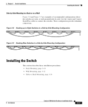
... 78-15136-02 Catalyst 3750 Switch Hardware Installation Guide 3-17 or wall-mounted side-by -Side Mounting Configuration 86825 Figure 3-9 Stacking Nine Switches in a Rack or on a Wall Figure 3-8 and Figure 3-9 are examples of recommended configurations where the switches are rack- Figure 3-8 Stacking up to connect the switches. Use the 1-meter and 3-meter StackWise cables to Eight Switches in a Side-by -side. These...
... 78-15136-02 Catalyst 3750 Switch Hardware Installation Guide 3-17 or wall-mounted side-by -Side Mounting Configuration 86825 Figure 3-9 Stacking Nine Switches in a Rack or on a Wall Figure 3-8 and Figure 3-9 are examples of recommended configurations where the switches are rack- Figure 3-8 Stacking up to connect the switches. Use the 1-meter and 3-meter StackWise cables to Eight Switches in a Side-by -side. These...

Hardware Installation Guide
Page 105
... enabled, the switch detects the required cable type for this feature, refer to a copper 10/100 or 10/100/1000 port on the switch, regardless the type of device on the other end of the cable to an RJ-45 connector on the other end 78-15136-02 Catalyst 3750 Switch Hardware Installation Guide 3-45 The port LED is disabled by default. Therefore, you can use the mdix auto...
... enabled, the switch detects the required cable type for this feature, refer to a copper 10/100 or 10/100/1000 port on the switch, regardless the type of device on the other end of the cable to an RJ-45 connector on the other end 78-15136-02 Catalyst 3750 Switch Hardware Installation Guide 3-45 The port LED is disabled by default. Therefore, you can use the mdix auto...
Hardware Installation Guide
Page 111
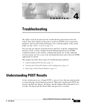
CH A P T E R 4 Troubleshooting The LEDs on self-test (POST), port-connectivity problems, and overall switch performance. This chapter describes these topics for 2 seconds. 78-15136-02 Catalyst 3750 Switch Hardware Installation Guide 4-1 When the switch begins POST, the System, the RPS, the Master, the Status, and the Duplex LEDs turn green for troubleshooting problems: • Understanding POST Results, page 4-1 • Clearing the Switch IP Address and Configuration, page 4-2 • Replacing a Failed Stack Member...
CH A P T E R 4 Troubleshooting The LEDs on self-test (POST), port-connectivity problems, and overall switch performance. This chapter describes these topics for 2 seconds. 78-15136-02 Catalyst 3750 Switch Hardware Installation Guide 4-1 When the switch begins POST, the System, the RPS, the Master, the Status, and the Duplex LEDs turn green for troubleshooting problems: • Understanding POST Results, page 4-1 • Clearing the Switch IP Address and Configuration, page 4-2 • Replacing a Failed Stack Member...

Hardware Installation Guide
Page 125
... and Cable Specifications This appendix describes the Catalyst 3750 switch ports and the cables and adapters that you use to connect the switch to enable the automatic crossover feature. Figure B-1 shows the pinout. When the automatic crossover feature is disabled by default. Note On switches running Cisco IOS Release 12.1(14)EA1 or later, you can use either a crossover or a straight-through cable for connections to the switch software configuration guide...
... and Cable Specifications This appendix describes the Catalyst 3750 switch ports and the cables and adapters that you use to connect the switch to enable the automatic crossover feature. Figure B-1 shows the pinout. When the automatic crossover feature is disabled by default. Note On switches running Cisco IOS Release 12.1(14)EA1 or later, you can use either a crossover or a straight-through cable for connections to the switch software configuration guide...

Hardware Installation Guide
Page 127
... and Cable Specifications Connector Specifications Figure B-1 10/100/1000 Port Pinouts Pin Label 1 TP0+ 2 TP0- 3 TP1+ 4 TP2+ 5 TP2- 6 TP1- 7 TP3+ 8 TP3- 12345678 10/100 Ports The 10/100 Ethernet ports use the mdix auto command in the port name. When the automatic crossover feature is disabled by an X in the CLI to the switch software configuration guide or the switch command reference. 78-15136-02 Catalyst 3750 Switch Hardware Installation Guide...
... and Cable Specifications Connector Specifications Figure B-1 10/100/1000 Port Pinouts Pin Label 1 TP0+ 2 TP0- 3 TP1+ 4 TP2+ 5 TP2- 6 TP1- 7 TP3+ 8 TP3- 12345678 10/100 Ports The 10/100 Ethernet ports use the mdix auto command in the port name. When the automatic crossover feature is disabled by an X in the CLI to the switch software configuration guide or the switch command reference. 78-15136-02 Catalyst 3750 Switch Hardware Installation Guide...

Hardware Installation Guide
Page 133
... Cable Specifications Cable and Adapter Specifications Crossover Cable and Adapter Pinouts This section describes how to the switch software configuration guide or the switch command reference. 78-15136-02 Catalyst 3750 Switch Hardware Installation Guide B-9 The wire connected to the pin on the outside of the left plug should be the same color as the wire connected to a copper 10/100 or 10/100/1000 port on the switch, regardless the type...
... Cable Specifications Cable and Adapter Specifications Crossover Cable and Adapter Pinouts This section describes how to the switch software configuration guide or the switch command reference. 78-15136-02 Catalyst 3750 Switch Hardware Installation Guide B-9 The wire connected to the pin on the outside of the left plug should be the same color as the wire connected to a copper 10/100 or 10/100/1000 port on the switch, regardless the type...
Hardware Installation Guide
Page 143
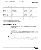
..., follow the instructions in the README_FIRST.txt file to access and run the Java-based CMS: • Java plug-in 1.4 • Java plug-in 1.3.1 These Java plug-ins are supported both in . 78-15136-02 Catalyst 3750 Switch Hardware Installation Guide C-7 Service Pack 1 or higher is not supported. 2. Appendix C Managing the Switch by Using the Cluster Management Suite CMS Requirements Table C-2 Supported Operating Systems and...
..., follow the instructions in the README_FIRST.txt file to access and run the Java-based CMS: • Java plug-in 1.4 • Java plug-in 1.3.1 These Java plug-ins are supported both in . 78-15136-02 Catalyst 3750 Switch Hardware Installation Guide C-7 Service Pack 1 or higher is not supported. 2. Appendix C Managing the Switch by Using the Cluster Management Suite CMS Requirements Table C-2 Supported Operating Systems and...

Hardware Installation Guide
Page 154
... the switch to configure and manage the switch. This information is powered up the switch, you complete the setup program: • Switch IP address • Subnet mask (IP netmask) • Default gateway (router) • Enable secret password • Enable password • Telnet password D-10 Catalyst 3750 Switch Hardware Installation Guide 78-15136-02 If POST fails, see Chapter 4, "Troubleshooting," to determine a course of tests that run automatically to ensure that shipped with your network...
... the switch to configure and manage the switch. This information is powered up the switch, you complete the setup program: • Switch IP address • Subnet mask (IP netmask) • Default gateway (router) • Enable secret password • Enable password • Telnet password D-10 Catalyst 3750 Switch Hardware Installation Guide 78-15136-02 If POST fails, see Chapter 4, "Troubleshooting," to determine a course of tests that run automatically to ensure that shipped with your network...

Hardware Installation Guide
Page 196
... ports 2-15 straight-through cable pinout four twisted-pair 10/100 ports B-7 four twisted-pair 1000BASE-T ports B-8 two twisted-pair 10/100 ports B-6 SunNet Manager 2-18 switch installation warning E-25 switch powering on 3-10 system LED 2-9 T table-mounting 3-36 technical specifications A-1 telco racks 3-18 Telnet, and accessing the CLI 2-18 temperature, operating A-1 terminal, connecting to switch 3-9 terminal emulation software 3-8, D-9 translated warnings E-1 to E-31 IN-6 Catalyst 3750 Switch Hardware Installation Guide...
... ports 2-15 straight-through cable pinout four twisted-pair 10/100 ports B-7 four twisted-pair 1000BASE-T ports B-8 two twisted-pair 10/100 ports B-6 SunNet Manager 2-18 switch installation warning E-25 switch powering on 3-10 system LED 2-9 T table-mounting 3-36 technical specifications A-1 telco racks 3-18 Telnet, and accessing the CLI 2-18 temperature, operating A-1 terminal, connecting to switch 3-9 terminal emulation software 3-8, D-9 translated warnings E-1 to E-31 IN-6 Catalyst 3750 Switch Hardware Installation Guide...


