Installation Guide
Page 4
...the Switch 3-1 Installation Process 3-2 Rack-Mounting Guidelines 3-2 Unpacking the Switch 3-4 Installing the Switch in a Rack 3-4 Required Installation Tools 3-4 Installing the Catalyst 4500 E-Series Switches in a Rack 3-5 Establishing the System Ground Connection 3-7 Required Tools and Parts 3-8 Connecting System Ground 3-8 Completing the Installation Process ...Tools 4-8 Removing a DC-Input Power Supply 4-8 Installing a DC-Input Power Supply 4-11 Removing and Installing the Chassis Fan Tray Assembly 4-13 Required Tools 4-13 Removing the Fan Tray Assembly 4-13 Installing the Fan Tray Assembly 4-...
...the Switch 3-1 Installation Process 3-2 Rack-Mounting Guidelines 3-2 Unpacking the Switch 3-4 Installing the Switch in a Rack 3-4 Required Installation Tools 3-4 Installing the Catalyst 4500 E-Series Switches in a Rack 3-5 Establishing the System Ground Connection 3-7 Required Tools and Parts 3-8 Connecting System Ground 3-8 Completing the Installation Process ...Tools 4-8 Removing a DC-Input Power Supply 4-8 Installing a DC-Input Power Supply 4-11 Removing and Installing the Chassis Fan Tray Assembly 4-13 Required Tools 4-13 Removing the Fan Tray Assembly 4-13 Installing the Fan Tray Assembly 4-...
Installation Guide
Page 9
... illustrations and specification tables for the supported AC power cords. The chapter also contains illustrations of the chassis. OL-13972-02 Catalyst 4500 E-Series Switches Installation Guide vii Installing the Switch Describes how to obtain related documentation and technical ...assistance. Illustrations and specification tables are also provided for the available Catalyst 4500 E-series switch AC-input and DC-input power supplies. Audience This guide is organized as follows: Chapter Chapter 1 ...
... illustrations and specification tables for the supported AC power cords. The chapter also contains illustrations of the chassis. OL-13972-02 Catalyst 4500 E-Series Switches Installation Guide vii Installing the Switch Describes how to obtain related documentation and technical ...assistance. Illustrations and specification tables are also provided for the available Catalyst 4500 E-series switch AC-input and DC-input power supplies. Audience This guide is organized as follows: Chapter Chapter 1 ...
Installation Guide
Page 10
... OL-13972-02 Alternative keywords are in angle brackets. A nonquoted set of features and interfaces, refer to the software configuration guide for your Catalyst 4500 E-series switch in the event that could result in equipment damage or loss of data. Notes contain helpful suggestions or references to the... factory. Terminal sessions and information the system displays are in italic screen font. Arguments for which you need to move the chassis or have to return it to material not covered in boldface. Arguments for which you supply values are in screen font. Do not ...
... OL-13972-02 Alternative keywords are in angle brackets. A nonquoted set of features and interfaces, refer to the software configuration guide for your Catalyst 4500 E-series switch in the event that could result in equipment damage or loss of data. Notes contain helpful suggestions or references to the... factory. Terminal sessions and information the system displays are in italic screen font. Arguments for which you need to move the chassis or have to return it to material not covered in boldface. Arguments for which you supply values are in screen font. Do not ...

Installation Guide
Page 20
... redundant power supplies, a single supervisor engine, and slots for up to two modules. Catalyst 4500 E-Series Switches Installation Guide 1-2 OL-13972-02 Figure 1-1 shows a front view of the Catalyst 4503-E switch chassis. Figure 1-1 Catalyst 4503-E Switch Chassis (Front View) 4 3 2 RESMYSOTVEEMLGARBOELUNFODR 4503 MinimumVeCrastio45n0: 0IOSSo:f1tw2a.2r(e37R)eSqGuirement 231362 1 1 Fan tray assembly 2 Switching modules (slots 2 and...
... redundant power supplies, a single supervisor engine, and slots for up to two modules. Catalyst 4500 E-Series Switches Installation Guide 1-2 OL-13972-02 Figure 1-1 shows a front view of the Catalyst 4503-E switch chassis. Figure 1-1 Catalyst 4503-E Switch Chassis (Front View) 4 3 2 RESMYSOTVEEMLGARBOELUNFODR 4503 MinimumVeCrastio45n0: 0IOSSo:f1tw2a.2r(e37R)eSqGuirement 231362 1 1 Fan tray assembly 2 Switching modules (slots 2 and...
Installation Guide
Page 21
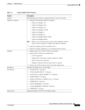
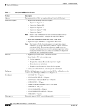
...engine redundancy is not supported in this chassis. Have chassis slot restrictions - Require a specific software release level to support the supervisor engines. Slots are numbered from 1 (top) to two Catalyst 4500 series modules. • Some Catalyst 4500 series modules may: - Not be... Engine IV - Supervisor Engine II-Plus-TS - Supervisor Engine 6-E - Chapter 1 Product Overview Catalyst 4503-E Switch Table 1-1 Catalyst 4503-E Switch Features Feature Chassis Supervisor engines Description Three horizontal slots. Supervisor Engine 7-E - Supervisor Engine V-10GE -
...engine redundancy is not supported in this chassis. Have chassis slot restrictions - Require a specific software release level to support the supervisor engines. Slots are numbered from 1 (top) to two Catalyst 4500 series modules. • Some Catalyst 4500 series modules may: - Not be... Engine IV - Supervisor Engine II-Plus-TS - Supervisor Engine 6-E - Chapter 1 Product Overview Catalyst 4503-E Switch Table 1-1 Catalyst 4503-E Switch Features Feature Chassis Supervisor engines Description Three horizontal slots. Supervisor Engine 7-E - Supervisor Engine V-10GE -
Installation Guide
Page 22
... requirements can be configured with integrated PEM (PWR-C45-1400DC-P) - Catalyst 4500 E-Series Switches Installation Guide 1-4 OL-13972-02 External AC power shelf (WS-P4502-1PSU) • All Catalyst 4500 series AC-input power supplies require single-phase source AC. Source...the fan tray front panel) - One fan tray model is available: - WS-X4593-E • The fan tray contains six individual fans. Catalyst 4503-E Switch Chapter 1 Product Overview Table 1-1 Catalyst 4503-E Switch Features (continued) Feature Inline power Fan tray Power supply Description Integrated...
... requirements can be configured with integrated PEM (PWR-C45-1400DC-P) - Catalyst 4500 E-Series Switches Installation Guide 1-4 OL-13972-02 External AC power shelf (WS-P4502-1PSU) • All Catalyst 4500 series AC-input power supplies require single-phase source AC. Source...the fan tray front panel) - One fan tray model is available: - WS-X4593-E • The fan tray contains six individual fans. Catalyst 4503-E Switch Chapter 1 Product Overview Table 1-1 Catalyst 4503-E Switch Features (continued) Feature Inline power Fan tray Power supply Description Integrated...
Installation Guide
Page 23
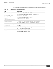
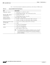
Table 1-2 Catalyst 4503-E Switch Specifications Item Temperature, ambient Humidity (RH), ambient (noncondensing) Altitude, operating and nonoperating Sound pressure level Dimensions (H x W x D) and rack units (RU) Weight Airflow Specification &#...; 32.25 lbs (14.63 kg) minimum weight • 75 lbs (34 kg) maximum weight • Chassis fan tray: Right to left • Power supply fan: Front to back OL-13972-02 Catalyst 4500 E-Series Switches Installation Guide 1-5 Chapter 1 Product Overview Catalyst 4503-E Switch Table 1-2 lists the environmental and physical specifications of the...
Table 1-2 Catalyst 4503-E Switch Specifications Item Temperature, ambient Humidity (RH), ambient (noncondensing) Altitude, operating and nonoperating Sound pressure level Dimensions (H x W x D) and rack units (RU) Weight Airflow Specification &#...; 32.25 lbs (14.63 kg) minimum weight • 75 lbs (34 kg) maximum weight • Chassis fan tray: Right to left • Power supply fan: Front to back OL-13972-02 Catalyst 4500 E-Series Switches Installation Guide 1-5 Chapter 1 Product Overview Catalyst 4503-E Switch Table 1-2 lists the environmental and physical specifications of the...

Installation Guide
Page 24
... E-Series Switches Installation Guide 1-6 OL-13972-02 Figure 1-2 shows a front view of the Catalyst 4506-E switch chassis. Catalyst 4506-E Switch Chapter 1 Product Overview Catalyst 4506-E Switch The Catalyst 4506-E switch is a 6-slot horizontal chassis supporting redundant power supplies, redundant supervisor engines, and slots for up to 6) 3 Supervisor engine (slot 1) 4 Power supplies Table 1-3 describes the features of...
... E-Series Switches Installation Guide 1-6 OL-13972-02 Figure 1-2 shows a front view of the Catalyst 4506-E switch chassis. Catalyst 4506-E Switch Chapter 1 Product Overview Catalyst 4506-E Switch The Catalyst 4506-E switch is a 6-slot horizontal chassis supporting redundant power supplies, redundant supervisor engines, and slots for up to 6) 3 Supervisor engine (slot 1) 4 Power supplies Table 1-3 describes the features of...
Installation Guide
Page 25
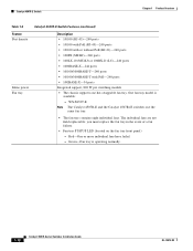
... the minimum software release versions required to five Catalyst 4500 series modules. • Some Catalyst 4500 series modules may: - Not be installed in slot 1. • Supervisor engine redundancy is not supported in this chassis. • Supports up to support the supervisor...PoE-240 ports • 10GBASE-X-32 ports Integrated support, 820 W per switching module OL-13972-02 Catalyst 4500 E-Series Switches Installation Guide 1-7 Supervisor Engine II-Plus-10GE - Have chassis slot restrictions - Require a specific software release level to 6 (bottom). • Supports the following ...
... the minimum software release versions required to five Catalyst 4500 series modules. • Some Catalyst 4500 series modules may: - Not be installed in slot 1. • Supervisor engine redundancy is not supported in this chassis. • Supports up to support the supervisor...PoE-240 ports • 10GBASE-X-32 ports Integrated support, 820 W per switching module OL-13972-02 Catalyst 4500 E-Series Switches Installation Guide 1-7 Supervisor Engine II-Plus-10GE - Have chassis slot restrictions - Require a specific software release level to 6 (bottom). • Supports the following ...
Installation Guide
Page 26
... power supplies or multiple AC-power plugs on the fan tray front panel) - Catalyst 4506-E Switch Chapter 1 Product Overview Table 1-3 Catalyst 4506-E Switch Features (continued) Feature Fan tray Power supply Description • The chassis supports one or two power supplies. WS-X4596-E • The fan tray contains four individual fans. External AC power shelf...
... power supplies or multiple AC-power plugs on the fan tray front panel) - Catalyst 4506-E Switch Chapter 1 Product Overview Table 1-3 Catalyst 4506-E Switch Features (continued) Feature Fan tray Power supply Description • The chassis supports one or two power supplies. WS-X4596-E • The fan tray contains four individual fans. External AC power shelf...
Installation Guide
Page 27
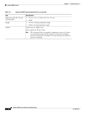
...-E Switch Table 1-4 lists the environmental and physical specifications of 12 inches (30.5 cm) between two chassis to prevent overheating. Table 1-4 Catalyst 4506-E Switch Specifications Item Temperature, ambient Humidity (RH), ambient (noncondensing) Altitude, operating and nonoperating Sound pressure level Dimensions (H x W x D) and ...31.70 cm) • 10 RU • 34.5 lbs (15.6 kg) minimum weight • 100 lbs (45.4 kg) maximum weight • Chassis fan tray: Right to left • Power supply fan: Front to back Note We recommend that you maintain a minimum air space of 6 inches (16 ...
...-E Switch Table 1-4 lists the environmental and physical specifications of 12 inches (30.5 cm) between two chassis to prevent overheating. Table 1-4 Catalyst 4506-E Switch Specifications Item Temperature, ambient Humidity (RH), ambient (noncondensing) Altitude, operating and nonoperating Sound pressure level Dimensions (H x W x D) and ...31.70 cm) • 10 RU • 34.5 lbs (15.6 kg) minimum weight • 100 lbs (45.4 kg) maximum weight • Chassis fan tray: Right to left • Power supply fan: Front to back Note We recommend that you maintain a minimum air space of 6 inches (16 ...

Installation Guide
Page 28
... Chapter 1 Product Overview Catalyst 4507R-E Switch The Catalyst 4507R-E switch is a 7-slot horizontal chassis supporting redundant power supplies, redundant supervisor engines, and slots for up to six modules. Figure 1-3 shows a front view of the Catalyst 4507R-E switch. 1-10 Catalyst 4500 E-Series Switches Installation Guide OL-13972-02 Figure 1-3 Catalyst 4507R-E Switch (Front View) 4 RESMYSOTVEEMLGARBOELUNFODR 4506 MinimumVeCrastio45n0...
... Chapter 1 Product Overview Catalyst 4507R-E Switch The Catalyst 4507R-E switch is a 7-slot horizontal chassis supporting redundant power supplies, redundant supervisor engines, and slots for up to six modules. Figure 1-3 shows a front view of the Catalyst 4507R-E switch. 1-10 Catalyst 4500 E-Series Switches Installation Guide OL-13972-02 Figure 1-3 Catalyst 4507R-E Switch (Front View) 4 RESMYSOTVEEMLGARBOELUNFODR 4506 MinimumVeCrastio45n0...
Installation Guide
Page 29
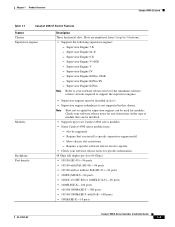
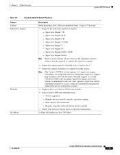
Supervisor Engine II-Plus-10GE - Redundant supervisor engines help minimize network downtime. Have chassis slot restrictions - Chapter 1 Product Overview Catalyst 4507R-E Switch Table 1-5 Catalyst 4507R-E Switch Features Feature Chassis Supervisor engines Description Seven horizontal slots. Supervisor Engine 6-E - Note The Catalyst 4507R-E switch supports 1+1 supervisor-engine redundancy for specific information. 24 Gbps full duplex per slot (240...
Supervisor Engine II-Plus-10GE - Redundant supervisor engines help minimize network downtime. Have chassis slot restrictions - Chapter 1 Product Overview Catalyst 4507R-E Switch Table 1-5 Catalyst 4507R-E Switch Features Feature Chassis Supervisor engines Description Seven horizontal slots. Supervisor Engine 6-E - Note The Catalyst 4507R-E switch supports 1+1 supervisor-engine redundancy for specific information. 24 Gbps full duplex per slot (240...
Installation Guide
Page 30
...-T with PoE-240 ports • 10GBASE-X-34 ports Integrated support, 820 W per switching module • The chassis supports one hot-swappable fan tray. Green-Fan tray is available: - WS-X4597-E Note The Catalyst 4507R-E and the Catalyst 4507R+E switches use the same fan tray. • The fan tray contains eight individual fans. The individual...
...-T with PoE-240 ports • 10GBASE-X-34 ports Integrated support, 820 W per switching module • The chassis supports one hot-swappable fan tray. Green-Fan tray is available: - WS-X4597-E Note The Catalyst 4507R-E and the Catalyst 4507R+E switches use the same fan tray. • The fan tray contains eight individual fans. The individual...
Installation Guide
Page 32
... to left Power supply fan: Front to back Note We recommend that you maintain a minimum air space of 6 inches (16 cm) between walls and the chassis air vents and a minimum horizontal separation of 12 inches (30.5 cm) between two chassis to prevent overheating. 1-14 Catalyst 4500 E-Series Switches Installation Guide OL-13972-02
... to left Power supply fan: Front to back Note We recommend that you maintain a minimum air space of 6 inches (16 cm) between walls and the chassis air vents and a minimum horizontal separation of 12 inches (30.5 cm) between two chassis to prevent overheating. 1-14 Catalyst 4500 E-Series Switches Installation Guide OL-13972-02

Installation Guide
Page 33
... E-Series Switches Installation Guide 1-15 Figure 1-4 Catalyst 4510R-E Switch Chassis (Front View) 4 RESMYSOTVEEMLGARBOELUNFODR 4506 MinimumVeCrastio45n0: 0IOSSo:f1tw2a.2r(e37R)eSqGuirement 3 2 1 STATUS STATUS 12 12 34 5 6 34 5 6 7 7 ...6) 4 Power supplies Table 1-7 describes the features of the Catalyst 4510R-E switch with the chassis major features identified. Chapter 1 Product Overview Catalyst 4510R-E Switch Catalyst 4510R-E Switch The Catalyst 4510R-E switch is a 10-slot horizontal chassis supporting redundant power supplies, redundant supervisor engines, and slots for ...
... E-Series Switches Installation Guide 1-15 Figure 1-4 Catalyst 4510R-E Switch Chassis (Front View) 4 RESMYSOTVEEMLGARBOELUNFODR 4506 MinimumVeCrastio45n0: 0IOSSo:f1tw2a.2r(e37R)eSqGuirement 3 2 1 STATUS STATUS 12 12 34 5 6 34 5 6 7 7 ...6) 4 Power supplies Table 1-7 describes the features of the Catalyst 4510R-E switch with the chassis major features identified. Chapter 1 Product Overview Catalyst 4510R-E Switch Catalyst 4510R-E Switch The Catalyst 4510R-E switch is a 10-slot horizontal chassis supporting redundant power supplies, redundant supervisor engines, and slots for ...
Installation Guide
Page 34
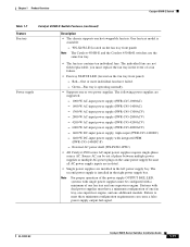
... your software release notes for integrated resiliency. Not be installed in slot 3 or in slot 4. • Supervisor engine redundancy is supported in this chassis. Supervisor Engine 7-E - Note The Catalyst 4510R-E switch supports 1+1 supervisor-engine redundancy for specific information. 24 Gbps full duplex per slot on five slots, plus 12 Gbps full duplex...
... your software release notes for integrated resiliency. Not be installed in slot 3 or in slot 4. • Supervisor engine redundancy is supported in this chassis. Supervisor Engine 7-E - Note The Catalyst 4510R-E switch supports 1+1 supervisor-engine redundancy for specific information. 24 Gbps full duplex per slot on five slots, plus 12 Gbps full duplex...
Installation Guide
Page 35
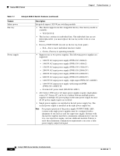
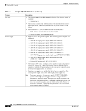
...contains ten individual fans. you must have failed. - External AC power shelf (WS-P4502-1PSU) • All Catalyst 4500 series AC-input power supplies require single-phase source AC. OL-13972-02 Catalyst 4500 E-Series Switches Installation Guide 1-17 The individual fans are installed in the left... LED, systems with integrated PEM (PWR-C45-1400DC-P) - One fan tray model is available: - Chapter 1 Product Overview Catalyst 4510R-E Switch Table 1-7 Catalyst 4510R-E Switch Features (continued) Feature Fan tray Description • The chassis supports one supervisor engine.
...contains ten individual fans. you must have failed. - External AC power shelf (WS-P4502-1PSU) • All Catalyst 4500 series AC-input power supplies require single-phase source AC. OL-13972-02 Catalyst 4500 E-Series Switches Installation Guide 1-17 The individual fans are installed in the left... LED, systems with integrated PEM (PWR-C45-1400DC-P) - One fan tray model is available: - Chapter 1 Product Overview Catalyst 4510R-E Switch Table 1-7 Catalyst 4510R-E Switch Features (continued) Feature Fan tray Description • The chassis supports one supervisor engine.
Installation Guide
Page 36
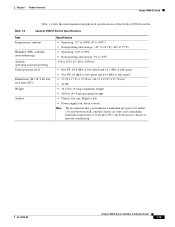
... We recommend that you maintain a minimum air space of 6 inches (16 cm) between walls and the chassis air vents and a minimum horizontal separation of the Catalyst 4510R-E switch. Table 1-8 Catalyst 4510R-E Switch Specifications Item Temperature, ambient Humidity (RH), ambient (noncondensing) Altitude, operating Sound pressure level Dimensions...; 14 RU • 54.5 lbs (24.77 kg) minimum • 108 lbs (45.4 kg) maximum • Chassis fan tray: Right to left • Power supply fan: Front to prevent overheating. 1-18 Catalyst 4500 E-Series Switches Installation Guide OL-13972-02
... We recommend that you maintain a minimum air space of 6 inches (16 cm) between walls and the chassis air vents and a minimum horizontal separation of the Catalyst 4510R-E switch. Table 1-8 Catalyst 4510R-E Switch Specifications Item Temperature, ambient Humidity (RH), ambient (noncondensing) Altitude, operating Sound pressure level Dimensions...; 14 RU • 54.5 lbs (24.77 kg) minimum • 108 lbs (45.4 kg) maximum • Chassis fan tray: Right to left • Power supply fan: Front to prevent overheating. 1-18 Catalyst 4500 E-Series Switches Installation Guide OL-13972-02
Installation Guide
Page 65
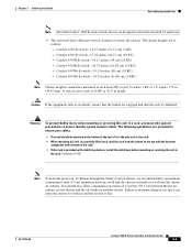
....13 cm) (10 RU) - Failure to maintain adequate air space can cause the chassis to overheat and the system to insert the chassis. OL-13972-02 Catalyst 4500 E-Series Switches Installation Guide 3-3 Catalyst 4510R-E switch-24.35 inches (61.84 cm) (14 RU) - You should ... a minimum 6-inch (15 cm) separation between the hot air exhaust on one chassis and the air intake on another chassis. Statement 1006 Note To maintain proper air circulation through the Catalyst switch chassis, we recommend that you must have sufficient vertical clearance to fail. Chapter 3 Installing...
....13 cm) (10 RU) - Failure to maintain adequate air space can cause the chassis to overheat and the system to insert the chassis. OL-13972-02 Catalyst 4500 E-Series Switches Installation Guide 3-3 Catalyst 4510R-E switch-24.35 inches (61.84 cm) (14 RU) - You should ... a minimum 6-inch (15 cm) separation between the hot air exhaust on one chassis and the air intake on another chassis. Statement 1006 Note To maintain proper air circulation through the Catalyst switch chassis, we recommend that you must have sufficient vertical clearance to fail. Chapter 3 Installing...

