Installation Guide
Page 21
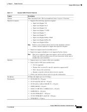
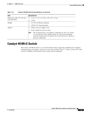
...Switch Features Feature Chassis Supervisor engines Description Three horizontal slots. Supervisor Engine 6-E - Supervisor Engine V-10GE - Supervisor Engine II-Plus-10GE - Note Slots not occupied by supervisor engines can be installed. • Supports up to your software release notes for specific information. 48 Gbps full duplex per slot (96 Gbps) • 10.../100 (RJ-45)-96 ports • 10/100 with PoE (RJ-45)-96 ports • 10/100 with or without PoE (RJ-21)-96 ports • 100FX...
...Switch Features Feature Chassis Supervisor engines Description Three horizontal slots. Supervisor Engine 6-E - Supervisor Engine V-10GE - Supervisor Engine II-Plus-10GE - Note Slots not occupied by supervisor engines can be installed. • Supports up to your software release notes for specific information. 48 Gbps full duplex per slot (96 Gbps) • 10.../100 (RJ-45)-96 ports • 10/100 with PoE (RJ-45)-96 ports • 10/100 with or without PoE (RJ-21)-96 ports • 100FX...
Installation Guide
Page 25
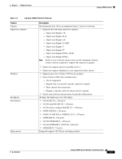
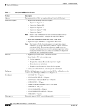
...: - Chapter 1 Product Overview Catalyst 4506-E Switch Table 1-3 Catalyst 4506-E Switch Features Feature Chassis Supervisor engines Description Six horizontal slots. Slots are numbered from 1 (top) to operate • Check your software release notes for specific information. 48 Gbps full duplex per slot (240 Gbps) • 10/100 (RJ-45)-240 ports • 10/100 with PoE (RJ-45...
...: - Chapter 1 Product Overview Catalyst 4506-E Switch Table 1-3 Catalyst 4506-E Switch Features Feature Chassis Supervisor engines Description Six horizontal slots. Slots are numbered from 1 (top) to operate • Check your software release notes for specific information. 48 Gbps full duplex per slot (240 Gbps) • 10/100 (RJ-45)-240 ports • 10/100 with PoE (RJ-45...

Installation Guide
Page 28
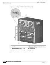
Figure 1-3 shows a front view of the Catalyst 4507R-E switch. 1-10 Catalyst 4500 E-Series Switches Installation Guide OL-13972-02 Catalyst 4507R-E Switch Chapter 1 Product Overview Catalyst 4507R-E Switch The Catalyst 4507R-E switch is a 7-slot horizontal chassis supporting redundant power supplies, redundant supervisor engines, and slots for up to six modules. Figure 1-3 Catalyst 4507R-E Switch (Front View) 4 RESMYSOTVEEMLGARBOELUNFODR 4506 MinimumVeCrastio45n0: 0IOSSo...
Figure 1-3 shows a front view of the Catalyst 4507R-E switch. 1-10 Catalyst 4500 E-Series Switches Installation Guide OL-13972-02 Catalyst 4507R-E Switch Chapter 1 Product Overview Catalyst 4507R-E Switch The Catalyst 4507R-E switch is a 7-slot horizontal chassis supporting redundant power supplies, redundant supervisor engines, and slots for up to six modules. Figure 1-3 Catalyst 4507R-E Switch (Front View) 4 RESMYSOTVEEMLGARBOELUNFODR 4506 MinimumVeCrastio45n0: 0IOSSo...

Installation Guide
Page 33
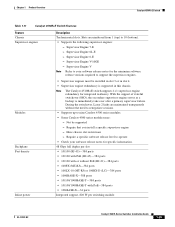
... 46 47 48 1 2 231953 1 Fan tray assembly 2 Switching modules (slots 1-4 and 7-10) 3 Supervisor engines (primary in slot 5 and secondary in slot 6) 4 Power supplies Table 1-7 describes the features of the Catalyst 4510R-E switch with the chassis major features identified. Chapter 1 Product Overview Catalyst 4510R-E Switch Catalyst 4510R-E Switch The Catalyst 4510R-E switch is a 10-slot horizontal chassis supporting redundant power supplies, redundant...
... 46 47 48 1 2 231953 1 Fan tray assembly 2 Switching modules (slots 1-4 and 7-10) 3 Supervisor engines (primary in slot 5 and secondary in slot 6) 4 Power supplies Table 1-7 describes the features of the Catalyst 4510R-E switch with the chassis major features identified. Chapter 1 Product Overview Catalyst 4510R-E Switch Catalyst 4510R-E Switch The Catalyst 4510R-E switch is a 10-slot horizontal chassis supporting redundant power supplies, redundant...
Installation Guide
Page 34
... to immediately take over after a primary supervisor failure. Have chassis slot restrictions - Supervisor Engine V-10GE - Supervisor Engine 7-E - Require a specific software release level to 10 (bottom). • Supports the following supervisor engines: - Note The Catalyst 4510R-E switch supports 1+1 supervisor-engine redundancy for integrated resiliency. Slots are maintained transparently without PoE (RJ-21)-384 ports •...
... to immediately take over after a primary supervisor failure. Have chassis slot restrictions - Supervisor Engine V-10GE - Supervisor Engine 7-E - Require a specific software release level to 10 (bottom). • Supports the following supervisor engines: - Note The Catalyst 4510R-E switch supports 1+1 supervisor-engine redundancy for integrated resiliency. Slots are maintained transparently without PoE (RJ-21)-384 ports •...
Installation Guide
Page 41
... of 6 inches (16 cm) between walls and the chassis air vents and a minimum horizontal separation of the Catalyst 4510R+E switch with the chassis major features identified. OL-13972-02 Catalyst 4500 E-Series Switches Installation Guide 1-23 Catalyst 4510R+E Switch The Catalyst 4510R+E switch is a 10-slot horizontal chassis supporting redundant power supplies, redundant supervisor engines, and...
... of 6 inches (16 cm) between walls and the chassis air vents and a minimum horizontal separation of the Catalyst 4510R+E switch with the chassis major features identified. OL-13972-02 Catalyst 4500 E-Series Switches Installation Guide 1-23 Catalyst 4510R+E Switch The Catalyst 4510R+E switch is a 10-slot horizontal chassis supporting redundant power supplies, redundant supervisor engines, and...
Installation Guide
Page 42
Catalyst 4510R+E Switch Figure 1-6 Catalyst 4510R+E Switch Chassis (Front View) Chapter 1 Product Overview +E Series 4 +E Series RESMYSOTVEEMLGARBOELUNFODR 4506 MinimumVeCrastio45n0: 0IOSSo:f1tw2a.2r(e37R)eSqGuirement 3 2 1 STATUS STATUS 12 12 34 5 6 34 5 6 78 78 9 10 9 10 11 12 13 14 15 16 10E/1T0H0EBRANSEET-TX 17 18 11 ... 42 43 44 45 46 47 48 43 44 45 46 47 48 1 2 279247 1 Fan tray 2 Switching modules (slots 1-4, 7-10) 3 Supervisor engines (primary in slot 5 and secondary in slot 6) 4 Power supplies Table 1-11 describes the features of the Catalyst 4510R...
Catalyst 4510R+E Switch Figure 1-6 Catalyst 4510R+E Switch Chassis (Front View) Chapter 1 Product Overview +E Series 4 +E Series RESMYSOTVEEMLGARBOELUNFODR 4506 MinimumVeCrastio45n0: 0IOSSo:f1tw2a.2r(e37R)eSqGuirement 3 2 1 STATUS STATUS 12 12 34 5 6 34 5 6 78 78 9 10 9 10 11 12 13 14 15 16 10E/1T0H0EBRANSEET-TX 17 18 11 ... 42 43 44 45 46 47 48 43 44 45 46 47 48 1 2 279247 1 Fan tray 2 Switching modules (slots 1-4, 7-10) 3 Supervisor engines (primary in slot 5 and secondary in slot 6) 4 Power supplies Table 1-11 describes the features of the Catalyst 4510R...
Installation Guide
Page 43
... engine - Supervisor Engine 6-E - Note The Catalyst 4510R+E switch supports 1+1 supervisor engine redundancy for specific information. 48 Gbps full duplex per slot • 10/100 (RJ-45)-384 ports • 10/100 with PoE (RJ-45)-384 ports • 10/100 with PoE-384 ports • 10GBASE-X-34 ports Integrated... support, 820 W per switching module OL-13972-02 Catalyst 4500 E-Series Switches Installation Guide 1-25 Not...
... engine - Supervisor Engine 6-E - Note The Catalyst 4510R+E switch supports 1+1 supervisor engine redundancy for specific information. 48 Gbps full duplex per slot • 10/100 (RJ-45)-384 ports • 10/100 with PoE (RJ-45)-384 ports • 10/100 with PoE-384 ports • 10GBASE-X-34 ports Integrated... support, 820 W per switching module OL-13972-02 Catalyst 4500 E-Series Switches Installation Guide 1-25 Not...
Installation Guide
Page 50
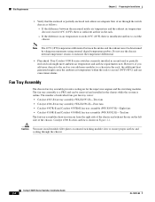
...;C (18°F) temperature differential between the measured intake air temperature and the exhaust air temperature does not exceed 10°C (18°F), there is sufficient airflow in the chassis while the system is a FRU and can cause minor alarms. Fan Tray Assembly The ...-E)-Eight fans • Catalyst 4510R-E and Catalyst 4510R+E fan tray assembly (WS-X4582-E)-Ten fans The fan tray assemblies draw in room air from the right side of the chassis and exhaust the air on unused switching module slots to measure the temperature differential. • Plan ahead. Caution You must be removed...
...;C (18°F) temperature differential between the measured intake air temperature and the exhaust air temperature does not exceed 10°C (18°F), there is sufficient airflow in the chassis while the system is a FRU and can cause minor alarms. Fan Tray Assembly The ...-E)-Eight fans • Catalyst 4510R-E and Catalyst 4510R+E fan tray assembly (WS-X4582-E)-Ten fans The fan tray assemblies draw in room air from the right side of the chassis and exhaust the air on unused switching module slots to measure the temperature differential. • Plan ahead. Caution You must be removed...

Installation Guide
Page 52
...Radio frequencies emanating from a person's fingers or prolonged exposure to appear on all chassis slots are covered by drawing in room temperature air and exhausting heated air out through various ... Strong EMI, especially when it is defined as insulators and interfere with a frequency above 10 kilohertz (kHz). RFI is caused by lightning or radio transmitters, can destroy the signal ...the power cable and power source or through lines into equipment. Catalyst 4500 E-Series Switches Installation Guide 2-6 OL-13972-02 This type of interference can travel from extreme temperatures...
...Radio frequencies emanating from a person's fingers or prolonged exposure to appear on all chassis slots are covered by drawing in room temperature air and exhausting heated air out through various ... Strong EMI, especially when it is defined as insulators and interfere with a frequency above 10 kilohertz (kHz). RFI is caused by lightning or radio transmitters, can destroy the signal ...the power cable and power source or through lines into equipment. Catalyst 4500 E-Series Switches Installation Guide 2-6 OL-13972-02 This type of interference can travel from extreme temperatures...
Installation Guide
Page 98
...fan assembly is not met, use the procedures in their slots, and that you can troubleshoot the software. The Fan tray LED should be green during operation. Catalyst 4500 E-Series Switches Installation Guide 5-2 OL-13972-02 Watch for any of these...10 • Some Problems and Solutions, page 5-14 Note This chapter covers only the chassis component hardware aspects of these conditions are supplying power to the system The power supply's LEDs should be green. For software configuration issues, refer to the software configuration guide http://www.cisco.com/en/US/products/hw/switches...
...fan assembly is not met, use the procedures in their slots, and that you can troubleshoot the software. The Fan tray LED should be green during operation. Catalyst 4500 E-Series Switches Installation Guide 5-2 OL-13972-02 Watch for any of these...10 • Some Problems and Solutions, page 5-14 Note This chapter covers only the chassis component hardware aspects of these conditions are supplying power to the system The power supply's LEDs should be green. For software configuration issues, refer to the software configuration guide http://www.cisco.com/en/US/products/hw/switches...
Installation Guide
Page 109
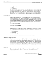
...crash data, enter the more crashinfo:data Current time: 04/21/2000 19:58:10 Last crash: 04/21/2000 03:58:56 !--- Output suppressed. Also, if only one supervisor engine is present and is in slot n+1 , ports n+1/1 and N+1/2 are still unable to eliminate the common causes. ...on its own, verify that the UPS does not have any problems. The switch might have two uplinks operational at the time that you are functional. Switch# more slavecrashinfo:data command. Contact Cisco Technical Support with Cisco Technical Support. Use the log of network connectivity or packet loss, perform ...
...crash data, enter the more crashinfo:data Current time: 04/21/2000 19:58:10 Last crash: 04/21/2000 03:58:56 !--- Output suppressed. Also, if only one supervisor engine is present and is in slot n+1 , ports n+1/1 and N+1/2 are still unable to eliminate the common causes. ...on its own, verify that the UPS does not have any problems. The switch might have two uplinks operational at the time that you are functional. Switch# more slavecrashinfo:data command. Contact Cisco Technical Support with Cisco Technical Support. Use the log of network connectivity or packet loss, perform ...


