
Installation Guide
Page 5
...-Warning Definition xii Obtaining Documentation and Submitting a Service Request xxi Product Overview 1-1 Catalyst 4900 Series Switch Applications 1-2 Catalyst 4948 Switch Software Features 1-3 Catalyst 4948-10GE and Catalyst 4928-10GE Switch Software Features 1-4 Hardware System Features 1-6 Switch Components 1-7 Traffic Ports on the Catalyst 4948 1-7 Traffic Ports on the Catalyst 4948-10GE 1-7 Traffic Ports on the Catalyst 4928-10GE 1-7 Console Port 1-7 Front Panel LEDs 1-9 Chassis Cooling 1-11 Power Supplies 1-12 Environmental...
...-Warning Definition xii Obtaining Documentation and Submitting a Service Request xxi Product Overview 1-1 Catalyst 4900 Series Switch Applications 1-2 Catalyst 4948 Switch Software Features 1-3 Catalyst 4948-10GE and Catalyst 4928-10GE Switch Software Features 1-4 Hardware System Features 1-6 Switch Components 1-7 Traffic Ports on the Catalyst 4948 1-7 Traffic Ports on the Catalyst 4948-10GE 1-7 Traffic Ports on the Catalyst 4928-10GE 1-7 Console Port 1-7 Front Panel LEDs 1-9 Chassis Cooling 1-11 Power Supplies 1-12 Environmental...

Installation Guide
Page 23
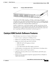
This chapter contains these sections: • Catalyst 4900 Series Switch Applications, page 1-2 • Catalyst 4948 Switch Software Features, page 1-3 • Catalyst 4948-10GE and Catalyst 4928-10GE Switch Software Features, page 1-4 • Hardware System Features, page 1-6 • Hardware System Features, page 1-6 • Switch Components, page 1-7 78-18039-02 Catalyst 4900 Series Switch Installation Guide 1-1 1 C H A P T E R Product Overview This chapter describes the Catalyst 4900 series switches, as well as system features and components.
This chapter contains these sections: • Catalyst 4900 Series Switch Applications, page 1-2 • Catalyst 4948 Switch Software Features, page 1-3 • Catalyst 4948-10GE and Catalyst 4928-10GE Switch Software Features, page 1-4 • Hardware System Features, page 1-6 • Hardware System Features, page 1-6 • Switch Components, page 1-7 78-18039-02 Catalyst 4900 Series Switch Installation Guide 1-1 1 C H A P T E R Product Overview This chapter describes the Catalyst 4900 series switches, as well as system features and components.

Installation Guide
Page 24
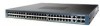
... Catalyst WS-C4948 10GE X2-1 X2-2 CON 48 MGT The Catalyst 4948-10GE switch has a 136-Gbps, nonblocking, full-duplex switching fabric, providing 102 million packets-per -second of switching capacity for high-speed applications. Catalyst 4900 Series Switch Installation Guide 1-2 78-18039-02 Figure 1-1 Catalyst 4948 Switch 113139 PS1 PS2 FAN STATUS 1 16 17 32 33 Catalyst 4948 CON 48 MGT 45 46 47 48 The Catalyst 4948 switch...
... Catalyst WS-C4948 10GE X2-1 X2-2 CON 48 MGT The Catalyst 4948-10GE switch has a 136-Gbps, nonblocking, full-duplex switching fabric, providing 102 million packets-per -second of switching capacity for high-speed applications. Catalyst 4900 Series Switch Installation Guide 1-2 78-18039-02 Figure 1-1 Catalyst 4948 Switch 113139 PS1 PS2 FAN STATUS 1 16 17 32 33 Catalyst 4948 CON 48 MGT 45 46 47 48 The Catalyst 4948 switch...
Installation Guide
Page 25
... Aggregation Protocol (PAgP) for 2,048 VLANs and 4,096 VLAN IDs - Cisco Inter Switch Link (ISL) tagging on all ports - Catalyst 4948 Switch Software Features The following is an overview of switching capacity for EFM - Q-in-Q for high-speed applications. Chapter 1 Product Overview Catalyst 4948 Switch Software Features Figure 1-3 Catalyst 4928-10GE Switch 271710 PS1 PS2 FAN STATUS 1 8 9 16 17 CON MGMT 24...
... Aggregation Protocol (PAgP) for 2,048 VLANs and 4,096 VLAN IDs - Cisco Inter Switch Link (ISL) tagging on all ports - Catalyst 4948 Switch Software Features The following is an overview of switching capacity for EFM - Q-in-Q for high-speed applications. Chapter 1 Product Overview Catalyst 4948 Switch Software Features Figure 1-3 Catalyst 4928-10GE Switch 271710 PS1 PS2 FAN STATUS 1 8 9 16 17 CON MGMT 24...
Installation Guide
Page 26
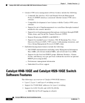
... groups (Ethernet Statistics, Alarms, Events, and History) on all relevant Cisco MIBs - Full SNMP instrumentation including entity-Management Information Base (MIB), all relevant standard MIBs, and all ports Catalyst 4900 Series Switch Installation Guide 1-4 78-18039-02 Catalyst 4948-10GE and Catalyst 4928-10GE Switch Software Features Chapter 1 Product Overview • Catalyst 4500 series management software features include the following: -
... groups (Ethernet Statistics, Alarms, Events, and History) on all relevant Cisco MIBs - Full SNMP instrumentation including entity-Management Information Base (MIB), all relevant standard MIBs, and all ports Catalyst 4900 Series Switch Installation Guide 1-4 78-18039-02 Catalyst 4948-10GE and Catalyst 4928-10GE Switch Software Features Chapter 1 Product Overview • Catalyst 4500 series management software features include the following: -

Installation Guide
Page 27
... new features with pruning extensions, and Cisco Group Management Protocol (CGMP) client • Embedded management features include the following : - Q-in -band management through any switch port through a terminal attached to the console interface - Chapter 1 Product Overview Catalyst 4948-10GE and Catalyst 4928-10GE Switch Software Features - Support for Gigabit EtherChannel • Catalyst 4500 series management software features include the...
... new features with pruning extensions, and Cisco Group Management Protocol (CGMP) client • Embedded management features include the following : - Q-in -band management through any switch port through a terminal attached to the console interface - Chapter 1 Product Overview Catalyst 4948-10GE and Catalyst 4928-10GE Switch Software Features - Support for Gigabit EtherChannel • Catalyst 4500 series management software features include the...
Installation Guide
Page 28
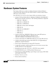
...8226; EtherChannel at 10/100/1000 Mbps (and 10 Gbps for the Catalyst 4948-10GE and Catalyst 4928-10GE) • Hardware-based access lists • Storm control in hardware Catalyst 4900 Series Switch Installation Guide 1-6 78-18039-02 IEEE 802.3u 100BASE-TX - IEEE... Overview Hardware System Features The Catalyst 4900 series switches are supported: - The following standards are high-performance dedicated Ethernet switches that fully integrate into the Catalyst family of the Catalyst 4900 series hardware features: • (Catalyst 4948 and 4948-10GE) 48 10BASE-T/100BASE-TX/1000BASE...
...8226; EtherChannel at 10/100/1000 Mbps (and 10 Gbps for the Catalyst 4948-10GE and Catalyst 4928-10GE) • Hardware-based access lists • Storm control in hardware Catalyst 4900 Series Switch Installation Guide 1-6 78-18039-02 IEEE 802.3u 100BASE-TX - IEEE... Overview Hardware System Features The Catalyst 4900 series switches are supported: - The following standards are high-performance dedicated Ethernet switches that fully integrate into the Catalyst family of the Catalyst 4900 series hardware features: • (Catalyst 4948 and 4948-10GE) 48 10BASE-T/100BASE-TX/1000BASE...
Installation Guide
Page 29
... console and management ports. The Management port on the Catalyst 4948-10GE There are 28 1000BASE-X Ethernet ports using inband access (Telnet, SNMP, etc.). Figure 1-4 and Figure 1-5 show the location of the management and console ports on the Management port; Chapter 1 Product Overview Switch Components Switch Components This section describes the hardware components. The interface...
... console and management ports. The Management port on the Catalyst 4948-10GE There are 28 1000BASE-X Ethernet ports using inband access (Telnet, SNMP, etc.). Figure 1-4 and Figure 1-5 show the location of the management and console ports on the Management port; Chapter 1 Product Overview Switch Components Switch Components This section describes the hardware components. The interface...
Installation Guide
Page 34
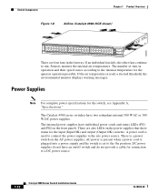
... the internal air temperatures. If the air temperature exceeds a desired threshold, the environmental monitor displays warning messages. The Catalyst 4900 series switches have individual power cords and status LEDs (PS1 and PS2 on the power supplies that show status for the...power cord is plugged into a power supply and the switch is used to connect the power supplies to the On position. 130085 Switch Components Chapter 1 Product Overview Figure 1-8 Airflow (Catalyst 4948-10GE shown) PS1 PS2 FAN STATUS 1 16 17 32 33 Catalyst WS-C4948 10GE X2-1 X2-2 CON 48 MGT There are also ...
... the internal air temperatures. If the air temperature exceeds a desired threshold, the environmental monitor displays warning messages. The Catalyst 4900 series switches have individual power cords and status LEDs (PS1 and PS2 on the power supplies that show status for the...power cord is plugged into a power supply and the switch is used to connect the power supplies to the On position. 130085 Switch Components Chapter 1 Product Overview Figure 1-8 Airflow (Catalyst 4948-10GE shown) PS1 PS2 FAN STATUS 1 16 17 32 33 Catalyst WS-C4948 10GE X2-1 X2-2 CON 48 MGT There are also ...
Installation Guide
Page 43
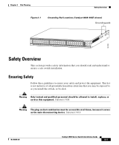
Statement 1019 78-18039-02 Catalyst 4900 Series Switch Installation Guide 2-7 This list is not inclusive of all times, because it serves as you install the switch, so be alert. Statement 1030 Warning The plug-socket combination must be accessible at all ...equipment. Ensuring Safety Follow these guidelines to ensure a safe switch installation. Chapter 2 Site Planning Safety Overview Figure 2-1 Grounding Pad Locations (Catalyst 4849-10GE shown) Grounding pads 130180 PS1 PS2 FAN STATUS 1 16 17 32 33 Catalyst WS-C4948 10GE X2-1 X2-2 CON 48 MGT Safety Overview This section...
Statement 1019 78-18039-02 Catalyst 4900 Series Switch Installation Guide 2-7 This list is not inclusive of all times, because it serves as you install the switch, so be alert. Statement 1030 Warning The plug-socket combination must be accessible at all ...equipment. Ensuring Safety Follow these guidelines to ensure a safe switch installation. Chapter 2 Site Planning Safety Overview Figure 2-1 Grounding Pad Locations (Catalyst 4849-10GE shown) Grounding pads 130180 PS1 PS2 FAN STATUS 1 16 17 32 33 Catalyst WS-C4948 10GE X2-1 X2-2 CON 48 MGT Safety Overview This section...
Installation Guide
Page 52
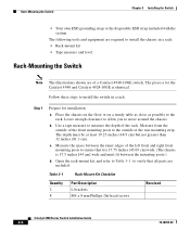
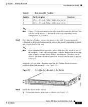
Step 1 Prepare for the Catalyst 4948 and Catalyst 4928-10GE is 17.5 inches [44 cm] wide and must be at least 19.25 inches (48.9 cm) but...on a sturdy table as close as possible to measure the depth of a Catalyst 4948-10GE switch. Measure the space between the mounting posts.) d. Leave enough clearance to allow you to install the switch in a rack: • Rack-mount kit • Tape measure and level... 3-1 Rack-Mount Kit Checklist Quantity 2 8 Part Description L brackets M4 x 8 mm Phillips flat-head screws Received Catalyst 4900 Series Switch Installation Guide 3-6 78-18039-02
Step 1 Prepare for the Catalyst 4948 and Catalyst 4928-10GE is 17.5 inches [44 cm] wide and must be at least 19.25 inches (48.9 cm) but...on a sturdy table as close as possible to measure the depth of a Catalyst 4948-10GE switch. Measure the space between the mounting posts.) d. Leave enough clearance to allow you to install the switch in a rack: • Rack-mount kit • Tape measure and level... 3-1 Rack-Mount Kit Checklist Quantity 2 8 Part Description L brackets M4 x 8 mm Phillips flat-head screws Received Catalyst 4900 Series Switch Installation Guide 3-6 78-18039-02
Installation Guide
Page 53
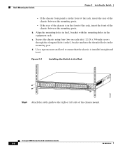
...the L brackets connect the chassis to the Switch 130086 PS1 PS2 FAN STATUS 1 16 17 32 33 Catalyst WS-C4948 10GE X2-1 X2-2 CON 48 MGT Step 3 Install the chassis in the rack as follows (see Figure 3-3): 78-18039-02 Catalyst 4900 Series Switch Installation Guide 3-7 Position the chassis in the ...on the chassis, determine whether to install the chassis from the front or the rear of the rack. Chapter 3 Installing the Switch Rack-Mounting the Switch Table 3-1 Quantity 4 4 Rack-Mount Kit Checklist Part Description Received 12-24 x 3/4-inch Phillips binder-head screws 10-32 ...
...the L brackets connect the chassis to the Switch 130086 PS1 PS2 FAN STATUS 1 16 17 32 33 Catalyst WS-C4948 10GE X2-1 X2-2 CON 48 MGT Step 3 Install the chassis in the rack as follows (see Figure 3-3): 78-18039-02 Catalyst 4900 Series Switch Installation Guide 3-7 Position the chassis in the ...on the chassis, determine whether to install the chassis from the front or the rear of the rack. Chapter 3 Installing the Switch Rack-Mounting the Switch Table 3-1 Quantity 4 4 Rack-Mount Kit Checklist Part Description Received 12-24 x 3/4-inch Phillips binder-head screws 10-32 ...
Installation Guide
Page 54
b. c. d. Rack-Mounting the Switch Chapter 3 Installing the Switch - If the chassis front panel is in the front of the rack, insert the rear of the chassis mount. Secure the chassis using four (two ..., insert the front of the chassis between the mounting posts. - Catalyst 4900 Series Switch Installation Guide 3-8 78-18039-02 Use a tape measure and level to ensure that the chassis is in the Rack 130087 PS1 PS2 FAN STATUS 1 16 17 32 33 Catalyst WS-C4948 10GE X2-1 X2-2 CON 48 MGT Step 4 Attach the cable guide...
b. c. d. Rack-Mounting the Switch Chapter 3 Installing the Switch - If the chassis front panel is in the front of the rack, insert the rear of the chassis mount. Secure the chassis using four (two ..., insert the front of the chassis between the mounting posts. - Catalyst 4900 Series Switch Installation Guide 3-8 78-18039-02 Use a tape measure and level to ensure that the chassis is in the Rack 130087 PS1 PS2 FAN STATUS 1 16 17 32 33 Catalyst WS-C4948 10GE X2-1 X2-2 CON 48 MGT Step 4 Attach the cable guide...
Installation Guide
Page 55
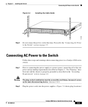
... The plug-socket combination must be accessible at this time. Chapter 3 Installing the Switch Connecting AC Power to the Switch Figure 3-4 Installing the Cable Guide 130089 PS1 PS2 FAN STATUS 1 16 17 32 33 Catalyst WS-C4948 10GE X2-1 X2-2 CON 48 MGT Step 5 Do not connect the power cord at... all of the site power and grounding requirements described in the "Grounding Requirements" section on page 3-9. Proceed to the "Connecting AC Power to the Switch" section on page 2-6.
... The plug-socket combination must be accessible at this time. Chapter 3 Installing the Switch Connecting AC Power to the Switch Figure 3-4 Installing the Cable Guide 130089 PS1 PS2 FAN STATUS 1 16 17 32 33 Catalyst WS-C4948 10GE X2-1 X2-2 CON 48 MGT Step 5 Do not connect the power cord at... all of the site power and grounding requirements described in the "Grounding Requirements" section on page 3-9. Proceed to the "Connecting AC Power to the Switch" section on page 2-6.
Installation Guide
Page 63
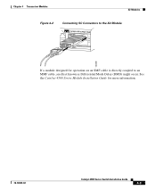
Chapter 4 Transceiver Modules X2 Modules Figure 4-2 Connecting SC Connectors to the X2 Module Catalyst WS-C4948 10GE X2-1 X2-2 CON MGT 130088 If a module designed for more information. 78-18039-02 Catalyst 4900 Series Switch Installation Guide 4-3 See the Catalyst 4500 Series Module Installation Guide for operation on an SMF cable is directly coupled to an MMF cable, an effect known as Differential Mode Delay (DMD) might occur.
Chapter 4 Transceiver Modules X2 Modules Figure 4-2 Connecting SC Connectors to the X2 Module Catalyst WS-C4948 10GE X2-1 X2-2 CON MGT 130088 If a module designed for more information. 78-18039-02 Catalyst 4900 Series Switch Installation Guide 4-3 See the Catalyst 4500 Series Module Installation Guide for operation on an SMF cable is directly coupled to an MMF cable, an effect known as Differential Mode Delay (DMD) might occur.

Installation Guide
Page 64
Catalyst 4900 Series Switch Installation Guide 4-4 78-18039-02 X2 Modules Chapter 4 Transceiver Modules Figure 4-3 Installing the 10-Gigabit Ethernet X2 Module Catalyst WS-C4948 10GE CON X1 MGT LINK X2 Catalyst WS-C4948 10GE CON X1 MGT X2 130091 Caution If you attempt to insert the bottom X2 module with the cooling fins pointing up, you will probably permanently damage the connector. For either the top or bottom connector, forcing a module could potentially damage both the module and the switch.
Catalyst 4900 Series Switch Installation Guide 4-4 78-18039-02 X2 Modules Chapter 4 Transceiver Modules Figure 4-3 Installing the 10-Gigabit Ethernet X2 Module Catalyst WS-C4948 10GE CON X1 MGT LINK X2 Catalyst WS-C4948 10GE CON X1 MGT X2 130091 Caution If you attempt to insert the bottom X2 module with the cooling fins pointing up, you will probably permanently damage the connector. For either the top or bottom connector, forcing a module could potentially damage both the module and the switch.

Installation Guide
Page 76
... pair 1 Bidirectional data pair 3 Bidirectional data pair 3 Catalyst 4900 Series Switch Installation Guide A-2 78-18039-02 Table A-2 lists the 10/100BASE-T port pinouts. Table A-3 lists the 10/100/1000BASE-T port pinouts. Management Port Appendix A Specifications Management Port The 10/100BASE-T (Catalyst 4948) or 10/100/1000BASE-T (Catalyst 4948-10GE) management port use an RJ-45 receptacle with...
... pair 1 Bidirectional data pair 3 Bidirectional data pair 3 Catalyst 4900 Series Switch Installation Guide A-2 78-18039-02 Table A-2 lists the 10/100BASE-T port pinouts. Table A-3 lists the 10/100/1000BASE-T port pinouts. Management Port Appendix A Specifications Management Port The 10/100BASE-T (Catalyst 4948) or 10/100/1000BASE-T (Catalyst 4948-10GE) management port use an RJ-45 receptacle with...
Installation Guide
Page 77
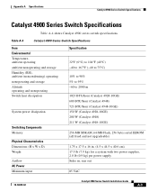
... Switching Components Memory Physical Characteristics Dimensions (H x W x D) Weight Airflow AC Power Minimum input Specification 32°F (0°C) to 104°F (40°C) -40 to 167°F (-40 to 75°C) 10% to 90% 5% to 95% -60 to 2000 m 1023 BTU/hour (Catalyst 4928-10GE) 600 BTU/hour (Catalyst 4948) 723 BTU/hour (Catalyst 4948-10GE) 150 W (Catalyst 4928-10GE) 200 W (Catalyst 4948) 211 W (Catalyst 4948-10GE...
... Switching Components Memory Physical Characteristics Dimensions (H x W x D) Weight Airflow AC Power Minimum input Specification 32°F (0°C) to 104°F (40°C) -40 to 167°F (-40 to 75°C) 10% to 90% 5% to 95% -60 to 2000 m 1023 BTU/hour (Catalyst 4928-10GE) 600 BTU/hour (Catalyst 4948) 723 BTU/hour (Catalyst 4948-10GE) 150 W (Catalyst 4928-10GE) 200 W (Catalyst 4948) 211 W (Catalyst 4948-10GE...

Installation Guide
Page 125
... compliance with national and international standards as described in compliance with the 1999/5/EC directive, which includes the safety and EMC standards listed. The Catalyst 4948, Catalyst 4948-10GE, and Catalyst 4928-10GE switches are in Table C-1. Appendix C Compliance Information and Translated Safety Warnings Regulatory Standards Compliance Regulatory Standards Compliance This section includes all regulatory, safety, EMC (Class...
... compliance with national and international standards as described in compliance with the 1999/5/EC directive, which includes the safety and EMC standards listed. The Catalyst 4948, Catalyst 4948-10GE, and Catalyst 4928-10GE switches are in Table C-1. Appendix C Compliance Information and Translated Safety Warnings Regulatory Standards Compliance Regulatory Standards Compliance This section includes all regulatory, safety, EMC (Class...

Installation Guide
Page 132
... FCC Modifying the equipment without Cisco's authorization may be necessary. In that event, your own expense. EMC Class A Notices and Warnings Appendix C Compliance Information and Translated Safety Warnings Suomalainen: Catalyst 4948 and Catalyst 4948-10GE switches Tämä laite on ... ja määräysten mukainen. For more information about perchlorate and best management practices for the Catalyst 4948 and Catalyst 4948-10GE switches. EMC Class A Notices and Warnings This section includes the EMC Class A warnings for perchlorate-containing substances...
... FCC Modifying the equipment without Cisco's authorization may be necessary. In that event, your own expense. EMC Class A Notices and Warnings Appendix C Compliance Information and Translated Safety Warnings Suomalainen: Catalyst 4948 and Catalyst 4948-10GE switches Tämä laite on ... ja määräysten mukainen. For more information about perchlorate and best management practices for the Catalyst 4948 and Catalyst 4948-10GE switches. EMC Class A Notices and Warnings This section includes the EMC Class A warnings for perchlorate-containing substances...
