
Data Sheet
Page 5
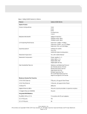
... MSFC: up to 210 Mpps Supervisor 720: up to 400 Mpps Catalyst OS (CatOS) Cisco IOS CatOS/IOS Hybrid Configuration Yes, with stateful failover Power supplies (1+1) Switch fabric (1+1) Replaceable clock Replaceable fan tray Gateway Load Balancing Protocol Hot Standby Router Protocol Multimodule EtherChannel Rapid Spanning Tree Multiple Spanning Tree... support Inline Power 288 ports 194 ports (2 ports provided on supervisor engine) 32 ports 12 modules with 24 port adapters 192 48 Cisco Systems, Inc. Important Notices and Privacy Statement. All contents are Copyright © 1992-2004...
... MSFC: up to 210 Mpps Supervisor 720: up to 400 Mpps Catalyst OS (CatOS) Cisco IOS CatOS/IOS Hybrid Configuration Yes, with stateful failover Power supplies (1+1) Switch fabric (1+1) Replaceable clock Replaceable fan tray Gateway Load Balancing Protocol Hot Standby Router Protocol Multimodule EtherChannel Rapid Spanning Tree Multiple Spanning Tree... support Inline Power 288 ports 194 ports (2 ports provided on supervisor engine) 32 ports 12 modules with 24 port adapters 192 48 Cisco Systems, Inc. Important Notices and Privacy Statement. All contents are Copyright © 1992-2004...
Data Sheet
Page 18
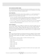
... to the WAN edge • 6- Only one supply is installed, it operates in selecting the chassis, power supplies, power cables, and fan trays that will meet your requirements. Chassis Applications The Cisco Catalyst 6500 Series provides a selection of chassis, including 3-, 6-, 9-, and 13-slot models with slots arranged horizontally and a 9-slot model with slots...
... to the WAN edge • 6- Only one supply is installed, it operates in selecting the chassis, power supplies, power cables, and fan trays that will meet your requirements. Chassis Applications The Cisco Catalyst 6500 Series provides a selection of chassis, including 3-, 6-, 9-, and 13-slot models with slots arranged horizontally and a 9-slot model with slots...
Data Sheet
Page 19
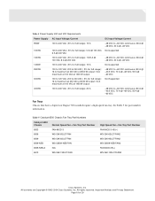
... 5 Catalyst 6500 Chassis Fan Tray Part Numbers Catalyst 6500 Chassis Normal Speed Fan-Fan Tray Part Number 6503 FAN-MOD-3 6506 WS-C6K-6SLOT-FAN 6509 WS-C6K-6SLOT-FAN 6509-NEB WS-C6509-NEB-FAN 6509-NEB-A N/A 6513 WS-C6K-13SLOT-FAN High Speed Fan-Fan Tray Part Number FAN-MOD-3-HS(=) WS-C6K-6SLOT-FAN2 WS-C6K-9SLOT-FAN2 WS-C6509-NEB-FAN2 FAN-MOD-09(=) WS-C6K-13SLOT-FAN2 Cisco Systems, Inc. See...
... 5 Catalyst 6500 Chassis Fan Tray Part Numbers Catalyst 6500 Chassis Normal Speed Fan-Fan Tray Part Number 6503 FAN-MOD-3 6506 WS-C6K-6SLOT-FAN 6509 WS-C6K-6SLOT-FAN 6509-NEB WS-C6509-NEB-FAN 6509-NEB-A N/A 6513 WS-C6K-13SLOT-FAN High Speed Fan-Fan Tray Part Number FAN-MOD-3-HS(=) WS-C6K-6SLOT-FAN2 WS-C6K-9SLOT-FAN2 WS-C6509-NEB-FAN2 FAN-MOD-09(=) WS-C6K-13SLOT-FAN2 Cisco Systems, Inc. See...
User Guide
Page 18
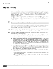
... a module must have a slot cover installed in either Figure 7 (Catalyst 6509 switch), Figure 8 (Cisco 7606 router), or Figure 9 (Cisco 7609 router). Nine module slots are provided on the right side of the chassis. Any attempt to remove the fan tray will damage the tamper seal, which indicates tampering has occurred. six module slots are...
... a module must have a slot cover installed in either Figure 7 (Catalyst 6509 switch), Figure 8 (Cisco 7606 router), or Figure 9 (Cisco 7609 router). Nine module slots are provided on the right side of the chassis. Any attempt to remove the fan tray will damage the tamper seal, which indicates tampering has occurred. six module slots are...
Upgrade Guide
Page 1
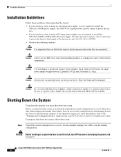
...-If your switch or router is rated 10 A @ -40 to power the fan tray. Caution It is using a DC-input power supply, you are required to power the fan tray. You must provide a separate, direct connection to install the WS-CDC-2500W or PWR-4000-DC power supply. All rights reserved. Each input of... power output to -60 VDC. Note AC-Input Systems-If your switch or router is important that you are presented. Catalyst 6509-NEB Switch and Cisco OSR-7609 Router Upgrade Note Product Number: WS-6509-NEB-UPGRD= This publication describes how to upgrade your Catalyst 6509-NEB switch or...
...-If your switch or router is rated 10 A @ -40 to power the fan tray. Caution It is using a DC-input power supply, you are required to power the fan tray. You must provide a separate, direct connection to install the WS-CDC-2500W or PWR-4000-DC power supply. All rights reserved. Each input of... power output to -60 VDC. Note AC-Input Systems-If your switch or router is important that you are presented. Catalyst 6509-NEB Switch and Cisco OSR-7609 Router Upgrade Note Product Number: WS-6509-NEB-UPGRD= This publication describes how to upgrade your Catalyst 6509-NEB switch or...
Upgrade Guide
Page 2
... Guidelines, page 4 • Shutting Down the System, page 4 • Replacing the Panel Safety Cover, page 5 • Replacing the Fan Tray, page 7 • Replacing the Power Supply, page 10 • Connecting Power to the Fan Tray, page 13 • Replacing the Supervisor Engine, page 17 • Powering Up the System, page 21 • Verifying Installation... circuitry and be removed to locate its translation in procedures that power is removed from the DC circuit. Statement 1028 Catalyst 6509-NEB Switch and Cisco OSR-7609 Router Upgrade Note 2 78-16162-02
... Guidelines, page 4 • Shutting Down the System, page 4 • Replacing the Panel Safety Cover, page 5 • Replacing the Fan Tray, page 7 • Replacing the Power Supply, page 10 • Connecting Power to the Fan Tray, page 13 • Replacing the Supervisor Engine, page 17 • Powering Up the System, page 21 • Verifying Installation... circuitry and be removed to locate its translation in procedures that power is removed from the DC circuit. Statement 1028 Catalyst 6509-NEB Switch and Cisco OSR-7609 Router Upgrade Note 2 78-16162-02
Upgrade Guide
Page 3
... system is operating. Statement 1046 Parts List The following items are included in accordance with national and local wiring regulations. The fan tray ships with redundant power supplies. Statement 1034 Warning This product requires short-circuit (overcurrent) protection, to be allowed to install... Catalyst 6509-NEB Switch and Cisco OSR-7609 Router Upgrade Note 3 Install only in the upgrade kit: • One high speed fan tray The high speed fan tray provides additional cooling for AC-input systems) The fan tray power cable provides a connection between the fan tray and the 3000 W AC-...
... system is operating. Statement 1046 Parts List The following items are included in accordance with national and local wiring regulations. The fan tray ships with redundant power supplies. Statement 1034 Warning This product requires short-circuit (overcurrent) protection, to be allowed to install... Catalyst 6509-NEB Switch and Cisco OSR-7609 Router Upgrade Note 3 Install only in the upgrade kit: • One high speed fan tray The high speed fan tray provides additional cooling for AC-input systems) The fan tray power cable provides a connection between the fan tray and the 3000 W AC-...
Upgrade Guide
Page 4
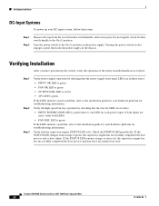
...6509-NEB Switch and Cisco OSR-7609 Router Upgrade Note 4 78-16162-02 Caution Do not exert too much pressure on /off switch, turn OFF the power and unplug the power cord. For more information, refer to install and remove power supplies. Each input of the fan tray is rated 10 A ... supply, you should first upload the current configuration to a server. Before you shut down the system, you are required to install the WS-CDC-2500W or PWR-4000-DC power supply. Installation Guidelines Installation Guidelines Follow these steps: Step 1 Upload the current configuration to the nonvolatile...
...6509-NEB Switch and Cisco OSR-7609 Router Upgrade Note 4 78-16162-02 Caution Do not exert too much pressure on /off switch, turn OFF the power and unplug the power cord. For more information, refer to install and remove power supplies. Each input of the fan tray is rated 10 A ... supply, you should first upload the current configuration to a server. Before you shut down the system, you are required to install the WS-CDC-2500W or PWR-4000-DC power supply. Installation Guidelines Installation Guidelines Follow these steps: Step 1 Upload the current configuration to the nonvolatile...
Upgrade Guide
Page 6
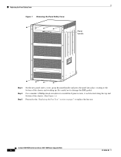
... the panel handle and press the panel into place, starting at the bottom of the chassis. (See Figure 2.) Proceed to the "Replacing the Fan Tray" section on page 7 to replace the fan tray. Catalyst 6509-NEB Switch and Cisco OSR-7609 Router Upgrade Note 6 78-16162-02 Be careful not to damage the EMI gasket.
... the panel handle and press the panel into place, starting at the bottom of the chassis. (See Figure 2.) Proceed to the "Replacing the Fan Tray" section on page 7 to replace the fan tray. Catalyst 6509-NEB Switch and Cisco OSR-7609 Router Upgrade Note 6 78-16162-02 Be careful not to damage the EMI gasket.
Upgrade Guide
Page 7
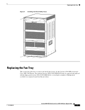
The standard fan tray (WS-C6509-NEB-FAN) must be removed and replaced with the high-speed fan tray (WS-C6509-NEB-FAN2). A flat-blade or number 2 Phillips-head screwdriver is required to remove and install the fan tray for the Catalyst 6509-NEB switch and Cisco OSR-7609 Router. Figure 2 Installing the Panel Safety Cover Replacing the Fan Tray 105071 Replacing the Fan Tray This section describes how to perform this procedure. 78-16162-02 Catalyst 6509-NEB Switch and Cisco OSR-7609 Router Upgrade Note 7
The standard fan tray (WS-C6509-NEB-FAN) must be removed and replaced with the high-speed fan tray (WS-C6509-NEB-FAN2). A flat-blade or number 2 Phillips-head screwdriver is required to remove and install the fan tray for the Catalyst 6509-NEB switch and Cisco OSR-7609 Router. Figure 2 Installing the Panel Safety Cover Replacing the Fan Tray 105071 Replacing the Fan Tray This section describes how to perform this procedure. 78-16162-02 Catalyst 6509-NEB Switch and Cisco OSR-7609 Router Upgrade Note 7
Upgrade Guide
Page 8
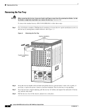
... fan tray clear of the fan tray with one hand and pull the fan tray outward about 1 inch; Once the fans have stopped spinning, pull the fan tray out further and support the underside of the chassis, and put it gently, if necessary, to unseat the power connector from the spinning fan blades. Statement 258 To remove the standard fan tray (WS-C6509-NEB-FAN...
... fan tray clear of the fan tray with one hand and pull the fan tray outward about 1 inch; Once the fans have stopped spinning, pull the fan tray out further and support the underside of the chassis, and put it gently, if necessary, to unseat the power connector from the spinning fan blades. Statement 258 To remove the standard fan tray (WS-C6509-NEB-FAN...
Upgrade Guide
Page 9
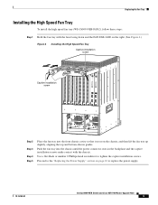
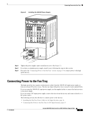
...Replacing the Fan Tray Installing the High Speed Fan Tray To install the high speed fan tray (WS-C6509-NEB-FAN2), follow these steps: Step 1 Hold the fan tray with the chassis. Use a flat-blade or number 2 Phillips-head screwdriver to the "Replacing the Power Supply" section on the chassis, and then lift the fan tray up slightly... OK FAIL INPUT OK FAN OUTPUT OK FAIL Step 2 Step 3 Step 4 Step 5 Place the fan tray into the front chassis cavity so that it rests on page 10 to replace the power supply. 78-16162-02 Catalyst 6509-NEB Switch and Cisco OSR-7609 Router Upgrade Note 9 Proceed...
...Replacing the Fan Tray Installing the High Speed Fan Tray To install the high speed fan tray (WS-C6509-NEB-FAN2), follow these steps: Step 1 Hold the fan tray with the chassis. Use a flat-blade or number 2 Phillips-head screwdriver to the "Replacing the Power Supply" section on the chassis, and then lift the fan tray up slightly... OK FAIL INPUT OK FAN OUTPUT OK FAIL Step 2 Step 3 Step 4 Step 5 Place the fan tray into the front chassis cavity so that it rests on page 10 to replace the power supply. 78-16162-02 Catalyst 6509-NEB Switch and Cisco OSR-7609 Router Upgrade Note 9 Proceed...
Upgrade Guide
Page 10
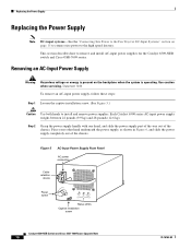
...AC-input power supply, follow these steps: Step 1 Loosen the captive installation screw. (See Figure 5.) Caution Use both hands to the high speed fan tray. Place your other hand underneath the power supply, as shown in Figure 6, and slide the power supply completely out of the chassis. Each Catalyst ...servicing. Replacing the Power Supply Replacing the Power Supply Note DC-input systems-See the "Connecting Site Power to the Fan Tray for the Catalyst 6509-NEB switch and Cisco OSR-7609 router. Removing an AC-Input Power Supply Warning Hazardous voltage or energy is present on page 15 to ...
...AC-input power supply, follow these steps: Step 1 Loosen the captive installation screw. (See Figure 5.) Caution Use both hands to the high speed fan tray. Place your other hand underneath the power supply, as shown in Figure 6, and slide the power supply completely out of the chassis. Each Catalyst ...servicing. Replacing the Power Supply Replacing the Power Supply Note DC-input systems-See the "Connecting Site Power to the Fan Tray for the Catalyst 6509-NEB switch and Cisco OSR-7609 router. Removing an AC-Input Power Supply Warning Hazardous voltage or energy is present on page 15 to ...
Upgrade Guide
Page 13
...-16162-02 Catalyst 6509-NEB Switch and Cisco OSR-7609 Router Upgrade Note 13 The following the steps in this section. Connecting Power to the Fan Tray The high-speed fan tray requires external power, either from the 3000 W AC-input power supply or from the fan tray and connect directly to a DC power source... OC3 POS MM 2 STATUS OSM-8OC3-POS MM 1 1 2 LINK 1 STATUS OC12 POS MM OSM-40C12-POS-MM SWITCH FABRIC MDL HIGH SPEED FAN STATUS OC12 POS MM WS-C6500-SFM SWITCH FABRIC MDL WS-C6500-SFM STATUS ACTIVE STATUS ACTIVE OC12 POS MM OSM-40C12-POS-MM 2 STATUS 1 OSM-40C12-POS-MM...
...-16162-02 Catalyst 6509-NEB Switch and Cisco OSR-7609 Router Upgrade Note 13 The following the steps in this section. Connecting Power to the Fan Tray The high-speed fan tray requires external power, either from the 3000 W AC-input power supply or from the fan tray and connect directly to a DC power source... OC3 POS MM 2 STATUS OSM-8OC3-POS MM 1 1 2 LINK 1 STATUS OC12 POS MM OSM-40C12-POS-MM SWITCH FABRIC MDL HIGH SPEED FAN STATUS OC12 POS MM WS-C6500-SFM SWITCH FABRIC MDL WS-C6500-SFM STATUS ACTIVE STATUS ACTIVE OC12 POS MM OSM-40C12-POS-MM 2 STATUS 1 OSM-40C12-POS-MM...
Upgrade Guide
Page 14
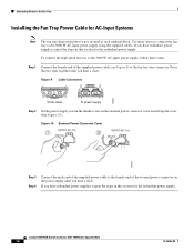
Connecting Power to the fan tray wire connector. Catalyst 6509-NEB Switch and Cisco OSR-7609 Router Upgrade Note 14 78-16162-02 Press the two ends together until you have redundant power supplies, repeat the steps in this section for AC-Input Systems Note The fan tray ships with power wires secured at each terminal...
Connecting Power to the fan tray wire connector. Catalyst 6509-NEB Switch and Cisco OSR-7609 Router Upgrade Note 14 78-16162-02 Press the two ends together until you have redundant power supplies, repeat the steps in this section for AC-Input Systems Note The fan tray ships with power wires secured at each terminal...
Upgrade Guide
Page 15
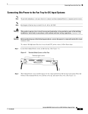
... follow these steps: Step 1 Locate the terminal block covers on the fan tray. (See Figure 11.) Figure 11 Terminal Block Covers on Fan Tray Terminal block covers 48V INPUT 1 INPUT POWER GOOD RTN -48VDC GND WS-C6500-NEB-FAN2 HIGH SPEED FAN 48V INPUT 2 FAN FAIL INPUT POWER GOOD RTN -48VDC GND 105081 Step 2 The terminal ... of the terminal block cover, lift the cover up, and remove the cover. (See Figure 12.) 78-16162-02 Catalyst 6509-NEB Switch and Cisco OSR-7609 Router Upgrade Note 15 Press the bottom of the fan tray is held in accordance with national and local wiring regulations.
... follow these steps: Step 1 Locate the terminal block covers on the fan tray. (See Figure 11.) Figure 11 Terminal Block Covers on Fan Tray Terminal block covers 48V INPUT 1 INPUT POWER GOOD RTN -48VDC GND WS-C6500-NEB-FAN2 HIGH SPEED FAN 48V INPUT 2 FAN FAIL INPUT POWER GOOD RTN -48VDC GND 105081 Step 2 The terminal ... of the terminal block cover, lift the cover up, and remove the cover. (See Figure 12.) 78-16162-02 Catalyst 6509-NEB Switch and Cisco OSR-7609 Router Upgrade Note 15 Press the bottom of the fan tray is held in accordance with national and local wiring regulations.
Upgrade Guide
Page 16
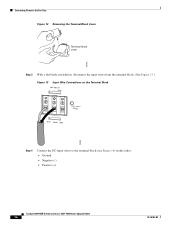
Connecting Power to the Fan Tray Figure 12 Removing the Terminal Block Cover Terminal block cover 105082 Step 3 With a flat blade screwdriver, disconnect the input wires from the terminal block. (See Figure 13.) Figure 13 Input Wire Connections on the Terminal Block 48V INPUT 1 + GND INPUT POWER GOOD RTN -48vdc GND 105084 Step 4 Connect the DC-input wires to the terminal block (see Figure 14) in this order: • Ground • Negative (-) • Positive (+) Catalyst 6509-NEB Switch and Cisco OSR-7609 Router Upgrade Note 16 78-16162-02
Connecting Power to the Fan Tray Figure 12 Removing the Terminal Block Cover Terminal block cover 105082 Step 3 With a flat blade screwdriver, disconnect the input wires from the terminal block. (See Figure 13.) Figure 13 Input Wire Connections on the Terminal Block 48V INPUT 1 + GND INPUT POWER GOOD RTN -48vdc GND 105084 Step 4 Connect the DC-input wires to the terminal block (see Figure 14) in this order: • Ground • Negative (-) • Positive (+) Catalyst 6509-NEB Switch and Cisco OSR-7609 Router Upgrade Note 16 78-16162-02
Upgrade Guide
Page 22
...high speed fan tray operation by checking that the fan tray LEDs are in the chassis. Check the STATUS LED periodically. Verify that locks the power supply in these: • INPUT POWER GOOD LED is green (there is one LED for troubleshooting information. Catalyst 6509-NEB Switch and Cisco OSR-7609 ...Router Upgrade Note 22 78-16162-02 Verifying Installation After you have encountered an error. if both inputs are used, verify both LEDs) • FAN FAIL LED is green If the LEDs indicate a problem, ...
...high speed fan tray operation by checking that the fan tray LEDs are in the chassis. Check the STATUS LED periodically. Verify that locks the power supply in these: • INPUT POWER GOOD LED is green (there is one LED for troubleshooting information. Catalyst 6509-NEB Switch and Cisco OSR-7609 ...Router Upgrade Note 22 78-16162-02 Verifying Installation After you have encountered an error. if both inputs are used, verify both LEDs) • FAN FAIL LED is green If the LEDs indicate a problem, ...

