Hardware Maintenance Manual
Page 3
...PROOF OF PAYMENT) TO THE PLACE OF PURCHASE FOR A FULL REFUND. Title to everyone are service marks, and Cisco, Cisco Systems, EtherSwitch, Kalpana, and the Cisco logo are trademarks, Access by the Government is error free or that Customer will be eligible for such tests. ...a license fee was exported under the multinational uplift program. Notice of Restricted Rights: Use, duplication, or disclosure by Cisco and Bringing the power of internetworking to Software and documentation shall remain solely with any necessary equipment for a remedy, Customer must report all...
...PROOF OF PAYMENT) TO THE PLACE OF PURCHASE FOR A FULL REFUND. Title to everyone are service marks, and Cisco, Cisco Systems, EtherSwitch, Kalpana, and the Cisco logo are trademarks, Access by the Government is error free or that Customer will be eligible for such tests. ...a license fee was exported under the multinational uplift program. Notice of Restricted Rights: Use, duplication, or disclosure by Cisco and Bringing the power of internetworking to Software and documentation shall remain solely with any necessary equipment for a remedy, Customer must report all...

Hardware Maintenance Manual
Page 6
... Solving 4-1 Troubleshooting the Power and Cooling Systems 4-2 Troubleshooting the Network Processor Modules and Cables 4-2 Environmental Reporting Features 4-3 Reading Front-Panel LED Indicators 4-3 System LED Operation 4-3 Reading Network Processor Module LED Indicators 4-4 Ethernet Network Processor Module LED Indicators 4-4 Token Ring Network Processor Module LED Indicators 4-5 Four Port Serial Module Indicators 4-6 Dual Serial Network Processor Module LED Indicators 4-7 FDDI...
... Solving 4-1 Troubleshooting the Power and Cooling Systems 4-2 Troubleshooting the Network Processor Modules and Cables 4-2 Environmental Reporting Features 4-3 Reading Front-Panel LED Indicators 4-3 System LED Operation 4-3 Reading Network Processor Module LED Indicators 4-4 Ethernet Network Processor Module LED Indicators 4-4 Token Ring Network Processor Module LED Indicators 4-5 Four Port Serial Module Indicators 4-6 Dual Serial Network Processor Module LED Indicators 4-7 FDDI...

Hardware Maintenance Manual
Page 10
... Dual-Attachment FDDI Connections 3-13 Cisco 4000 Series DC-Input Power Supply-Rear View 3-20 Cisco 4000 Series AC-Input Power Supply-Rear View 3-20 DC-Input Power Supply Connections 3-21 Cisco 4000 Series-Front Panel Indicators 4-3 Dual-Port Ethernet Network Processor Module LEDs 4-4 Single-Port Ethernet Network Processor Module LEDs 4-4 Token Ring Module Network Connector 4-5 Four-Port Serial...
... Dual-Attachment FDDI Connections 3-13 Cisco 4000 Series DC-Input Power Supply-Rear View 3-20 Cisco 4000 Series AC-Input Power Supply-Rear View 3-20 DC-Input Power Supply Connections 3-21 Cisco 4000 Series-Front Panel Indicators 4-3 Dual-Port Ethernet Network Processor Module LEDs 4-4 Single-Port Ethernet Network Processor Module LEDs 4-4 Token Ring Module Network Connector 4-5 Four-Port Serial...

Hardware Maintenance Manual
Page 15
... updated and shipped monthly, so it may be familiar with a DC-input power supply. Note To order UniverCD, Cisco's online library of product information, or printed publications, refer to date than printed documentation. Document Organization The major sections of the Cisco 4000 series features and physical specifications. • Chapter 2, "Preparing for Installation," includes...
... updated and shipped monthly, so it may be familiar with a DC-input power supply. Note To order UniverCD, Cisco's online library of product information, or printed publications, refer to date than printed documentation. Document Organization The major sections of the Cisco 4000 series features and physical specifications. • Chapter 2, "Preparing for Installation," includes...

Hardware Maintenance Manual
Page 20
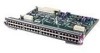
... mountable • Support for the FDDI module if one FDDI network processor module in any desired combination. Network processor modules can support two FDDI network processor modules. Figure 1-1 Cisco 4000 Series Chassis-Front Panel 1 DATA OK 2 DATA OK 3 DATA OK OK POWER SERIES H3590 Series Specifications Design specifications for the Cisco 4000 series follow: • Modular router...
... mountable • Support for the FDDI module if one FDDI network processor module in any desired combination. Network processor modules can support two FDDI network processor modules. Figure 1-1 Cisco 4000 Series Chassis-Front Panel 1 DATA OK 2 DATA OK 3 DATA OK OK POWER SERIES H3590 Series Specifications Design specifications for the Cisco 4000 series follow: • Modular router...

Hardware Maintenance Manual
Page 21
... the chassis and network processor modules) Power Wire Gauge for the Cisco 4000 series routers. RAM-Random access memory. 4. AWG-American Wire Gauge 2. Table 1-2 Cisco 4000 Series Processor and Memory Specifications Description Processor Main Memory (DRAM)2 Cisco 4000-M Cisco 4500-M Cisco 4700 40-MHz Motorola 68EC030 ... RS-449 before their acceptance as standards by the Electronic Industries Association (EIA) and Telecommunications Industry Association (TIA). Cisco 4000 Series Overview 1-3 EIA-530 DTE Console Port EIA/TIA-232 DB-25 female connector Auxiliary Port EIA/TIA-...
... the chassis and network processor modules) Power Wire Gauge for the Cisco 4000 series routers. RAM-Random access memory. 4. AWG-American Wire Gauge 2. Table 1-2 Cisco 4000 Series Processor and Memory Specifications Description Processor Main Memory (DRAM)2 Cisco 4000-M Cisco 4500-M Cisco 4700 40-MHz Motorola 68EC030 ... RS-449 before their acceptance as standards by the Electronic Industries Association (EIA) and Telecommunications Industry Association (TIA). Cisco 4000 Series Overview 1-3 EIA-530 DTE Console Port EIA/TIA-232 DB-25 female connector Auxiliary Port EIA/TIA-...

Hardware Maintenance Manual
Page 24
...• Keep the chassis area clear and dust-free during and after installation. • Always turn off the power and unplug the power cord. • Disconnect all power supplies off switch in the room in which you can weld the metal object to your eyes. • Do not perform any... conditions that might be hazardous to the terminals. Use caution; Turn off . • Before working . then take appropriate action. 2-2 Cisco ...
...• Keep the chassis area clear and dust-free during and after installation. • Always turn off the power and unplug the power cord. • Disconnect all power supplies off switch in the room in which you can weld the metal object to your eyes. • Do not perform any... conditions that might be hazardous to the terminals. Use caution; Turn off . • Before working . then take appropriate action. 2-2 Cisco ...

Hardware Maintenance Manual
Page 25
... and the layout of your equipment rack or wiring room are currently experiencing shutdowns or unusually high errors with any equipment that is disconnected from a power source, but still connected to telephone wiring or other network cabling. • Never install telephone wiring during a lightning storm. • Never install telephone jacks in...
... and the layout of your equipment rack or wiring room are currently experiencing shutdowns or unusually high errors with any equipment that is disconnected from a power source, but still connected to telephone wiring or other network cabling. • Never install telephone wiring during a lightning storm. • Never install telephone jacks in...

Hardware Maintenance Manual
Page 26
...power surges. Turn off other equipment in the rack (and in the rack, which also helps to acceptable operating temperatures without adequate circulation. General Site Requirements Site Configuration Precautions The following tips will help you avoid environmentally caused equipment failures: • Remember that the chassis cover and network processor module... test a maximum of the router power supply: • Autoranging power supply (200W, 85 to 264 VAC or 40 to 72 VDC, 50 to 60 Hz) • 6-foot electrical power cord 2-4 Cisco 4000 Series Hardware Installation and Maintenance ...
...power surges. Turn off other equipment in the rack (and in the rack, which also helps to acceptable operating temperatures without adequate circulation. General Site Requirements Site Configuration Precautions The following tips will help you avoid environmentally caused equipment failures: • Remember that the chassis cover and network processor module... test a maximum of the router power supply: • Autoranging power supply (200W, 85 to 264 VAC or 40 to 72 VDC, 50 to 60 Hz) • 6-foot electrical power cord 2-4 Cisco 4000 Series Hardware Installation and Maintenance ...

Hardware Maintenance Manual
Page 27
... operation verified Verified by Router name Router serial number Notes: Date Preparing for each system Background information placed in Site Log Environmental specifications verified Site power voltages verified Installation site prepower check completed Required tools available Additional equipment available Router received Printed documentation or UniverCD received (if ordered) Product registration (in...
... operation verified Verified by Router name Router serial number Notes: Date Preparing for each system Background information placed in Site Log Environmental specifications verified Site power voltages verified Installation site prepower check completed Required tools available Additional equipment available Router received Printed documentation or UniverCD received (if ordered) Product registration (in...

Hardware Maintenance Manual
Page 29
... ports port release screw Slot 1 Ethernet port Slot 2 Dual serial module H1033a Token Ring module Ethernet module Auxiliary port Console port Power On/off switch Slot Numbering The chassis contains slots for the modules in Figure 2-2 are as listed in which the system scans the...Preparing to Make Connections When viewed from the rear, the power cable and power switch appear on how to remove and replace network processor modules, see the sections "Removing Network Processor Modules" and "Replacing Network Processor Modules" in the chapter "Maintaining and Upgrading the Router." For ...
... ports port release screw Slot 1 Ethernet port Slot 2 Dual serial module H1033a Token Ring module Ethernet module Auxiliary port Console port Power On/off switch Slot Numbering The chassis contains slots for the modules in Figure 2-2 are as listed in which the system scans the...Preparing to Make Connections When viewed from the rear, the power cable and power switch appear on how to remove and replace network processor modules, see the sections "Removing Network Processor Modules" and "Replacing Network Processor Modules" in the chapter "Maintaining and Upgrading the Router." For ...

Hardware Maintenance Manual
Page 30
... screw Serial 1 Slot 1 AUX CONSOLE Serial 4 Serial 2 Auxiliary port Serial 0 Console port The unit numbering of these modules would be as listed in Table 2-3. H1402 a 2-8 Cisco 4000 Series Hardware Installation and Maintenance INPUT 100-240VAC 50/60HZ 3.0-1.5 AMPS Power On/off switch Table 2-3 Slot No. 1 2 3 Unit Numbering Addresses for Dual Serial and Two Ethernet...
... screw Serial 1 Slot 1 AUX CONSOLE Serial 4 Serial 2 Auxiliary port Serial 0 Console port The unit numbering of these modules would be as listed in Table 2-3. H1402 a 2-8 Cisco 4000 Series Hardware Installation and Maintenance INPUT 100-240VAC 50/60HZ 3.0-1.5 AMPS Power On/off switch Table 2-3 Slot No. 1 2 3 Unit Numbering Addresses for Dual Serial and Two Ethernet...

Hardware Maintenance Manual
Page 47
...single-mode fiber-optic cable, supporting connections at distances up to 1.2 miles (1.9 kilometers) FDDI Cable Connections The XMTR and RCVR ports of optical power. If the DAS option is included, the PHY-B port is located on top of the other. The single-mode transmitter and the multimode ...LASER RADIATION IS EMITTED FROM THESE APERTURES. 1300 NM CLASS 1 LASER PRODUCT LASERKLASSE 1 CISCO SYSTEMS, INC. 170 WEST TASMAN DRIVE SAN JOSE, CA 95134-1706 DATE: "Complies with one card fitting on the module's top card. If the distance between two connected stations is the SAS and contains ...
...single-mode fiber-optic cable, supporting connections at distances up to 1.2 miles (1.9 kilometers) FDDI Cable Connections The XMTR and RCVR ports of optical power. If the DAS option is included, the PHY-B port is located on top of the other. The single-mode transmitter and the multimode ...LASER RADIATION IS EMITTED FROM THESE APERTURES. 1300 NM CLASS 1 LASER PRODUCT LASERKLASSE 1 CISCO SYSTEMS, INC. 170 WEST TASMAN DRIVE SAN JOSE, CA 95134-1706 DATE: "Complies with one card fitting on the module's top card. If the distance between two connected stations is the SAS and contains ...

Hardware Maintenance Manual
Page 50
... lost . In addition, the system software can enable the optical bypass switch if a problem is a passive optical device powered by the FDDI module. An optical bypass switch is detected or if the operator chooses to take the router out of the ring. 2-28 Cisco 4000 Series Hardware Installation and Maintenance Network Connection Considerations Figure 2-29...
... lost . In addition, the system software can enable the optical bypass switch if a problem is a passive optical device powered by the FDDI module. An optical bypass switch is detected or if the operator chooses to take the router out of the ring. 2-28 Cisco 4000 Series Hardware Installation and Maintenance Network Connection Considerations Figure 2-29...

Hardware Maintenance Manual
Page 51
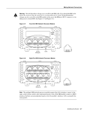
... 4 3 2 1 0 RJ-45 BRI ports LEDs 87654321 Warning Network hazardous voltages are also accessible on the BRI module in the area of the BRI port (RJ-45 connector), even when power is turned OFF. (See Figure 2-30 and Figure 2-31.) Preparing for Installation 2-29 Network hazardous voltages are accessible in... North America, where the NT1 is an RJ-45 8-pin connector. Use an appropriate cable to connect the BRI module directly to avoid...
... 4 3 2 1 0 RJ-45 BRI ports LEDs 87654321 Warning Network hazardous voltages are also accessible on the BRI module in the area of the BRI port (RJ-45 connector), even when power is turned OFF. (See Figure 2-30 and Figure 2-31.) Preparing for Installation 2-29 Network hazardous voltages are accessible in... North America, where the NT1 is an RJ-45 8-pin connector. Use an appropriate cable to connect the BRI module directly to avoid...

Hardware Maintenance Manual
Page 58
...appearance. The front panels are prepared to ensure that you received all of the following items: • Router • 6-foot (1.8-meter) power cord • Bag of all items for shipping damage. Inspecting the System Before unpacking the system, make certain that you are similar in ... container. When you unpack each shipping container, check the packing list to install it. Inspecting the System Note The ATM processor module for the Cisco 4000 series router uses identical duplex SC connectors for desktop mounting • Optional equipment (which might be emitted from CDRH FDDI....
...appearance. The front panels are prepared to ensure that you received all of the following items: • Router • 6-foot (1.8-meter) power cord • Bag of all items for shipping damage. Inspecting the System Before unpacking the system, make certain that you are similar in ... container. When you unpack each shipping container, check the packing list to install it. Inspecting the System Note The ATM processor module for the Cisco 4000 series router uses identical duplex SC connectors for desktop mounting • Optional equipment (which might be emitted from CDRH FDDI....

Hardware Maintenance Manual
Page 59
...Mount and Wall-Mount Procedures Overview • Making Console Port Connections • Making Network Connections • Connecting Routers with a DC-Input Power Supply • Making Final Connections to accommodate cables with optional rubber "feet." If your system. CHAPTER 3 Installing the Router This chapter ...describes the tasks you must attach the power cord. Sections of instructions for initial startup and configuration, you must connect an EIA/TIA-232 cable between the chassis and...
...Mount and Wall-Mount Procedures Overview • Making Console Port Connections • Making Network Connections • Connecting Routers with a DC-Input Power Supply • Making Final Connections to accommodate cables with optional rubber "feet." If your system. CHAPTER 3 Installing the Router This chapter ...describes the tasks you must attach the power cord. Sections of instructions for initial startup and configuration, you must connect an EIA/TIA-232 cable between the chassis and...

Hardware Maintenance Manual
Page 60
... the EXEC command terminal [no] padding, which sets character padding on specifying padding, refer to the appropriate Cisco IOS publication. If more than one network processor module of a given interface type is used in a system, the lowest unit number of the Token Ring cable... that your media attachment unit (MAU). Step 3 Attach your system referring to the Router." 3-2 Cisco 4000 Series Hardware Installation and Maintenance Note Flow control is the module closest to the power supply. (See the sections "Slot Numbering" and "Unit Numbering" in the chapter "Preparing for output...
... the EXEC command terminal [no] padding, which sets character padding on specifying padding, refer to the appropriate Cisco IOS publication. If more than one network processor module of a given interface type is used in a system, the lowest unit number of the Token Ring cable... that your media attachment unit (MAU). Step 3 Attach your system referring to the Router." 3-2 Cisco 4000 Series Hardware Installation and Maintenance Note Flow control is the module closest to the power supply. (See the sections "Slot Numbering" and "Unit Numbering" in the chapter "Preparing for output...

Hardware Maintenance Manual
Page 64
... generated from the router is turned OFF. (See Figure 3-7 and Figure 3-8.) The BRI network processor module supports point-to the Integrated Services Digital Network (ISDN) through an ISDN channel service unit/digital service unit...router operation, both ends of the BRI port (RJ-45 connector) even when power is disconnected, the line connection will "flap." The common carrier will provide the... NT1 connection, except in North America, where the NT1 is customer owned. 3-6 Cisco 4000 Series Hardware Installation and Maintenance kHz = kilohertz. 2. nF = nanoFarad. If this ...
... generated from the router is turned OFF. (See Figure 3-7 and Figure 3-8.) The BRI network processor module supports point-to the Integrated Services Digital Network (ISDN) through an ISDN channel service unit/digital service unit...router operation, both ends of the BRI port (RJ-45 connector) even when power is disconnected, the line connection will "flap." The common carrier will provide the... NT1 connection, except in North America, where the NT1 is customer owned. 3-6 Cisco 4000 Series Hardware Installation and Maintenance kHz = kilohertz. 2. nF = nanoFarad. If this ...
Hardware Maintenance Manual
Page 65
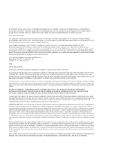
... electric shock. Network hazardous voltages are accessible in the area of the BRI port (RJ-45 connector), even when power is turned OFF. (See Figure 3-7 and Figure 3-8.) Figure 3-7 Four-Port BRI Network Processor Module PORT-7 PORT-6 PORT-5 PORT-4 ISDN BRI PORT-3 PORT-2 PORT-1 PORT-0 7 6 5 4 3 2 1 0 RJ-45 BRI ports LEDs Figure 3-8 Eight-Port...
... electric shock. Network hazardous voltages are accessible in the area of the BRI port (RJ-45 connector), even when power is turned OFF. (See Figure 3-7 and Figure 3-8.) Figure 3-7 Four-Port BRI Network Processor Module PORT-7 PORT-6 PORT-5 PORT-4 ISDN BRI PORT-3 PORT-2 PORT-1 PORT-0 7 6 5 4 3 2 1 0 RJ-45 BRI ports LEDs Figure 3-8 Eight-Port...
